Abstract
The shape of the carapace protecting the body of boxfishes has been attributed an important hydrodynamic role in drag reduction and in providing automatic, flow-direction realignment and is therefore used in bioinspired design of cars. However, tight swimming-course stabilization is paradoxical given the frequent, high-performance manoeuvring that boxfishes display in their spatially complex, coral reef territories. Here, by performing flow-tank measurements of hydrodynamic drag and yaw moments together with computational fluid dynamics simulations, we reverse several assumptions about the hydrodynamic role of the boxfish carapace. Firstly, despite serving as a model system in aerodynamic design, drag-reduction performance was relatively low compared with more generalized fish morphologies. Secondly, the current theory of course stabilization owing to flow over the boxfish carapace was rejected, as destabilizing moments were found consistently. This solves the boxfish swimming paradox: destabilizing moments enhance manoeuvrability, which is in accordance with the ecological demands for efficient turning and tilting.
Keywords: boxfish, hydrodynamics, manoeuvrability, course stability, swimming, drag force
1. Introduction
Boxfishes (Ostraciidae: Tetrodontiformes) are one of the few groups of vertebrates that evolved a bony encasing of the body. This carapace consists of a large number of sutured, hexagonal plates of dermal bone [1,2] and forms a rigid armour providing protection against bites of coral-reef-dwelling predators [3]. Because the rigid carapace restricts movement, body axis undulation to power swimming is limited to rare, single beats of the caudal peduncle and fin to accelerate the boxfish up to their top speeds (approx. 5 body lengths s−1) in a burst-and-coast mode of swimming [4]. However, boxfish generally move slowly within the confined space of their territory, where they feed on planktonic and small benthic organisms [5]. To power slow rectilinear swimming and turning manoeuvres, they rely on the movement of their pectoral, dorsal and anal fins [4,6].
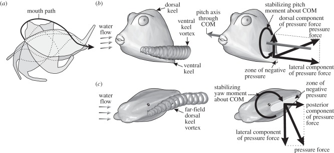
Boxfish are impressively manoeuvrable for fish with a rigid body [6] and can perform lateral turning manoeuvres of 180° during forward locomotion with a near-zero turning radius [7] (figure 1a). The tight relationship between the angle by which the caudal fin bends to the side and the turning radius suggests that boxfish have accurate control over turning by engaging the caudal fin as a rudder [6,7]. This high turning performance is in line with the demands of their life in spatially complex habitats where they perform a lot of manoeuvring.
Figure 1.
Illustration of the boxfish swimming paradox. (a) The capacity of boxfish to perform 180° turns with near-zero turning radii is illustrated (adapted from [7]) showing body outlines at 0.32 s intervals for Ostracion meleagris. (b,c) The automatic course-stabilization hypothesis [8–11] is illustrated for Rhinesomus triqueter. During nose-up pitch angles of attack (b), a vortex is formed resulting in a zone of negative pressure just above the left and right ventral keels (shown in oblique latero-frontal view). The dorsal component of the pressure force at this zone of the carapace causes a moment that will reorient the boxfish in line with the flow (i.e. a stabilizing, nose-down pitch moment about the centre of mass (COM)). During yaw angles of attack (c), a vortex is formed resulting in a zone of negative pressure on the far-field side of the dorsal keel (shown in dorsal view). The lateral component of the pressure force at this zone causes a stabilizing moment about the centre of mass forcing the head to turn right.
In addition to its role in anti-predator defence, the boxfish carapace is also thought to possess important hydrodynamic properties. Working with replicas of boxfish carapaces from several species attached to force transducers in a flow tank, Bartol et al. [8–11] demonstrated two important properties. Drag coefficients (i.e. drag force normalized to frontal surface area and the square of flow speed with respect to the object) of the carapace can be very low—below 0.13 for some species [10] which is quite impressive for a relatively bluff and box-like body [12]. This low body drag of boxfish has inspired robotics engineers [13] as well as one of the world's largest car manufacturers [14]. Secondly, flow around the carapace is thought to help boxfish to maintain straight swimming trajectories by course-stabilizing moments that are exerted by the water on the boxfish's body as soon as the incoming flow direction is no longer parallel to the anterior-to-posterior body axis [8–11] (figure 1b,c). For example, if the boxfish tilts nose-up, vortices will develop above the ventrolateral ridges of the carapace (the so-called ventral keels; figure 1b). As the upward suction effect of these vortices on the body is stronger posterior of the centre of mass, this will cause a nose-down pitching moment (figure 1b). Over time, this will bring the boxfish back in line with the flow. A similar mechanism is at work for the boxfish under a yaw angle of attack: stronger vorticity on to the far-field side of the boxfish would help in realignment with the flow direction [8–11] (figure 1c). This automatic course stabilization is hypothesized to be important to damp perturbations when swimming and to keep boxfish on their desired paths when swimming in turbulent waters [9,10].
However, the lifestyle-related demands for high manoeuvrability are in conflict with the permanent course-stabilizing effect of the flow around the carapace of boxfish: course stabilization by definition means that any change in course is countered by the stabilizing mechanism. Evolution appears to have produced a carapace shape that is hydrodynamically stable but manoeuvring is energetically costly. It is not immediately obvious how this automatic stabilizing hydrodynamic effect of the carapace can be reconciled with the observed agile swimming behaviour of boxfish [6,7], giving rise to what we term the boxfish swimming paradox.
The paradoxical and controversial nature of the course-stabilization hypothesis calls for re-evaluation and extended analyses. In this study, the three-dimensional balance of forces on the boxfish body under pitch and yaw angles of attack, the resulting pitch and yaw moments, and the effect of the position of the centre of mass will be determined by computational fluid dynamics (CFD). This approach will be assisted by experimental moment and drag force measurements in a real flow tank, including an assessment of the effect of swimming velocity on yaw moments. Together, this will allow us to gain significant insight into course-stability mechanics of boxfish, which in turn will help us to better understand the hydrodynamic mechanisms behind the boxfish swimming paradox.
2. Material and methods
2.1. Model species and three-dimensional laser scans
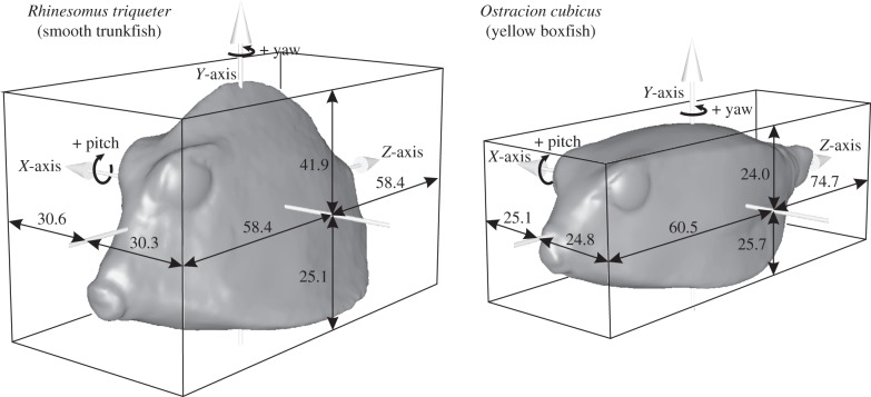
Boxfish (Ostraciidae) show a large variation in carapace shape. The shape of a middle cross-section roughly varies from being triangular (e.g. Lactophrys and Rhinesomus species) to square (e.g. Ostracion species) [10]. The following representatives from both morphotypes were chosen as model species for our analysis: the smooth trunkfish Rhinesomus triqueter (Linnaeus 1758), which has a clear triangular shape, and the yellow boxfish Ostracion cubicus (Linnaeus 1758), which, as its name suggests, has a cubic carapace. For these two species, three-dimensional surface laser scans (NextEngine 3D scanner HD, NextEngine, Santa Monica, CA, USA) were made from preserved specimens from the Los Angeles County Museum of Natural History (accession number LACM 8088 for R. triqueter and LACM 42481 for O. cubicus). Each specimen was scanned twice: one 360° set of scans to capture the body and tail, and one bracket set of scans to capture the head. After fusing these scans, cleaning of the models was performed in ScanStudio software (NextEngine) and subsequently Geomagic (Geomagic, Research Triangle Park, NC, USA), which was used to remove the fins and restore the eyes. The three-dimensional laser scans were then aligned with a reference frame (X = left–right axis, Y = ventrodorsal axis, Z = anterior–posterior axis) and placed with their centre of volume at the coordinate system's origin. Both models have a volume of 0.15 dm3. Frontal surface areas were 22.7 cm2 (R. triqueter) and 21.7 cm2 (O. cubicus). The linear dimensions relative to the centre of volume are illustrated in figure 2. This computed position of the centre of volume for O. cubicus (at 49% of snout tip to start of peduncle; at 48% the ventral to dorsal axis) closely approximated the position of the centre of mass measured empirically for O. meleagris (at 46 and 45%, respectively) [4].
Figure 2.
Geometry of the models used in this study. Three-dimensional surfaces of the two model species with indication of size (in mm) with respect to the position of the centre of volume, which corresponds to the origin of the reference frame.
2.2. Computational fluid dynamics
A first approach to study the hydrodynamic performance of the carapace of the two ostraciid model was to perform CFD simulations. The oriented, watertight stereo-lithography files from the laser scans were then imported into Ansys TGrid 5.0.6. (Ansys Inc., Canonsburg, PA, USA) to be incorporated in a flow domain, rotated to the desired angle of attack and to be meshed (figure 3).
Figure 3.

Flow domain, mesh, boundary conditions and coordinate system used for computational fluid dynamics. The box-shaped flow domain with indication of the boundary conditions for each surface, and the position of the boxfish carapace is shown on the left. Only the midsagittal section of the mesh is shown. A mesh refinement zone (white box) surrounds the boxfish to increase the accuracy in resolving the frontal pressure wave and wake patterns. An enlarged view on the eye region of the boxfish mesh is shown on the right. Scale bar left, 0.5 m; right, 0.02 m.
A box-shaped flow domain with a width and height of 0.84 m (greater than 20 boxfish heights and greater than 27 boxfish widths; boxfish centred) and a length of 1.98 m (greater than 14 boxfish lengths; boxfish closest to the velocity inlet face at 20% along this length) was constructed in TGrid (figure 3). To serve as a refinement of the region demanding the most accuracy, a 0.4 m long refinement zone in which the tetrahedra grew relatively slowly (growth factor of 1.1) towards the outer layers, surrounds the boxfish. The surface of the boxfish was meshed with 0.32 mm sized triangles (figure 3), while the outer boundary was much coarser (20 mm triangle edges). This resulted in a finite-volume mesh consisting of about 10 million cells. A mesh convergence study was performed for R. triqueter, showing that further refinement to a mesh of 20 million cells (boxfish triangle size 0.2 mm) only resulted in a difference of about 1% for drag and lift force. This means that the previous mesh was fine enough, and the best choice given the doubling of computational time of this final refinement.
The square boundary face in front of the boxfish was defined as a velocity inlet with a flow speed of 0.5 m s−1 (approximately 3.5 body lengths s−1). This velocity was chosen in analogy with previous workers [9], who estimated a similar speed to be representative of fast swimming in relatively large individuals. The boxfish carapace surface was defined as a ‘wall’ where the no-slip boundary condition applies. The remaining five rectangular faces of the outer boundary were set as pressure outlets with a zero gauge pressure (figure 3), since they are assumed too distant from the object to encounter pressure disturbances in the flow.
The meshes were imported in the CFD solver Ansys Fluent 14.0 on a workstation equipped with two six-core processors and 24 GB of rapid access memory. The fluid in our model was assigned a water density of 998.2 kg m−3 and a dynamic viscosity of 1.001 Pa s. At a Reynolds number (Re) based on body length of about 50 000, the wake of the fish will be turbulent, but the boundary layer is probably laminar. To account for the effects of turbulence at such relatively low Reynolds numbers, the Menter Shear Stress Transport (Transition SST) model was used [15]. This model is more accurate and reliable for a wider class of flows then other Reynolds-averaged Navier–Stokes turbulence closure schemes (calculating the mean flow without first calculating the full time-dependent flow field), by combining different turbulence models for the inner region of the boundary layer and for the outer, free shear flow region. A validation test showed that this model (along with our other CFD settings and mesh characteristics) calculates a drag coefficient of a sphere of 0.48 (Re = 50 000), which closely matches experimentally measured values of about 0.47 at this Re [16]. In our simulations, the incoming flow is assumed to contain zero turbulent energy. Iterative convergence was reached safely after 2500 iterations, taking about 12 h of calculation on our set-up.
2.3. Flow-tank measurements
The force and moment measurements were done in a 300 l flow tank. The dimensions of the rectangular test section with laminar flow were 25 × 25 cm in cross section and 50 cm in length. During experiments, a Perspex plate covered the top of the test section in order to prevent wave formation. Two separated honeycomb-shaped meshes upstream of the test section served as flow straighteners to ensure a laminar water flow entering the test section (verified by flow visualization). Physical models were produced at 1 : 1 scale from the same scan surfaces that were used for the CFD study (figure 2) using a three-dimensional printing/prototyping technique (Contex Designmate CX, Contex A/S, Alleroed, Denmark). The models were made water resistant by impregnation with epoxy resin. Each model was coated using a primer (Motip EAN 8711347040544) and a black paint (Motip EAN 8711347040018). A hole was then drilled in the ventral side of the model and a threaded insert mounted in it, such that the heart-line of the insert was in line with the model's centre of mass.
For the measurements, the model was mounted on a 5 mm diameter stainless steel rod which was attached to the measuring platform above the tank, so that the model was exactly in the middle of the cross-section of the tank. The platform was hanging from a frame on top of the flow tank, to which it was attached from the corners by four thin flat metal (spring steel) strips that allowed motion only in the direction of the flow. On one side, the platform was connected to a force sensor (Vernier Dual range 10N/50N, DFS-BTA, Vernier Software and Technology, Beaverton, OR, USA) which was connected to a computer using a Vernier LabPro Interface. Data were recorded using Vernier LoggerPro v. 3.8 software. The accuracy of the force platform system was confirmed by drag coefficients of two spheres (60 and 40 mm diameter) measured to be 0.47 ± 0.02 at the appropriate Re, which exactly matched the literature value of 0.47 [16].
The resistance output had to be corrected for the presence of the rod holding it. The rod without the model was, however, much more prone to vibration than when being attached to the model. We therefore corrected for the drag of the rod by mounting the rod with attached model and measuring the drag at the same range of speeds as the model measurements, but now with the model at different heights (close to the centre of the measuring section). This allowed us to quantify the drag per unit rod length and correcting for total rod length (9.5 cm).
For measuring yaw moments, the rod with the model was mounted to a fixed platform. The rod was mounted in a custom-made ball bearing seat that served as an axle that could rotate freely and was virtually frictionless. After setting the angle of the model relative to the flow. The moment could be measured as a function of flow speed using a 4 cm arm that was fixed to the axle, using the same force sensor as described before. In analogy with the sign definition for yaw moment directions in the CFD study (figure 2; only positive angles of attack simulated), a moment acting to increase the angle between flow and the heart-line of the model was identified as positive.
3. Results
3.1. Drag force
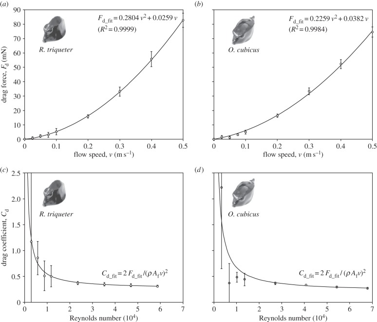
Forces on the three-dimensional-printed boxfish models positioned in-line with the flow in the flow tank varied as a function of flow speed (figure 4). For both species, a tight correlation between drag force Fd and the square of flow speed (v2) was observed (R2 > 0.99; figure 4a,b), which is in agreement with the classic Rayleigh drag equation of Fd = 0.5 Cd Af ρ v2, where Cd is the shape-dependent drag coefficient, Af the frontal surface area and ρ the water density (1000 kg m−3). The drag coefficient of both species decreased with increasing Reynolds number (Re = ρ v L μ−1, with L the length of the fish along the flow direction, and μ the dynamic viscosity of water at 20°C of 1.002 × 10⁻³ Pa s). The minimum Cd for R. triqueter in our range of flow velocities was 0.308 ± 0.018 (mean ± s.d.; v = 0.5 m s−1, Re = 58 880; figure 4c). For the same flow speed, CFD calculated a Cd of 0.27 (for this species, FZ = 76 mN). The minimum Cd for O. cubicus was 0.270 ± 0.013 measured in the flow tank (v = 0.5 m s−1, Re = 67 860; figure 4d) and 0.26 (FZ = 70 mN) obtained by CFD. CFD also suggested that forces are the dominant source of hydrodynamic resistance in the swimming direction, as they were calculated to be about four times (for R. triqueter) or five times (for O. cubicus) higher than viscous shear forces.
Figure 4.
Results for drag from the flow-tank experiments. (a,b) Drag forces and (c,d) drag coefficients are displayed. Second-order polynomial fits (Fd_fit) and the derived functions for drag coefficients (Cd_fit) illustrate the relationship with flow speed (a,b) or Reynolds number (c,d). Error bars denote the between-sampling standard deviation.
3.2. Yaw moments
The yaw moments about the centre of volume as a function of yaw angle of attack showed a similar pattern for both CFD and the moments measured in the flow tank. When the yaw angle of attack is increased from its original orientation in-line with the flow (0° yaw angle of attack), the yaw moment about the centre of volume of the carapace becomes increasingly positive (i.e. rotational direction away from the flow or destabilizing) to reach a peak for R. triqueter at either 30° (flow tank at 0.4 and 0.5 m s−1) or 40° (flow tank up to 0.3 m s−1, CFD at 0.5 m s−1; figure 5a), and for O. cubicus at either 40° (flow tank from 0.3 to 0.5 m s−1) or 50° (flow tank up to 0.2 m s−1; CFD at 0.5 m s−1; figure 5b). For larger yaw angles of attack, the yaw moments decrease but remain destabilizing (figure 5). For the yaw moment to become negative (i.e. course stabilizing) at a yaw angle of attack of 20°, the hypothetical yaw axis should lie in the orbital region or slightly anterior thereof, as indicated by the line of zero yaw moment that crosses the orbits of the eyes for both species (figures 6b and 7b).
Figure 5.

Yaw moments about the centre of volume as a function of yaw angle of attack for (a) R. triqueter and (b) O. cubicus. Experimental data are given for five different flow speeds. CFD data for 0.5 m s−1 are shown by the full circles and dashed line. Error bars shown for the experimental 0.5 m s−1 data denote the between-sampling standard deviation.
Figure 6.
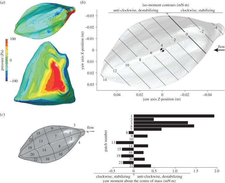
CFD results for R. triqueter at a 20° yaw angle. The graphs show pressure on the boxfish carapace surface (a; top = dorsal view, bottom = frontal view), iso-moment contours as a function of yaw axis position (b) and moment on separate patches of the carapace surface (c). The position of the centre of mass (assuming homogeneous material density inside the carapace) is indicated on the iso-moment contour graph. Note that the neutral position of the yaw axis (zero moment; bold line) lies considerably anterior of the centre of mass (b), so that a destabilizing moment occurs for rotation about a yaw axis through the centre of mass.
Figure 7.
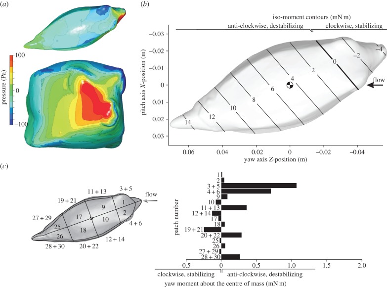
CFD results for O. cubicus at a 20° yaw angle. The graphs show pressure on the boxfish carapace surface (a; top = dorsal view, bottom = frontal view), iso-moment contours as a function of yaw axis position (b) and yaw moment on separate patches of the carapace surface (c). The position of the centre of mass (assuming homogeneous material density inside the carapace) is indicated on the iso-moment contour graph. Similar to R. triqueter (figure 6), the neutral position of the yaw axis (zero moment; bold line) lies considerably anterior of the centre of mass (b), so that a destabilizing moment occurs for rotation about a yaw axis through the centre of mass.
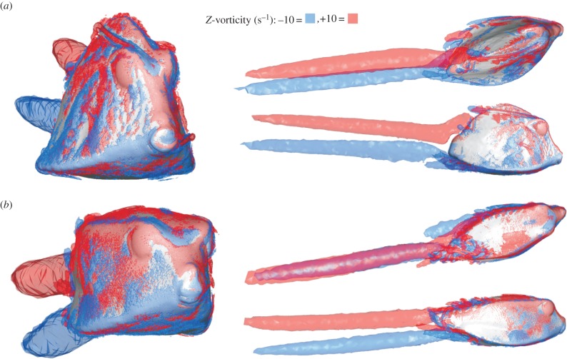
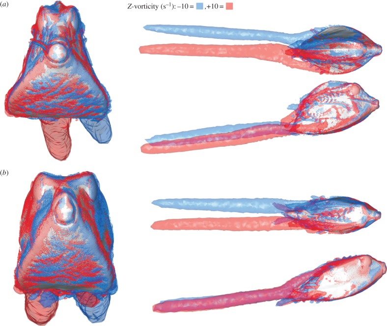
The pattern of pressure exerted at the carapace surface at 20° yaw angle (head turned to the left) is characterized by a strong frontal pressure wave (positive values) from the mouth to the eye region at the right side of the head of both species (red to yellow colouring in figures 6a and 7a). Narrower strips of relatively large negative pressure can be found from the left (i.e. far-field) side of the mouth towards the left side of the dorsal keel, below the right (i.e. near-field) ventral keel, on top of the right dorsal keel of O. cubicus, and on the right medio-lateral region of R. triqueter (blue to dark-green colouring in figures 6a and 7a). Two large vortices are present in the wake of the boxfish at 20° yaw: a clockwise (facing flow direction) dorsal vortex originating from the left side of the boxfish, and an anti-clockwise ventral vortex originating and fusing from both sides (figure 8).
Figure 8.
Vorticity patterns calculated by CFD for 20° yaw angles of attack in (a) R. triqueter and (b) O. cubicus. Each displayed simulation includes frontal (left), dorsal (top right), and lateral (bottom right) views on the boxfish carapace with +10 Hz (clockwise facing the flow direction; red) and −10 Hz (anti-clockwise facing the flow direction; blue) iso-vorticity surfaces.
Yaw moments calculated on separate patches of the carapace surface from the CFD simulations show a dominant effect of the frontal pressure on yaw moment (figures 6c and 7c). A strongly destabilizing moment is found owing to flow effects on the head surfaces of R. triqueter (patches 1–4 in figure 6c; 5.18 mN m) and O. cubicus (patches 1–6 in figure 7c; 1.84 mN m). Stabilizing moments are exerted by the flow on the lateral far-field side body surfaces posterior of the centre of mass of R. triqueter (patches 13, 15, 19 and 21 in figure 6c; −1.27 mN m) as well as O. cubicus (patches 19 and 21 in figure 7c; −0.251 mN m), but these are completely cancelled by opposing (i.e. destabilizing) moments on the corresponding surfaces on the opposite (i.e. near-field) side of the body (1.29 mN m for R. triqueter; and 0.293 mN m for O. cubicus; figures 6c and 7c).
3.3. Pitch moments
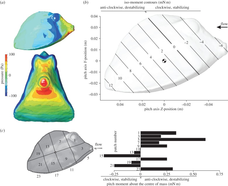
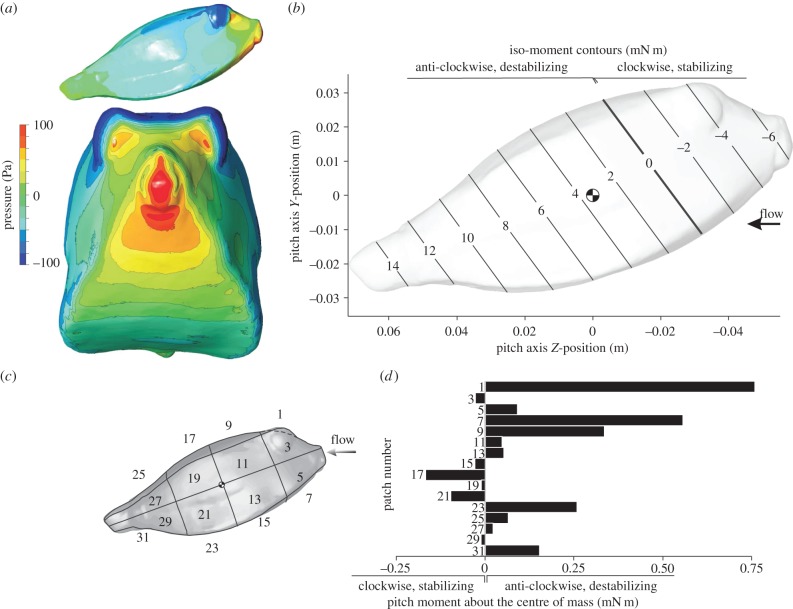
The pitch moment about the centre of volume of the carapace calculated by CFD for a flow speed of 0.5 m s−1 was positive for nose-up angles of attack, and negative for nose-down angles of attack for both species. This means that for both nose-up and nose-down orientation the rotational direction of the hydrodynamic moment on the boxfish carapace causes rotation away from the flow direction, or, in other words, acts to destabilize carapace orientation in flow. In our 20° interval sample, the largest positive moments (0.0040 N m for R. triqueter, 0.0056 N m for O. cubicus) were calculated for a pitch angle of attack of 40°. The largest negative moments (−0.0028 N m for R. triqueter, −0.0053 N m for O. cubicus) were calculated for a pitch angle of attack of −40°. For the pitch moment to become negative (i.e. rotational direction towards the flow or stabilizing) at a pitch angle of attack of 20°, the hypothetical pitching axis should lie at 34% of the carapace length from the tip of the mouth (instead of 48% for the centre of volume) for R. triqueter (figure 9b) and at 30% (compared with 45% for the centre of volume) for O. cubicus (figure 10b). As increasing the roughness of the boxfish surface (from 0 to 2 mm) or increasing turbulence intensity of the incoming flow (from 5 to 50%) both further increased the calculated destabilizing moments by a few percentages, these parameters have no influence on the conclusions of our study.
Figure 9.
CFD results for R. triqueter at a 20° pitch angle. The graphs show pressure on the boxfish carapace surface (a; top = lateral view, bottom = frontal view), iso-moment contours as a function of pitch axis position (b) and pitch moment on separate patches of the carapace surface (c). The position of the centre of mass (assuming homogeneous material density inside the carapace) is indicated on the iso-moment contour graph. Note that the neutral position of the pitch axis (zero moment; bold line) lies considerably anterior of the centre of mass (b), so that a destabilizing moment occurs for rotation about a pitch axis through the centre of mass.
Figure 10.
CFD results for O. cubicus at a 20° pitch angle. The graphs show pressure on the boxfish carapace surface (a; top = lateral view, bottom = frontal view), iso-moment contours as a function of pitch axis position (b) and pitch moment on separate patches of the carapace surface (c). The position of the centre of mass (assuming homogeneous material density inside the carapace) is indicated on the iso-moment contour graph. Note that, similar to R. triqueter (figure 9), the neutral position of the pitch axis (zero moment; bold line) lies considerably anterior of the centre of mass (b), so that a destabilizing moment occurs for rotation about a pitch axis through the centre of mass.
The pattern of pressure at 20° pitch angle shows a frontal zone of positive pressure, which peaks at the mouth and the region just ventral of the mouth (red to yellow in figures 9a and 10a). Most of the latero-dorsal region experiences a negative pressure (blue to dark-green colouring in figures 9a and 10a), with strips of peak negative pressure at the eyes (continuing towards the ventral keels in R. triqueter; figure 9a) and on top of the ventral keels. A left–right symmetrical pair of wake vortices can be observed in both species. Each of these vortices forms as a fusion of a vortex originating just above the ventral keels, and one that forms at the dorsal region (figure 11).
Figure 11.
Vorticity patterns calculated by CFD for 20° pitch angles of attack in (a) R. triqueter and (b) O. cubicus. Each displayed simulation includes frontal (left), dorsal (top right) and lateral (bottom right) views on the boxfish carapace with +10 Hz (clockwise facing the flow direction; red) and −10 Hz (anti-clockwise facing the flow direction; blue) iso-vorticity surfaces.
Pitch moments calculated on separate patches of the carapace surface from the CFD simulations show a dominant effect of the frontal pressure on pitch moment (figures 9c and 10c). A strongly destabilizing moment is found owing to flow effects on the head surfaces of R. triqueter (patches 1, 3 and 5 in figure 9c; 1.15 mN m) and O. cubicus (patches 1, 3, 5 and 7 in figure 10c; 1.38 mN m). Stabilizing moments are exerted by the flow on the lateral body surfaces posterior of the centre of mass of R. triqueter (patches 13, 15, 19 and 21 in figure 9c; −0.744 mN m) as well as O. cubicus (patches 17, 19 and 21 in figure 10c; −0.283 mN m). However, these stabilizing moments are opposed by destabilizing moments on the ventral surfaces posterior of the centre of mass, which cancel the stabilizing effect for 76% in R. triqueter (0.563 mN m on patches 17 and 23 of figure 9c) and completely in O. cubicus (0.411 mN m on patches 17, 19 and 21 in figure 10c).
4. Discussion and conclusion
As stability and manoeuvrability have competing requirements, this trade-off will be reflected in the morphological adaptations for locomotion in different ecological niches [17]. In other words, body designs that are adapted for stable movement are not suitable for high manoeuvrability and vice versa [18]. As boxfish manoeuvre skilfully about the reef [4,6,7], we can expect to find a suite of morphological traits that enhance manoeuvring performance. Paradoxically, however, the flow around the carapace of boxfish was previously shown to cause automatic (and thus permanent) course stabilization, with a special role in this process for the keels that are found in most ostraciid species [8–11] (figure 1). The shape of the carapace was thus hypothesized to be adapted to stabilize rectilinear swimming in boxfishes.
However, our results showed that the opposite is true: hydrodynamic moments are destabilizing for both boxfish species with a triangular cross section R. triqueter (figures 5a and 6b) and boxfish species with a square cross section O. cubicus (figures 5b and 7b). This pattern of course instability owing to the flow of water over the carapace was shown by both CFD and flow-tank measurements for yaw angles of attack. The moments of opposite sign previously reported as evidence for course stabilization by the carapace of boxfish [9,10] could thus not be reproduced. Our flow-tank measurements showed that destabilizing yaw moments are consistent over a range of swimming speeds from slow (0.1 m s−1 or approx. 0.7 body length s−1) to fast (0.5 m s−1 or approx. 3.5 body length s−1; figure 5). Using CFD, we found similar course-destabilizing moments for pitching (figure 9b and 10b) and showed that the yaw and pitch instability cannot be attributed to an inaccurate estimate of the centre of mass (figures 6b, 7b, 9b and 10b). Our results resolve the apparent boxfish swimming paradox by revealing that there is no yaw and pitch stabilization system imparted by the carapace. Instead, our results suggest that boxfishes have a capacity for yaw and pitch manoeuvrability that may match their ability for turning [7].
The static equilibrium of hydrodynamic forces on the boxfish's body to cause yaw and pitch moments about the centre of mass is dominated by the frontal pressure wave on the head. During yaw angles of attack, positive pressure on the near-field side of the head with a centre just in front and below of the eye (figures 6a and 7a) has a resultant force vector (pushing perpendicular onto the surface) with a large moment arm for yaw rotation about an axis through the centre of mass. In addition, patches of negative pressure on the far-field side of the head cause a net destabilizing yaw moment. As shown in previous studies [8–11], the posterior, negative pressure above the ventral keel of the far-field side causes stabilization (as shown in figure 1c). Yet, its size and intensity as well as moment arm are much smaller than the above destabilizing pressures. Furthermore, we showed that the limited amount of yaw stabilization generated by the flow on the far-field lateral side is completely cancelled by destabilizing flow effects on the opposite (i.e. near-field) side of the carapace (figures 6c and 7c). For pitch angles of attack, the frontal pressure forces ventral of the mouth (figures 9a and 10a) dominate the total destabilizing pitch moment (figures 9c and 10c). Also here we could confirm the previously predicted stabilizing effect on the lateral carapace walls at the posterior end of the fish (figure 1b), but again these were countered by opposing, destabilizing pitch moments on the ventral surfaces just below that zone (figures 9c and 10c). Consequently, although stabilizing hydrodynamic effects on specific locations on the body surface, as hypothesized in previous studies [8–11] (figure 1b,c), could be confirmed (figures 6c, 7c, 9c and 10c), their overall impact on the pitch or yaw moment balance is negligible.
Fins could potentially play an important role in mitigating instability and one limitation of our study is that we have focused exclusively on carapace hydrodynamics. For example, the caudal fin is known to play a central role in controlling turning manoeuvres in a wide range of fish species [19] including boxfish [7]. In order to estimate the impact of the caudal fin on the overall yaw moment by flow over the body and tail, we will estimate the effect of adding a straight caudal fin in our two boxfish model species at 20° angle of attack. If we assume that the caudal fin has a surface area of 0.001 m2 (conservative estimate based on lateral-view pictures size-scale to our model), a moment arm to the centre of mass of 0.09 m (distance of the centre of the caudal fin surface to the centre of mass multiplied by the cosine of 20°) and behaves as a thin plate with a lift coefficient of 0.5 (value reported for rectangular plates of similar aspect ratio at Re = 300 [20] and also approximated for higher aspect ratio flat plates at higher Re [21]), the resulting yaw moment would be −5.6 mN m. As the caudal fin's stabilizing yaw moment is almost equal in magnitude to the destabilizing moment on the carapace without tail (i.e. 6.9 and 6.5 mN m measured for R. triqueter and O. cubicus, respectively; figure 5), the straight caudal fin adds a considerable amount of yaw stability to the inherently destabilizing flow effect on the rest of the body. Although these calculations clearly suggest a very important role for the caudal fin in controlling yaw in boxfishes, a more detailed study is needed to unravel how the caudal fin is precisely engaged in this control.
We hypothesize that control of yaw and pitch in Ostraciidae, and probably also in other rigid bodied tetraodontiform fishes such as smooth pufferfishes (Tetraodontidae) and spiny puffers (Diodontidae), is performed by elements that can be engaged as active controllers (fin curvature, displacement and area) instead of structures that are restricted to passive, unconscious control (fixed anatomical characteristics such as the shape of the carapace) to prevent a decrease in manoeuvring performance. For example, previous studies showed how the caudal fin functions as a rudder for steering [4,6,7]. Tetraodontiform fishes use coordinated, synchronized, often out-of-phase movements of their five fins to produce a wide repertoire of controlled swimming movements [4,22–24]. With these muscle-activated, hydrodynamic controllers at hand, it probably became superfluous to add a passive stability controller, such as the proposed self-correcting vortex action on the carapace [8–11], which cannot be turned off when manoeuvring. Yet, the cubic- or prism-shaped carapaces with their radially extending keels or other protrusions in Ostraciidae may also have a stabilizing role by increasing the resistance to rolling.
The drag-reduction performance of the two boxfish species studied was relatively low compared with more generalized body shapes of fish: the measured minimal drag coefficients (0.31 for R. triqueter and 0.27 for O. cubicus) are considerably higher than quantified previously for more typical, fusiform fish. Cichlid (Oreochromis niloticus) bodies under the same CFD simulation settings result in a drag coefficient of about 0.15 at a Reynolds number of 75 000 (S. Van Wassenbergh 2014, unpublished data). A medium-sized adult trout Oncorhynchus nerka without pectoral fins at a Re of 5 × 10⁵ had a similar drag coefficient of 0.155 [25]. Although boxfish clearly outperform true boxes or spheres at a similar Re (Cd of 1.05 and 0.47 [16]), the demands of size and rigidity for anti-predator defence come at a considerable cost of increased drag force during swimming or station holding. On the other hand, as the way of life of boxfish mainly involves confined-space manoeuvring and hardly includes migratory swimming, this relatively high drag may result in only a limited overall energetic penalty, causing the selective pressure towards streamlining to be low.
In conclusion, our results showed that the overall static force balance on the carapace of the flow at yaw and pitch angles of attack is destabilizing rather than course stabilizing. This effect was consistent for a wide range of natural flow speeds (0.1–0.5 m s−1) and centre of mass positions for both a species with a triangular cross-sectional shape (R. triqueter) and one with a rectangular cross section (O. cubicus). The stabilizing moments by the vortices posterior of the centre of mass were negligible compared with the moment caused by the frontal pressure wave on the head. This destabilizing flow over the boxfish's body promotes manoeuvrability, which matches well with the prevailing swimming style of boxfish.
Acknowledgements
We thank Malenthe Teunis for her help in this study.
Funding statement
This research was funded by a grant from the University of Antwerp (BOF/KP 24346) to S.V.W. and NSF grant DEB 0842397 to M.E.A.
References
- 1.Randall JE. 1972. The Hawaiian trunkfishes of the genus Ostracion. Copeia 1972, 756–768. ( 10.2307/1442733) [DOI] [Google Scholar]
- 2.Besseau L, Bouligand Y. 1998. The twisted collagen network of the box-fish scutes. Tissue Cell 30, 251–260. ( 10.1016/S0040-8166(98)80073-6) [DOI] [PubMed] [Google Scholar]
- 3.Vermeij GJ. 1987. Evolution and escalation: an ecological history of life. Princeton, NJ: Princeton University Press. [Google Scholar]
- 4.Hove JR, O'Bryan LM, Gordon MS, Webb PW, Weihs D. 2001. Boxfishes (Teleostei: Ostraciidae) as a model system for fishes swimming with many fins: kinematics. J. Exp. Biol. 204, 1459–1471. [DOI] [PubMed] [Google Scholar]
- 5.Myers RF. 1999. Micronesian reef fishes: a comprehensive guide to the coral reef fishes of Micronesia. Barrigada, Guam: Coral Graphics. [Google Scholar]
- 6.Blake RW. 1977. On ostraciiform locomotion. J. Mar. Biol. Assoc. UK 57, 1047–1055. ( 10.1017/S0025315400026114) [DOI] [Google Scholar]
- 7.Walker JA. 2000. Does a rigid body limit maveuverability? J. Exp. Biol. 203, 3391–3396. [DOI] [PubMed] [Google Scholar]
- 8.Bartol IK, Gordon MS, Gharib M, Hove JR, Webb PW, Weihs D. 2002. Flow patterns around the carapaces of rigid-bodied, multi-propulsor boxfishes (Teleostei: Ostraciidae). Integr. Comp. Biol. 42, 971–980. ( 10.1093/icb/42.5.971) [DOI] [PubMed] [Google Scholar]
- 9.Bartol IK, Gharib M, Weihs D, Webb PW, Hove JR, Gordon MS. 2003. Hydrodynamic stability of swimming in ostraciid fishes: role of the carapace in the smooth trunkfish Lactophrys triqueter (Teleostei: Ostraciidae). J. Exp. Biol. 206, 725–744. ( 10.1242/jeb.00137) [DOI] [PubMed] [Google Scholar]
- 10.Bartol IK, Gharib M, Webb PW, Weihs D, Gordon MS. 2005. Body-induced vortical flows: a common mechanism for self-corrective trimming control in boxfishes. J. Exp. Biol. 208, 327–344. ( 10.1242/jeb.01356) [DOI] [PubMed] [Google Scholar]
- 11.Bartol IK, Gordon MS, Webb PW, Weihs D, Gharib M. 2008. Evidence of self-correcting spiral flows in swimming boxfishes. Bioinspir. Biomim. 3, 014001 ( 10.1088/1748-3182/3/1/014001) [DOI] [PubMed] [Google Scholar]
- 12.Summers A. 2005. Boxed up to go. Nat. Hist. 114, 38–39. [Google Scholar]
- 13.Kodati P, Hinkle J, Winn A, Deng X. 2008. Microautonomous robotic ostraciiform (MARCO): hydrodynamics, design, and fabrication. IEEE Trans. Robot. 24, 105–117. ( 10.1109/TRO.2008.915446) [DOI] [Google Scholar]
- 14.Sharfman B. 2006. Mercedes and the boxfish. Scientist 20, 17–18. [Google Scholar]
- 15.Menter FR. 1994. Two-equation eddy-viscosity turbulence models for engineering applications. AIAA J. 32, 1598–1605. ( 10.2514/3.12149) [DOI] [Google Scholar]
- 16.Hoerner SF. 1965. Fluid-dynamic drag. Bricktown, NJ: Hoerner Fluid Dynamics. [Google Scholar]
- 17.Weihs D. 2002. Stability versus maneuverability in aquatic locomotion. Integr. Comp. Biol. 42, 127–134. ( 10.1093/icb/42.1.127) [DOI] [PubMed] [Google Scholar]
- 18.Fish FE. 2002. Balancing requirements for stability and maneuverability in cetaceans. Integr. Comp. Biol. 42, 85–93. ( 10.1093/icb/42.1.85) [DOI] [PubMed] [Google Scholar]
- 19.Domenici P, Blake RB. 1997. The kinematics and performance of fish fast-start swimming. J. Exp. Biol. 200, 1165–1178. [DOI] [PubMed] [Google Scholar]
- 20.Taira K, Colonius T. 2009. Three-dimensional flows around low-aspect-ratio flat-plate wings at low Reynolds numbers. J. Fluid Mech. 623, 187–207. ( 10.1017/S0022112008005314) [DOI] [Google Scholar]
- 21.Anderson JD., Jr 2001. Fundamentals of aerodynamics. New York, NY: McGraw-Hill. [Google Scholar]
- 22.Arreola VI, Westneat MW. 1996. Mechanics of propulsion by multiple fins: kinematics of aquatic locomotion in the burrfish (Chilomycterus schoepfi). Proc. R. Soc. Lond. B 263, 1689–1696. ( 10.1098/rspb.1996.0247) [DOI] [Google Scholar]
- 23.Gordon MS, Hove JR, Webb PW, Weihs D. 2000. Boxfishes as unusually well-controlled autonomous underwater vehicles. Physiol. Biochem. Zool. 73, 663–671. ( 10.1086/318098) [DOI] [PubMed] [Google Scholar]
- 24.Wiktorowicz AM, Lauritzen DV, Gordon MS. 2010. Powered control mechanisms contributing to dynamically stable swimming in porcupine puffers (Teleostei: Diodon holocanthus). In Animal locomotion (eds Taylor GK, Triantafyllou MS, Tropea C.), pp. 87–97. Berlin, Germany: Springer. [Google Scholar]
- 25.Webb PW. 1975. Hydrodynamics and energetics of fish propulsion. Bull. Fish. Res. Board Can. 190, 1–158. [Google Scholar]


