Abstract
More than 1.2 million people worldwide require regular hemodialysis therapy to treat end stage renal failure. Current hemodialysis systems are too expensive to support at-home hemodialysis where more frequent and longer duration treatment can lead to better patient outcomes. The key cost driver for hemodialysers is the cost of the hemodialysis membrane. Microchannel hemodialysers are smaller providing the potential to use significantly less membrane. Prior work has demonstrated the use of sealing bosses to form compression seals in microchannel hemodialysers. In this paper, estimates show that the percentage of the membrane utilized for mass transfer is highly dependent on the design and registration accuracy of adjacent blood and dialysate laminae. Efforts here focus on the development of a self-registration method to align polycarbonate laminae compatible with compression sealing schemes for membrane separation applications. Self-nesting registration methods were demonstrated with average registration accuracies of 11.4 ± 7.2 μm measured over a 50 mm scale. Analysis shows that the registration accuracy is constrained by tolerances in the embossing process. A dialysis test article was produced using the self-nesting registration method showing a measured average one-dimensional misregistration of 18.5 μm allowing a potential 41.4% of the membrane to be utilized for mass transfer when considering both microchannel and header regions. Mass transfer results provide evidence of a twofold to threefold increase in membrane utilization over other designs in the existing literature.
Keywords: Microchannel, Hemodialysis, Self-Registration, Compression Sealing, Membrane
1 Introduction
Patients undergoing hemodialysis give up large portions of their lives for treatment. The typical regimen consists of three 4 to 5 hour filtration sessions per week [1]. During these sessions, the patient’s blood completes a circuit through the body and the dialysis machine once every 20 minutes at a flow rate of 250 mL/min [2]. Such a high blood flow rate is unnatural and causes severe stress and nausea in patients. During time periods between treatments, waste products build up naturally in the blood [3]. When toxins reach high levels they begin to diffuse into the body which is one major factor in shortening life. Cardiovascular damage from these toxins is responsible for substantial morbidity and mortality [4]. Other side effects can include bone damage, muscle cramps, and abnormal heart rhythms. More than 1.2 million people worldwide require regular hemodialysis therapy, and of those, 300,000 are patients in the U.S. alone [5, 6].
The most common type of hemodialyser is the hollow fiber configuration in which blood flows through an array of hollow filtration tubes (fibers) within a flow field of dialysate which is used to carry diffused toxins away [7]. Hollow fiber hemodialysers are very efficient due to their counter-flow arrangement with up to 10,000 fibers ranging down to as small as 200 μm in diameter. One problem with hollow fiber hemodialysers is that the distance between fibers is not fixed due to the flaccid nature of the fibers within the dialysate flow field. So while the mass transfer within the fiber is excellent, the mass transfer outside of the fiber can vary requiring more membrane surface area and, consequently, larger devices.
Recent studies have shown that more frequent, longer-duration hemodialysis significantly reduces negative effects on the body [8]. Microchannel-based hemodialysers provide a means for longer-duration dialysis by allowing for cheaper, more compact dialysis equipment that can be operated at home. The smaller size is attributed to the higher mass transfer rates on the dialysate side of the hemodialsyser associated with the shorter diffusional distances in microchannels [9]. Microchannel hemodialysers require less membrane material than hollow fiber hemodialysers providing an opportunity to significantly reduce costs. Also, smaller hemodialysers can reduce the overall size of the hemodialysis system, thus decreasing system capital requirements and making at-home hemodialysis more affordable.
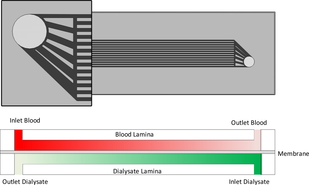
Microchannel hemodialysers (MCHDs) have been constructed by entrapping hemodialysis membranes between flat polymeric laminae with 100 μm scale channels on both sides of the membrane. Figure 1 (top) shows the top view of a counter-flow MCHD test article designed by Warner Tuhy et al. [10] to measure mass transfer of urea across the membrane. The device had 13 machined channels on each side of the membrane. On the left end of the device in Figure 1 (bottom), spent dialysate is exiting the device from the dialysate lamina while untreated blood is entering the device on the blood lamina. On the right end of the device, fresh dialysate enters while the purified blood exits. A membrane is entrapped between the two laminae which seals the device while allowing mass transfer to occur without the mixing of the two fluids.
Figure 1.
(top) Top view of MCHD test article developed by Warner-Tuhy et al. [10]; (top left) Closeup view of headers and channels; (bottom) Cross section of the test article showing the counter-flow nature of the blood and dialysate laminae.
1.1 The Importance of Registration
In this paper, the registration between two laminae is determined through the use of fiducials that establish local coordinate systems at the same location on each lamina. When assembling the laminae, therefore, misregistration is determined by measuring the misalignment between the two corresponding fiducials in two dimensions [11]. Additional details for measuring misregistration are provided in the experimental section.
To understand the effect of misregistration on the device economics, consideration is given to the amount of membrane area, A, required in a typical device based on:
| (1) |
where Ṁi [mg/min] is the average mass transfer rate of the ith species, k [cm/min] is the average mass transfer coefficient, C1 [mg/dL] is the blood urea concentration at the start of the treatment and C2 [mg/dL] is the urea concentration in the dialysate exiting the device. Urea mass transfer is the standard for characterizing hemodialyser performance [12]. High blood urea levels, such as those for hemodialysis patients, can be above 50 mg/dL [13]. Assuming that the human body contains approximately five liters of blood, an end stage renal disease patient may have around 2500 mg of urea within their blood stream at the point of treatment [13]. A typical nocturnal home dialysis treatment would extend over 6 hours (360 minutes) requiring an average mass transfer rate of 6.94 mg/min. For the MCHD developed by Warner-Tuhy et al. [10] using 200 micrometer wide channels by 100 micrometers deep, overall urea mass transfer coefficients were in the range of 0.07 to 0.14 cm/min and the average simulation result was 0.08 cm/min. Using values of 0.08 cm/min for k, 50 mg/dL for C1 and 25 mg/dL for C2, a membrane area of approximately 347 cm2 would be required for microchannel hemodialysis.
Currently the membrane costs $0.018 per cm2 based on the price of a single roll (which reduces with volume pricing). Based on this membrane cost, the membrane cost per device would be over $6. However, this assumes that all of the membrane is used for mass transfer. Due to the need for channel headers, membrane supports between channels, and sealing area around the periphery of the device, not all of the membrane can be utilized for mass transfer. The percentage of the membrane that is utilized for mass transfer is termed “membrane utilization”.
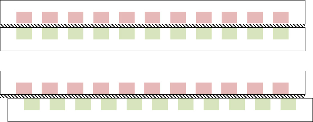
In the Warner Tuhy et al. [10] configuration above, 200 μm wide ribs were used to support the 25 μm thick hemodialysis membrane placed over the channel array (Figure 2 top). In these support regions, it is assumed that all mass transfer is blocked. Further, if ribs are not closely aligned they will either partially or completely block adjacent channels leading to even worse membrane utilization as shown in Figure 2 (bottom). Specifically, if the 200 μm configuration discussed above was assembled with a 100 μm misregistration, a 50% reduction in membrane utilization would occur within the channel array.
Figure 2.
Effect of misregistration on membrane utilization in a counter-flow design. (top) Perfect alignment between microchannels. (bottom) A misregistration of 50% leads to 50% less membrane available for mass transfer between channels.
Warner-Tuhy [9] and Anderson [14] investigated the use of cross-flow MCHDs in order to avoid aligning channels on top of one another. While cross-flow arrays are invulnerable to registration errors, membrane utilization worsens because all ribs on one side cross all channels on the opposite side. For example, the estimated membrane utilization for the Warner Tuhy et al. [10] configuration above is 14% compared with 12.5% for the Warner-Tuhy [9] and Anderson [14] cross-flow devices. In either case, the membrane cost per device increases to $44.61 and $49.97, respectively; well above the current price of hemodialysers.
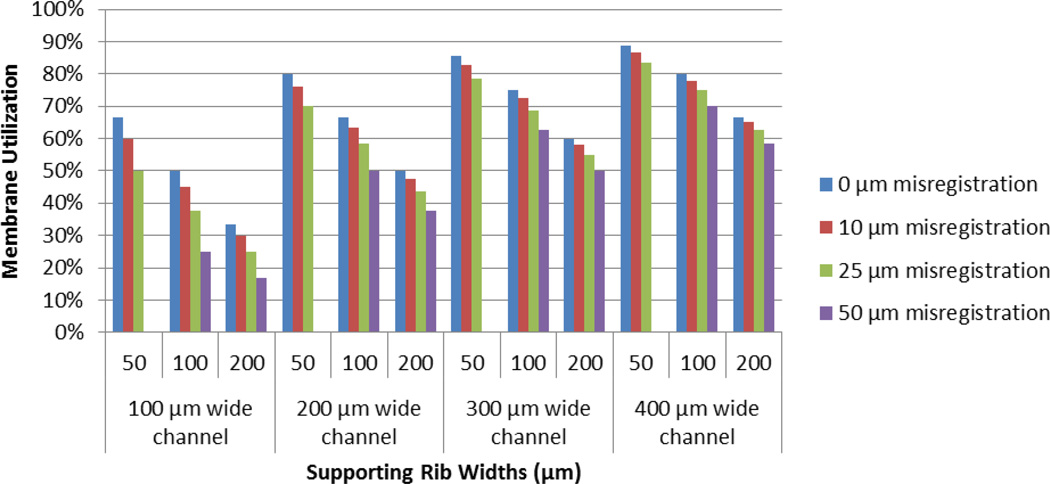
For the purposes of analysis, a counter-flow design was used due to the higher log-mean concentration differences provided by counter-flow designs, compared with parallel-flow and cross-flow designs, which offers the opportunity to use less membrane due to higher average mass transfer rates [15]. The effect of both channel array design and misregistration on membrane utilization in counter-flow MCHDs is presented in Figure 3. The model assumes that misregistration is occurring as shown in Figure 2 (bottom) and does not consider the effects of misregistration orthogonal to the cross-section. One implication of Figure 3 is that the wider the channels and narrower the ribs, the higher the membrane utilization. However, narrow ribs must be aligned more precisely to support membrane on the other side of the device. Membrane utilization is not given for several configurations having 50 μm wide ribs with 50 μm misregistration since the membrane becomes unsupported. Theoretically, for microchannel arrays with 50 μm wide ribs and 200 μm or wider channels, 25 μm misregistrations provide membrane utilizations at or above 70%.
Figure 3.
Sensitivity analysis of the effect of misregistration on membrane utilization within microchannel hemodialysers having varied channel and rib sizes.
1.2 Objective
The objective of this work was to develop a self-registration method to align polycarbonate laminae in a manner compatible with compression sealing schemes for microchannel hemodialysers. Efforts are made to evaluate the effectiveness of this method by investigating the level of layer-to-layer registration that can be accomplished using this method and the consequent effects of the registration accuracy of this self-registration method on the mass transfer of hemodialysis membranes. The efficacy of the method is further evaluated by comparing the estimated membrane utilization of devices designed and made using this method with the estimated membrane utilization of device designs within the literature.
2 Materials and Methods
In this work, hot embossing methods are used to pattern the channels and headers on each of the polycarbonate laminae. In prior work, Warner-Tuhy [9], Warner-Tuhy et al. [10], and Anderson [14] used the exterior regions of patterned laminae to form a hermetic compression seal with the hemodialysis membrane acting as a gasket. This work builds on the work of Paul and Ward [16] who demonstrated the use of ~10 μm high sealing bosses [17] in concert with a Gambro AN69ST hemodialysis membrane to hermetically seal microchannel laminae.
Prior to compression sealing, laminae must be registered to one another. In prior work, MCHD devices have used pin registration to align laminae to each other. One disadvantage of pin registration is the size of the registration features needed for registering the thin polymer laminae. Pins must be rigid and, therefore, have larger diameters making it difficult to enable sub-25 μm registration. Further, pin registration requires through holes which can become leakage paths. Finally, pin registration is difficult to implement within high speed roll-to-roll manufacturing which is needed to support production.
Very little work exists in the technical literature regarding the self-registration of micro-scale features. Paul and Thomas [11] and Wattanutchariya and Paul [18] investigated the self-registration of metal microchannel laminae taking advantage of the thermal expansion mismatch between the fixture and laminae during diffusion bonding cycles. Registration accuracies below 10 μm were found over 50 mm length scales. In this work, nested alignment features are used to restrict all 6 degrees of translational and rotational freedom between laminae.
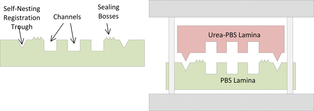
Figure 4 (left) shows a caricature of the lamina cross-section to be implemented in this work. One-hundred-micrometer-scale channels are embossed at the same time as sealing bosses and self-nesting registration features (adjacent ridges and troughs). A 25 μm thick hemodialysis membrane is inserted between the laminae to provide mass transfer and also to provide gasketing in concert with the sealing bosses. Sealing bosses compress the membrane forming compression seals around all channel and header features. Self-nesting registration ridges compress the membrane into the adjoinining troughs to nest with one another, improving the accuracy of registration while not constraining the compression depth of the sealing bosses. Therefore, self-nesting features must be significantly larger than the thickness of the membrane.
Figure 4.
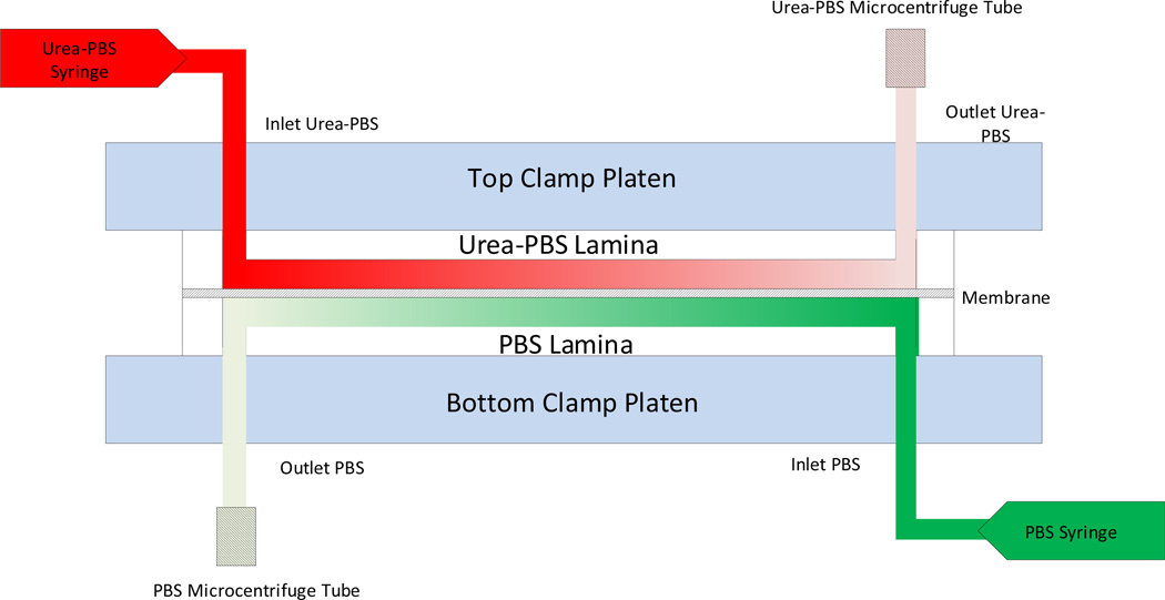
(left) Conceptual cross-section of a microchannel lamina with all three depth levels; (right) diagram of alignment within the clamp (PBS means phosphate buffer saline).
This design requires the ability to produce lamina features at multiple depths. Laser (355 nm) machining was used to create hot embossing masters. Channel, header and registration troughs are laser machined into polyethylenimine (PEI) masters and transferred via hot embossing (Jenoptic HEX01) into polysulfone (PSO) submasters. Then sealing bosses and registration ridges are laser machined into the PSO submaster which is used to hot emboss channels, headers, sealing bosses and self-nesting registration features into polycarbonate (PC) substrates [17]. To minimize dimensional inaccuracies during the embossing step, a new master was developed for each set of laminae to eliminate changes in the dimensions of the master over time due to thermal effects. Afterwards, inlet and outlet through holes are cut into PC laminae using laser machining. Finally, the laminae are stacked, registered and clamped for evaluation (Figure 4 right). The PEI master was embossed into the PSO at a temperature of 195 °C for 240 seconds at a pressure of 3.8 kPa. The PEI and PSO masters were embossed into the PC at a temperature of 175 °C for 240 seconds at a pressure of 3.8 kPa.
2.1 Misregistration Analysis
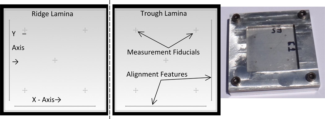
Figure 5 shows the two laminae each containing two perpendicular alignment features that nest with the corresponding lamina. These self-nesting registration features were placed near the edges of the laminae to be as far apart as possible. Together the two ridges restrict three degrees of freedom (two translational and one rotational). Placement of the two laminae on top of one another eliminates three additional degrees of freedom. After registration, the two laminae were clamped together with a self-registration ridge and trough facing each other using a clamp. The clamp (Figure 5 right) provided optical access to the middle of the laminae to interrogate misregistration by measuring the relative distance between fiducials on both laminae using an optical microscope at 200X. No channels, headers, sealing bosses or membranes were required for this analysis.
Figure 5.
Laminae with ridge (left) and trough (middle) alignment features marked with corresponding measurement fiducial positions. Laminae are assembled along a fold line between the laminae. (right) Clamp used for registering laminae.
As mentioned, the laminae designs included fiducials for measuring the alignment between the two laminae [11]. Since the laminae in this research are transparent, fiducials can face one another keeping the measurement in one single plane which is important for optical microscopy. Optical microscopy measurements were made in two directions with the use of fiducials. Misregistration measurements were performed on an optical microscope (Leica DMLM x200) zoomed to 200X using a video overlay (Boeckder VIA-100). The crosshairs of the video overlay were put in the middle of the laser machined lines to account for variability in line widths. A total of five laminae sets were measured. Each lamina set had a total of 20 measurements taken. Each of the five crosshair locations were measured twice in both the X and Y directions.
2.2 Mass Transfer Tests
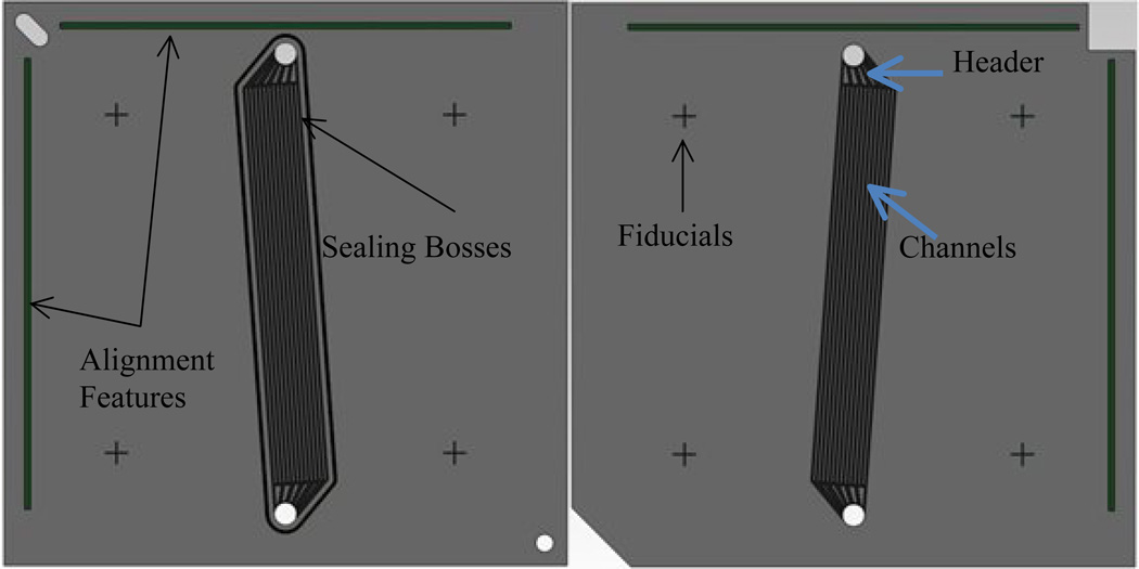
To verify the effectiveness of the self-registration methods, mass transfer results of the test articles were compared with expected results based on mass transfer coefficients derived from Warner-Tuhy et al. [10] Laminae designs for the test articles are shown in Figure 6. The channel arrays and headers mimic those of Warner-Tuhy et al. [10] with 13 channels having the same channel depth (100 μm) and channel width (200 μm) and an estimated rib width of 200 μm. Although these designs are similar, they differ from Warner-Tuhy et al. [10] in four ways. First, self-nesting registration features are used to register the laminae to one another; ridges on the bottom and troughs on the top laminae. While the bottom lamina utilizes pin registration holes to align the bottom lamina to the inlet and outlet holes of the clamp, no pin registration features exist on the top lamina. This is to ensure that the clamp pins do not influence the registration of the top lamina to the bottom lamina. Second, sealing bosses are used around the edge of the channel headers and microchannel array to form a compression seal. Third, in order to use sealing bosses, the headers and array have been made to mirror each other so that the length of the sealing bosses on the bottom lamina can press against a flat surface on the top lamina. Fourth, the channel lengths are much shorter at 3.5 cm compared with 5.6 cm for the shortest length from Warner-Tuhy et al. [10]
Figure 6.
Laminae designs for the dialyser test articles used for validating improvements in registration: bottom trough lamina (left); and top ridge lamina (right).
Fabrication of the dialysis test articles followed methods similar to those used to fabricate alignment test articles except that the hemodialysis membrane was extended over the registration features. Details of the clamp and assembly procedure used to hermetically seal the device can be found elsewhere [16]. Two different sets of aligned and misaligned test articles were produced. The difference in the two laminae designs was the position of one set of channels relative to the self-registration features. In the aligned case, the distance between the microchannel array and the self-registration features on both laminae was the same. In the misaligned case, this distance was off by the width of a single channel for one lamina (200 μm). Headers in both cases were aligned.
To optically assess the level of registration in each test article, the flow distribution through the device and device leakage, water with red and green dye was loaded into the blood and dialysate syringes, respectively. A syringe pump (Harvard Apparatus Twin Syringe Pump Model MA1 SS-3333) was used in this experiment with two 5 mL syringes. Syringes were connected to clamp inlets. Photographs were made using a digital single lens reflex camera (Canon EOS 7D).
2.2.1 Mass Transfer Test Loop and Protocol
For mass transfer tests, one syringe was filled with a phosphate buffer saline (PBS) while the other was filled with a urea-PBS solution. The PBS was produced by dissolving 8.77g NaCl, 0.23g KH2PO4 and 1.82g K2HPO4·3H2O in 950 mL of deionized water. After dissolving these components, the pH was adjusted with 1M NaOH or HCl, up to 1 liter. This was then divided into two 500 mL samples. The PBS sample was used to simulate the dialysate while the 500 mL sample was used to simulate blood by dissolving 500 mg of urea into it providing an initial urea concentration of 100 mg/dL.
After hooking the syringe pump to the clamp and setting the flow rate to 125 μL/min, the pump was started yielding an average velocity of 1.02 cm/sec through the channels and an average channel residence time of 3.45 seconds. The system, starting at the entrance of the plate to the end of the exit tubing, had a calculated residence time of 1.31 minutes. Consequently, flow in the dialyser was allowed to reach a steady state over a period of 3 minutes before samples were collected. Fluid samples (~0.1 mL) were collected in micro-centrifuge tubes over the course of approximately one minute. A minimum of three samples (replicates) were collected from each device setup. The sets of aligned and misaligned lamina were loaded and unloaded between each of three runs that each set underwent. These samples were analyzed with the urea assay immediately following testing. A diagram of this flow setup can be seen in Figure 7.
Figure 7.
Diagram of mass transfer setup.
2.2.2 Urea Assay
Urea concentration of samples was measured using a urea assay performed by reacting o-phthalaldehyde and primaquine bisphosphate with urea. The reaction causes a color change, the intensity of which can be measured using a spectrophotometer. Urea assay reagents in this test were prepared based on the work of Jung et al. [19] and Zawada et al. [20]. After mass transfer tests, assaying was conducted by first mixing each of the reagents directly in a microwell-plate. Dialysis samples were diluted by 20X by pipetting 95 μL of PBS and 5 μL of the sample into individual wells. One well, containing 50 μL of urea-PBS solution at 100 mg/dL was used as the standard, and one well, containing just PBS, was used as the negative control. The well-plate was then placed in an incubator at 37°C for 1 hour. Optical density (OD) of each well was then measured in triplicate using a Perkin Elmer 1420 Multilabel Counter VICTOR3V spectrophotometer at 450 nm under 0.1 seconds per reading.
After samples were collected and their absorbance had been converted into urea concentration, experimental mass transfer rates were calculated by multiplying the volumetric flow rate by the change in concentration of either the PBS or the urea-PBS side of the device. This experimental mass transfer rate was then used to calculate the mass transfer area using Equation 1 and the results of Warner-Tuhy et al. [10]
3 Results and Discussion
3.1 Registration Accuracy
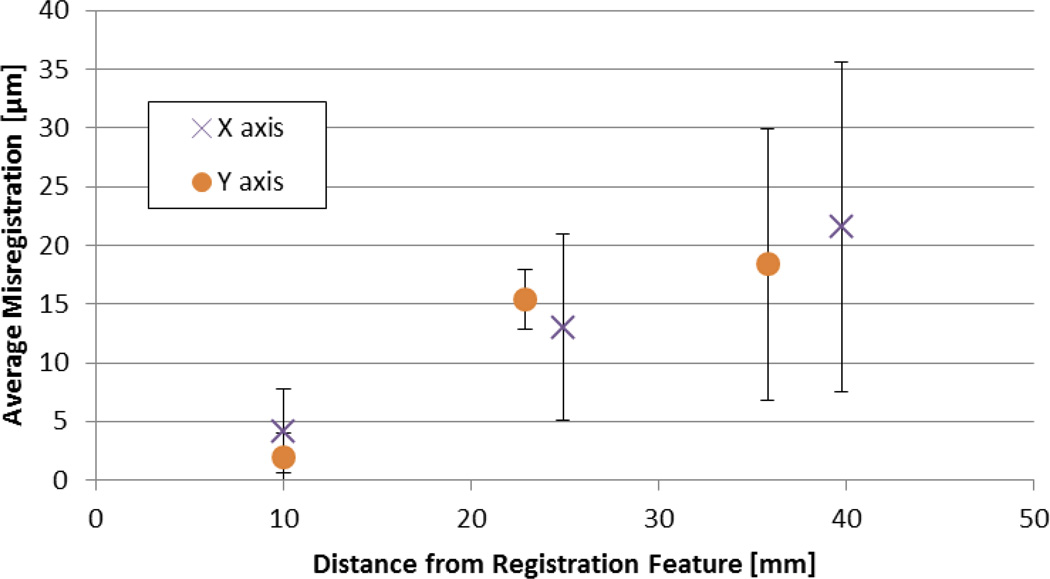
Self-nesting registration troughs were found to be 294.2 ± 21.1 μm wide and 170.9 ± 13.9 μm deep while self-nesting registration ridges were 276.7 ± 32.7 μm wide and 169.0 ± 10.1 μm high. The profile of the features were parabolic similar to those found in Kim et al. [17]. Without the use of membranes, these features were found to produce an average one-dimensional misregistration of 11.4 ± 7.2 μm. Figure 8 shows the one-dimensional misregistration in both X and Y directions as a function of distance from the registration features. Misregistration was found to increase with the distance from the registration features. Using linear regression of this data and based on linear extrapolation, the distance from the registration feature at which the X and Y axis misregistrations equaled a maximum of 25 μm (allowing for a reasonably high membrane utilization based on the economic analysis above) was 42.9 and 39.4 mm, respectively. Therefore, assuming linear extrapolation, average misregistrations of 25 μm are possible up to 80 mm. Further, assuming that the registration features could be placed in the center of the device, this suggests that this level of average misregistration could be manageable up to about 160 mm.
Figure 8.
Misregistration in the X and Y axes of the lamina. Error bars are estimate of standard deviation.
To investigate the cause of the inaccuracy, the absolute position of the fiducials on the trough and ridge laminae were measured using a coordinate measuring machine (Mitutoyo BHN305) adapted with an optical probe (Ram Optical Video Probe, ROI 30-4000-00). Results revealed that the ridge lamina was always larger than the trough lamina. It is known that variable shrinkage in the embossing step can result from variations in demolding time, embossing pressure, cooling rate, friction between the master and lamina, thermal expansion, and features on the lamina [21, 22]. The ridge lamina required one embossing cycle using one master (PEI) while the trough lamina required two cycles using a master (PEI) and a sub-master (PSO). This suggests that additional improvements in registration might be possible by compensating for the differences in feature size on the trough and ridge laminae.
3.2 Registration of the Mass Transfer Test Article
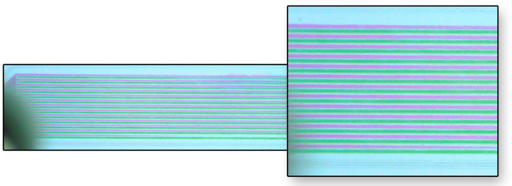
Once the mass transfer test articles were setup within the clamping fixture, visual tests were performed to check that the registration was as expected. After leakage was eliminated, water with red and green dye were pumped into the device. An aligned sample can be seen in Figure 9. The measured average one dimensional misregistration in the aligned sample was 18.5 μm.
Figure 9.
Aligned test article with red and green dyed water flowing through the device.
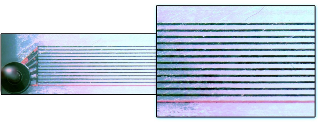
As shown in the aligned sample, some channels only had one color of fluid flowing while other channels had both fluids flowing through them (black). Single fluid channels were caused by bubbles which blocked the channels. A misaligned sample is shown in Figure 10. The measured average one dimensional misregistration in the misaligned sample was 209.4 μm compared with a “designed” misregistration of 200 μm suggesting overall misregistration of 9.4 μm. This sample shows a uniform and well defined flow. The channels all have flow, with the exception of the bottom red channel which appears to be blocked by a bubble. Removal of all bubbles was found to be difficult due to the high surface-area-to-volume ratio nature of the channel array [23].
Figure 10.
Misaligned test article with red and green dyed water flowing through the device.
3.3 Mass Transfer Tests
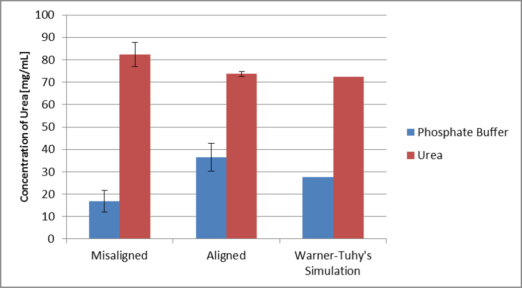
Using a spectrophotometer and samples of known urea concentration, a straight line calibration curve was generated providing an R2 value of 0.91. Using the calibration factor, the amount of mass transferred per sample was calculated. For mass transfer testing, one pair of aligned and one pair of misaligned test articles were produced and tested. Results are shown in Figure 11. As shown, the urea concentration on the phosphate buffer (dialysate) side went up on both the aligned and misaligned test setup. The urea concentration in the PBS for the aligned channel is over twice that in the misaligned channel.
Figure 11.
Interpolated urea concentrations from the standard curve.
Comparing results from the aligned device to the simulation in Warner-Tuhy et al. [10] (final urea concentration of 72.5 mg/dL), the final urea concentration of the aligned device is within 2% of expected results on the urea side which is in excellent agreement. When looking at the phosphate buffer side, there is a 9% improvement over the simulation results. This could be explained by the extra header contact area due to the use of sealing bosses. Removing the extra header contact area in this study puts the final urea concentration at 30 mg/dL which is within 5% of the Warner-Tuhy simulation. Additional error can be explained by the size of the error bar in Figure 11.
An estimate for the best membrane utilization capable in the present device is 44.9% based on the apparent mass transfer area of the membrane when perfectly aligned and the overall size of the membrane needed to assemble the test article (i.e. a membrane size just over the dimensions of the sealing bosses). Adjusting for a measured average misregistration of 18.5 μm, the estimated membrane utilization reduces to 41.4%. This compares favorably with the design of Warner-Tuhy et al. [10] which had longer channels and membrane utilization approaching 14%. One factor affecting membrane utilization in Warner-Tuhy et al. [10] was the use of a larger membrane in order to compression seal the laminae without the use of sealing bosses.
Mass transfer rates for the Warner-Tuhy et al. [10] device were calculated to be 0.065 mg/min based on experimental results. In comparison, mass transfer rates of 0.033 to 0.046 mg/min were calculated for the aligned test article produced in this study by multiplying the flow rates with the average change in urea concentration from the urea side and the PBS side, respectively. The smaller mass transfer rate in the present device is due to the shorter channel array used in the present device.
Based on these mass transfer results, a total mass transfer area, A, of 0.641 to 0.959 cm2 was calculated using Equation 1. Mass transfer coefficients used here were 0.70 and 0.75 cm/min which were the smallest mass transfer rates as experimentally determined by Warner-Tuhy et al. [10] under a flow rate of 1.0 cm/sec. These areas correspond to membrane utilizations of 26.1% to 39.0%. The membrane utilization is within 2.4% to 15.3% (5.8% to 37.0% error) of the estimated membrane utilization of 41.4% for the fabricated device given which is in good agreement. This confirms a twofold to threefold improvement in membrane utilization over Warner-Tuhy et al. [10] Calculated mass transfer results are shown below in Table 1 and Table 2.
Table 1.
Calculated mass transfer area based on device dimensions and registration accuracy.
| Registration Condition | Estimated Mass Transfer Area [cm2] |
Membrane Utilization |
|---|---|---|
| Perfect Registration | 1.103 | 44.9% |
| Measured 18.5 μm misregistration | 1.016 | 41.4% |
Table 2.
Calculated membrane utilization based on a mass transfer rate.
| Mass Transfer Coefficient, ko [cm/min] |
Mass Transfer Rate, Ṁurea [mg/min] |
Estimated Mass Transfer Area, A [cm2] |
Membrane Utilization |
|---|---|---|---|
| 0.070 | 0.046 | 0.959 | 39.0% |
| 0.070 | 0.033 | 0.687 | 28.0% |
| 0.075 | 0.046 | 0.895 | 36.4% |
| 0.075 | 0.033 | 0.641 | 26.1% |
Finally, these results show that while mass transfer is not completely halted when channels are completely misaligned, mass transfer is significantly reduced. Some of the mass transfer that did occur in the misaligned test articles could have occurred in the headers since they were exposed to the membrane. The device has an area of 110 mm2 of mass transfer area in the aligned device. The headers account for 17% of the area in the device. If mass transfer occurred at an equal rate in the header as it did in the channels, then no more than about 6.2 mg/dL (36.5%) of the final urea concentration could be accounted for because of the headers. Subtracting this amount from the total mass transferred leaves a final urea concentration of at least 10.7 mg/dL transferred in the misaligned device suggesting that the headers alone cannot account for the mass transfer within the misaligned channels. Some of the remaining mass transfer within the channel array can be explained by the fact that the supporting ribs did not have sealing bosses so were not as compressed as the compression sealed regions allowing for mass transfer through the membrane in these regions. Also, the geometry of the surfaces used to compress the membrane was not as precise as that shown in Figure 2. The edges of the channels were somewhat rounded suggesting potential mass transfer paths. Further, the concentration of urea does not add up to 100 mg/dL showing a lack of mass balance and evidence for experimental error.
4 Conclusions
In this paper, a self-registration method was developed to align polycarbonate laminae for membrane separation applications compatible with hot embossing and compression sealing schemes. Without membranes, registration measurements showed that this technique could manage acceptable registration accuracies up to an 80 mm scale and, with clever design, up to 160 mm scale. Analysis showed that the registration accuracy is constrained by tolerances in the embossing process. Based on these findings, it is expected that registration accuracies could be further improved by designing for the expected change in the dimensions of the embossed laminae. With membranes, the registration accuracy of the method was found to worsen by an additional 50%. A functioning dialysis test article was produced and found to permit a twofold to threefold increase in membrane utilization over other designs in the existing literature. Improvements in membrane utilization were found to be associated with the combination of the improved registration accuracy and the use of sealing bosses which was enabled by the use of the new self-registration method.
Acknowledgements
This work was funded by the National Institute of Health grant R01EB011567. The authors would like to thank Matt Coblyn, Steve Etringer, Thomas Lindner, Dusty Ward and Neill Thornton for their valuable help in setting up experimental studies.
Footnotes
Publisher's Disclaimer: This is a PDF file of an unedited manuscript that has been accepted for publication. As a service to our customers we are providing this early version of the manuscript. The manuscript will undergo copyediting, typesetting, and review of the resulting proof before it is published in its final citable form. Please note that during the production process errors may be discovered which could affect the content, and all legal disclaimers that apply to the journal pertain.
References
- 1.Lacson E, Brunelli SM. Hemodialysis treatment time: a fresh perspective. Clin J Am Soc Nephrol. 2011;6:2522–2530. doi: 10.2215/CJN.00970211. [DOI] [PubMed] [Google Scholar]
- 2.Azar AT. Increasing dialysate flow rate increases dialyzer urea clearance and dialysis efficiency: an in vivo study. Saudi J Kidney Dis Transpl. 2009;20:1023–1029. [PubMed] [Google Scholar]
- 3.McPhatter LL, Lockridge RS, Albert J, Anderson H, Craft V, Jennings FM, Spencer M, Swafford A, Barger T, Coffey L. Nightly home hemodialysis: improvement in nutrition and quality of life. Adv Ren Replace Ther. 1999;6:358–365. doi: 10.1016/s1073-4449(99)70048-8. [DOI] [PubMed] [Google Scholar]
- 4.Vanholder R, Laecke S, Glorieux G. What is new in uremic toxicity? Pediatric Nephrology. 2008;23:1211–1221. doi: 10.1007/s00467-008-0762-9. [DOI] [PMC free article] [PubMed] [Google Scholar]
- 5.U.S. Renal Data System. Bethesda, MD: National Institutes of Health, National Institute of Diabetes and Digestive and Kidney Diseases; 2011. [Accessed: 09-Aug-2012]. USRDS 2011 Annual Data Report: Atlas of Chronic Kidney Disease and End-Stage Renal Disease in the United States. Available: http://www.usrds.org/atlas.aspx. [Google Scholar]
- 6.Grassmann A, Gioberge S, Moeller S, Brown G. ESRD patients in 2004: global overview of patient numbers, treatment modalities and associated trends. Nephrology Dialysis Transplantation. 2005;20:2587–2593. doi: 10.1093/ndt/gfi159. [DOI] [PubMed] [Google Scholar]
- 7.Cussler EL. Diffusion mass transfer in fluid systems. New York: Cambridge University Press; 2009. [Google Scholar]
- 8.Lindsay RM, Alhejaili F, Nesrallah G, Leitch R, Clement L, Heidenheim AP, Kortas C. Calcium and phosphate balance with quotidian hemodialysis. American Journal of Kidney Diseases. 2003;42:24–29. doi: 10.1016/s0272-6386(03)00534-1. [DOI] [PubMed] [Google Scholar]
- 9.Warner-Tuhy A. MS Thesis. Corvallis, OR: Oregon State University; 2009. Mass Transfer of Urea, Creatinine and Vitamine B-12 in a Microchannel based Membrane Separation Unit. [Google Scholar]
- 10.Warner-Tuhy AR, Anderson EK, Jovanovic GN. Urea separation in flat-plate microchannel hemodialyzer; experiment and modeling. Biomedical Microdevices. 2012;14:595–602. doi: 10.1007/s10544-012-9638-7. [DOI] [PubMed] [Google Scholar]
- 11.Paul BK, Thomas JS. Thermally Enhanced Edge Registration for Aligning Diffusion-Bonded Laminae. Journal of Manufacturing Processes. 2003;5:185–193. [Google Scholar]
- 12.Depner TA. Uremic toxicity: urea and beyond. Semin Dial. 2001;14:246–251. doi: 10.1046/j.1525-139x.2001.00072.x. [DOI] [PubMed] [Google Scholar]
- 13.Staff MC, editor. Blood urea nitrogen (BUN) test. Mayo Clinic; [Accessed: 11-Aug-2012]. Available: http://www.mayoclinic.com/health/blood-urea-nitrogen/MY00373/DSECTION=results. [Google Scholar]
- 14.Anderson E. MS Thesis. Corvallis, OR: Oregon State University; 2009. Prediction of Mass Transfer Performance of Microchannel Dialyzers using Deconvolution of Impulse-Response Experiments. [Google Scholar]
- 15.Baker RW. Membrane Technology and Applications. 3rd. Wiley; 2012. [Google Scholar]
- 16.Paul BK, Ward DK. Manufacturing Science and Engineering Conference. Detroit, MI: ASME; 2014. Predicting the Hermeticity of Compression Seals in Microchannel Hemodialysers. , pp. MSEC2014-3941. [Google Scholar]
- 17.Kim GD, Rundel JT, Paul BK. UV laser ablation of polyetherimide embossing tools for the packaging of membranes and microchannels using sealing bosses. International Journal of Precision Engineering and Manufacturing. 2010;11:665–671. [Google Scholar]
- 18.Wattanutchariya W, Paul BK. Effect of Fixture Compliance on Thermally Enhanced Edge Registration in Microlamination. Journal of Manufacturing Science and Engineering. 2004;126:845–848. [Google Scholar]
- 19.Jung D, Biggs H, Erikson J, Ledyard P. New colorimetric reaction for end-point, continuous-flow, and kinetic measurement of urea. Clin. Chem. 1975;21:1136–1140. [PubMed] [Google Scholar]
- 20.Zawada RJ, Kwan P, Olszewski KL, Llinas M. S.-G. Huang, Quantitative determination of urea concentrations in cell culture medium. Biochemistry and Cell Biology. 2009;87:541–544. doi: 10.1139/o09-011. [DOI] [PMC free article] [PubMed] [Google Scholar]
- 21.Worgull M. Hot embossing theory and technology of microreplication. Burlington, MA: William Andrew; 2009. [Google Scholar]
- 22.Dupaix RB, Cash W. Finite element modeling of polymer hot embossing using a glass-rubber finite strain constitutive model. Polymer Engineering & Science. 2009;49:531–543. [Google Scholar]
- 23.Kang JH, Kim YC, Park J. Analysis of pressure-driven air bubble elimination in a microfluidic device. Lab on a Chip. 2008;8:176–178. doi: 10.1039/b712672g. [DOI] [PubMed] [Google Scholar]


