Abstract
Manganese oxides are one of the most important groups of materials in energy storage science. In order to fully leverage their application potential, precise control of their properties such as particle size, surface area and Mnx+ oxidation state is required. Here, Mn3O4 and Mn5O8 nanoparticles as well as mesoporous α-Mn2O3 particles were synthesized by calcination of Mn(II) glycolate nanoparticles obtained through an economical route based on a polyol synthesis. The preparation of the different manganese oxides via one route facilitates assigning actual structure–property relationships. The oxidation process related to the different MnOx species was observed by in situ X-ray diffraction (XRD) measurements showing time- and temperature-dependent phase transformations occurring during oxidation of the Mn(II) glycolate precursor to α-Mn2O3 via Mn3O4 and Mn5O8 in O2 atmosphere. Detailed structural and morphological investigations using transmission electron microscopy (TEM) and powder XRD revealed the dependence of the lattice constants and particle sizes of the MnOx species on the calcination temperature and the presence of an oxidizing or neutral atmosphere. Furthermore, to demonstrate the application potential of the synthesized MnOx species, we studied their catalytic activity for the oxygen reduction reaction in aprotic media. Linear sweep voltammetry revealed the best performance for the mesoporous α-Mn2O3 species.
Keywords: electrocatalytic activity, in situ X-ray diffraction, manganese glycolate, manganese oxide nanoparticles, mesoporous α-Mn2O3
Introduction
Manganese oxides are a class of inexpensive compounds with a high potential for nanostructuring, which makes them attractive candidates for various applications, for example, as basis materials in supercapacitors and electrodes for Li-ion accumulators [1–3]. They exhibit high catalytic activity for different oxidation and reduction reactions due to the diversity in their Mnx+ cation oxidation states as well as morphological characteristics [4–5]. Many manganese oxide phases consist of tunnel structures built from MnO6 octahedra; these tunnels facilitate the access of reactants to the active reaction sites as well as the absorption of small molecules within the structure. The latter property is especially useful for application as molecular sieves and absorbents for the removal of toxic species from waste gases such as carbon monoxide and nitrogen oxide [6–8]. Additionally, manganese oxide structures exhibiting oxygen vacancies provide additional active sites for reduction and oxidation reaction intermediates, especially those involving oxygen. These properties are especially important for catalytic applications such as water oxidation [9–11] and the oxygen reduction and evolution reactions in metal/air battery systems [12–16]. Additionally, the advantages of manganese oxides can be enhanced by nanostructuring of the different species, which was recently shown by Zhang et al. [17]. In their report, better cyclability of Li-ion cells was obtained with anodes consisting of mesoporous Mn2O3 particles compared to Mn2O3 bulk powder electrodes [17].
Several nanoscale manganese oxide compounds can be prepared via calcination processes from suitable precursors [7,18–20]. Whereas many synthetic protocols yield manganese oxide species at the nanometer scale [21], for example, precipitation or the solvothermal route, these methods require long reaction times in the range of hours (up to 24 h) and subsequent drying processes of up to 2 days [22–27]. The synthesis via oxidation of manganese metal nanoparticles by gas condensation must be followed by annealing in O2-containing atmospheres to obtain different manganese oxide species [28]. An advantage of the calcination route, on the other hand, is the conservation of the morphology and size of the precursor during this process, which is of special interest when considering the use of nanoscale precursor particles. Further advantages include a relatively short synthesis time of about 1 to 5 h and the fact that a single precursor can be used to obtain several different products. Additionally, the calcination procedure is the only way to obtain pure phase Mn5O8 [28–33].
Here, we present the synthesis of nanocrystalline Mn(II) glycolate by a polyol process and demonstrate its suitability as a precursor in the synthesis of different manganese oxides. The polyol process is a well-known route for the synthesis of metal glycolates, usually yielding disc-shaped particles with diameters and thicknesses in the range of 1 to 3 µm and 100 to 250 nm, respectively [19,29,34–35]. By applying milder reaction conditions (i.e., decreasing the synthesis temperature and increasing the reaction time), we obtained homogeneous, rectangular Mn(II) glycolate nanocrystals with diameters less than 25 nm. The preparation of nanoscale precursor particles with uniform morphology is advantageous for the further synthesis of manganese oxides, because the control of the morphology and size of the particles is a major issue for their catalytic applications. The subsequent calcination process yielded Mn3O4 and Mn5O8 nanoparticles as well as mesoporous α-Mn2O3 particles with high surface areas of 300, 30 and 20 m2/g, respectively. The nanostructures of the obtained MnOx particles make them attractive candidates as highly active compounds in the field of catalysis and other applications in the field of energy storage. Furthermore, the synthesis presented in this study provides easy access to three different nanostructured MnOx species via one calcination process. This is advantageous for the investigation of the properties of the manganese oxides, as it rules out any synthesis-caused effects. The temperature- as well as the time-dependent phase transformation processes occurring during the oxidation of Mn(II) glycolate to Mn3O4, Mn5O8 and α-Mn2O3 were studied by in situ XRD measurements. A detailed study of the structural parameters of the manganese oxide products obtained after calcination in a temperature range from 320 to 550 °C in Ar and O2 atmosphere was performed using powder XRD.
Results and Discussion
Precursor synthesis
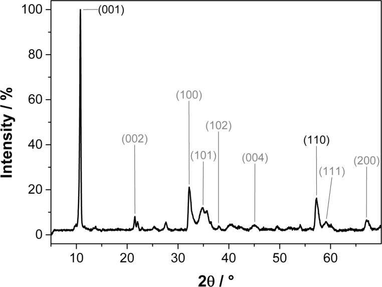
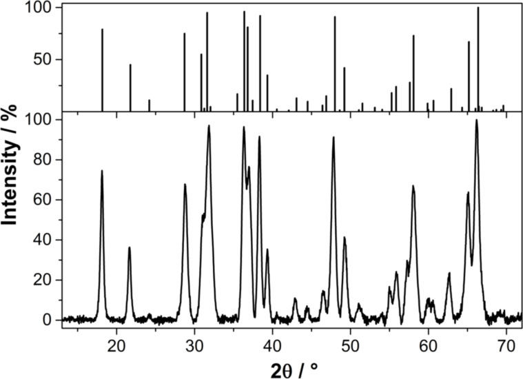
The polyol process reported by Liu et al. [19] was modified to yield the Mn(II) glycolate precursor for the thermal decomposition to the various manganese oxides. During the heating of the compound to 170 °C, a white precipitate appeared after 1 h, which was identified as manganese glycolate containing large impurities of the dehydrated educt Mn(II) acetate dihydrate and the product of a side reaction, manganese oxalate (MnC2O4, see Supporting Information File 1 for the powder XRD pattern of the product mixture). In order to obtain the pure Mn(II) glycolate precursor having homogeneous particle morphology, the reaction was continued at 170 °C until a white precipitate of pure Mn(II) glycolate appeared. This was verified by the X-ray diffraction pattern of the product after 7 h of synthesis as depicted in Figure 1. This product can be assigned to the trigonal brucite-type structure  reported for Mn(II) glycolate by other groups [19,29,35]. A mean Scherrer crystallite size of 17 ± 8 nm was calculated for the Mn(II) glycolate particles. The interlayer distance along the [001] direction was calculated to be 8.2 Å. This value corresponds to the lattice constant, c, and is consistent with reports by other groups who measured lattice constants of c = 8.3 Å and c = 8.27 Å for Mn and Co glycolate, respectively [34–35]. As Sun et al. [35] did not use tetraethylene glycolate (TEG) in their synthesis, it is proposed here that TEG anions are not part of the Mn(II) glycolate structure presented in this report, as c would be increased even beyond 8.2 Å in this case. Hence, it can be concluded that TEG acts only as a stabilizing ligand to the Mn(II) glycolate particles. This and the milder synthesis conditions applied are considered to be the reasons for the relatively small crystallite sizes, differing by one order of magnitude from the data presented to date in the literature [19,29,35]. Inorganic compounds with a brucite structure such as Mg(OH)2, Co(OH)2, Ca(OH)2 and Ni(OH)2, exhibit lattice constant c between 4.6 and 4.9 Å and a in the range from 3.1 to 3.6 Å. For Mn(II) glycolate, the Mn–Mn distance (corresponding to lattice constant a) was calculated to be 3.2 Å from the (110) reflection, which is also in accordance with the findings of Sun et al. [35] who proposed that the structure widening in the c direction is due to the long-chain alcoholate anions interconnecting the metal–oxygen sheets in the ab plane of the unit cell.
Figure 1.
Powder XRD pattern of Mn(II) glycolate particles synthesized for 7 h; literature assignments [35] (black) and calculated reflection assignments (grey) are given for the brucite structure exhibiting lattice constants of a = b = 3.2 Å and c = 8.2 Å.
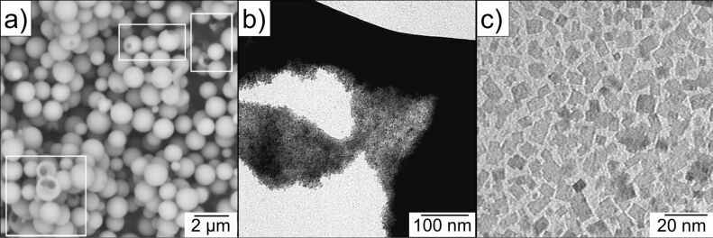
The morphology of the as-synthesized Mn(II) glycolate was investigated with SEM and TEM measurements. Figure 2a depicts SEM images of spherical Mn(II) glycolate particles with diameters up to 1 µm. These particles are hollow, which is deduced from the particles with broken outer shells (highlighted by white frames). Figure 2b shows a TEM image of one of these spherical particles, broken under the electron beam. A closer look reveals that the spheres are in fact agglomerates of rectangular Mn(II) glycolate nanoparticles with dimensions less than 15 nm (Figure 2c). The observed sizes of the particle are in good agreement with the calculated Scherrer crystallite sizes from the XRD pattern shown in Figure 1. The small dimensions of the particles make the synthesized Mn(II) glycolate a perfect precursor for the generation of manganese oxides by thermal decomposition processes.
Figure 2.
a) SEM and b) and c) TEM images of the Mn(II) glycolate particles. Particles with broken outer shells are highlighted by white frames in panel (a).
The oxidation process to different MnOx species
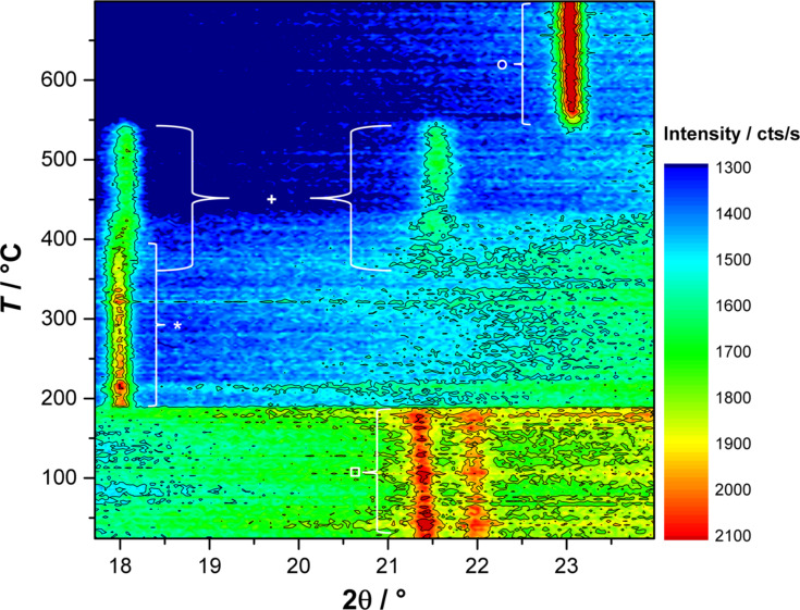
In order to investigate the temperature dependence of the oxidation process of Mn(II) glycolate, in situ X-ray diffractograms were recorded in the presence of O2 while heating the precursor to 700 °C at a heating rate of 2 K/min (see Figure 3). The 2θ region of 17.6–23.8° was monitored during the measurement, as it contains the reflections of the species that are most likely to be generated during the oxidation process (21.5° (Mn(II) glycolate, □) [19], 18.0° (Mn3O4, *) [36], 18.1° and 21.6° (Mn5O8, +) [31], and 23.2° (α-Mn2O3, ○) [37]). The reflection of Mn(II) glycolate at 21.5° is observed until a temperature of about 185 °C is reached, where a sudden decrease of the intensity (including the background intensity) is observed in the diffraction patterns due to the loss of organic species from the sample. This loss derives from the decomposition of the organic ligands and anions by oxidation; this is dependent on the temperature as well as on the partial pressure of oxygen. The Mn3O4 reflection at 18.0° immediately evolves at about 185 °C after the Mn(II) glycolate reflection has vanished. The appearance of the Mn5O8 reflection at 21.6° at about 350 °C is accompanied by the decreasing intensity of the Mn3O4 reflection at 18.0° as well as an increasing intensity of the Mn5O8 reflection at 18.1°, which is attributed to the slow oxidation of Mn3O4 to Mn5O8. The Mn3O4 reflection at 18.0° disappears at about 440 °C, indicating a completed oxidation process of Mn3O4 to Mn5O8. Both reflections assigned to Mn5O8 disappear at 550 °C after the appearance of the intense α-Mn2O3 reflection at 23.2° at a temperature of about 530 °C.
Figure 3.
In situ XRD patterns recorded in a pure O2 flow while heating the Mn(II) glycolate precursor to 700 °C at 2 K/min; reflexes denoted are: Mn(II) glycolate (□), Mn3O4 (*), Mn5O8 (+) and α-Mn2O3 (○).
Hence, in O2 atmosphere, Mn3O4 is obtained at temperatures between 185 and 400 °C, Mn5O8 between 400 and 550 °C and α-Mn2O3 above 530 °C. This oxidation of Mn3O4 to Mn5O8 (rather than to Mn2O3) was found by Feitknecht [30] to take place during the heating of Mn3O4 particles at temperatures between 250 and 550 °C in an atmosphere containing more than 5% O2. Feitknecht attributed this Mn3O4/Mn5O8 phase transformation to a one-phase mechanism for Mn3O4 particles exhibiting BET surface areas of more than 10 m2/g. That is, the small particle diameters provide sufficient reaction sites for oxidation of the surface of the particles. Feitknecht also reported similar reflection intensities for Mn3O4 and Mn5O8 with a linear decrease and increase, respectively, during the oxidation process. The subsequent reduction process of Mn5O8 to α-Mn2O3 was observed by several groups to take place even in oxygen-containing atmospheres at temperatures greater than 500 °C [26,32,37].
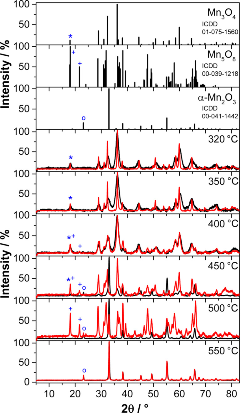
The Mn(II) glycolate particles were calcined for 2 h in Ar and O2 atmospheres at different temperatures between 320 and 550 °C to investigate the dependence of the particle size, their morphology and the Mnx+ oxidation state in the resulting manganese oxide on the calcination temperature and atmosphere. The X-ray diffractograms of the resulting species as well as the reference patterns are shown in Figure 4; the crystalline phases observed in the XRD patterns are listed in Table 1.
Figure 4.
Powder XRD patterns of the manganese oxide particles obtained after calcination of the Mn(II) glycolate for 2 h at different temperatures in an Ar (black) and an O2 (red) flow of 50 NL/h. Reference patterns are depicted at the top for Mn3O4 (*), Mn5O8 (+) and α-Mn2O3 (○), where the symbols indicate the respective low-angle reflections.
Table 1.
Crystalline manganese oxide phases obtained after calcination for 2 h in an Ar flow and an O2 flow (50 NL/h) at different temperatures; mean Scherrer crystallite sizes (from all assigned reflections) and lattice parameters (from the (101) and (004) reflections of Mn3O4 as well as the (400) reflection of α-Mn2O3) were calculated for samples yielding pure phases.
| Temperature [ °C] | Atmosphere | Crystalline phase(s) | Lattice parameters [Å] | Crystallite size [nm] |
| 320 | Ar | Mn3O4 |
a = 5.72 c = 9.38 |
11 ± 3 |
| O2 | Mn3O4 |
a = 5.75 c = 9.47 |
38 ± 11 | |
| 350 | Ar | Mn3O4 |
a = 5.69 c = 9.44 |
10 ± 3 |
| O2 | Mn3O4 |
a = 5.74 c = 9.47 |
35 ± 10 | |
| 400 | Ar | Mn3O4 |
a = 5.73 c = 9.39 |
9 ± 2 |
| O2 | Mn3O4, Mn5O8 | |||
| 450 | Ar | α-Mn2O3, Mn3O4 | ||
| O2 | Mn3O4, Mn5O8 | |||
| 500 | Ar | α-Mn2O3 | a = 9.41 | 27 ± 4 |
| O2 | Mn5O8, α-Mn2O3 | |||
| 550 | Ar | α-Mn2O3 | a = 9.40 | 34 ± 5 |
| O2 | α-Mn2O3 | a = 9.41 | 44 ± 12 | |
The tetragonal Mn3O4 phase (ICDD 01-075-1560, I41/amd) is observed in the powder XRD patterns after calcination at temperatures between 320 and 450 °C in both atmospheres. It is, however, obtained as a pure phase only at temperatures up to 400 °C in Ar and up to 350 °C in O2 (see also Table 1). The presence of Mn3O4 in O2 atmosphere could also be observed in the in situ XRD measurements up to a temperature of 440 °C (see Figure 3). The lattice parameters and crystallite sizes of the pure Mn3O4 samples obtained by calcination in Ar as well as O2 atmospheres at 320 °C and 350 °C listed in Table 1 are obviously independent of the calcination temperature, but dependent on the calcination atmosphere. The samples obtained in Ar exhibit crystallite sizes of less than a third compared to those obtained in O2. Furthermore, the lattice constants of Mn3O4 produced in Ar are smaller at all temperatures than those obtained by calcination in O2 atmosphere. This could be due to oxygen vacancies, as the oxygen for the oxidation to Mn3O4 in pure Ar is only supplied by the manganese glycolate precursor and cannot be obtained from the gas atmosphere. The presence of oxygen vacancies is also supported by the less pronounced variation of the lattice constants of Mn3O4 obtained at 320 °C and 350 °C in O2 atmospheres, leading to the assumption of completely occupied oxygen sites in the structure of the oxide.
Cubic α-Mn2O3 (ICDD 00-041-1442,  ) is obtained in Ar after calcination at temperatures between 450 and 550 °C and at 500–550 °C in O2. Pure-phase α-Mn2O3, however, is only obtained after calcination at temperatures of 500 and 550 °C in Ar and at 550 °C in O2 atmospheres (see also Table 1). The presence of α-Mn2O3 after calcination at 500 °C in O2 does not support the observations made in the in situ XRD measurements (compare to Figure 3), where a generation of α-Mn2O3 from Mn5O8 in an O2 atmosphere was only detected at temperatures above 530 °C. However, this is probably due to an additional time dependence of the phase transformation of Mn5O8 to α-Mn2O3, which was also suggested by Dimesso et al. [28]. In their report the α-Mn2O3 phase was observed to be the minor species second to Mn5O8 after calcination at 400 °C in air for 1 h, but was found to be the major species after calcination for 5 h at the same temperature. The lattice constants of the pure α-Mn2O3 phase obtained after calcination in Ar and O2, are obviously independent of the temperature and the calcination atmosphere (see Table 1). Therefore, in contrast to the observations made for Mn3O4, the absence of O2 in the calcination atmosphere does not lead to an increase in the concentration of oxygen vacancies in the α-Mn2O3 structure, which would be high enough to significantly change the lattice constants. The values of the Scherrer-derived crystallite sizes, however, suggest a temperature dependence of the obtained α-Mn2O3 particle size in Ar atmosphere, which was not the case for the Mn3O4 particles. The Scherrer-derived size of the crystallites of the pure phase α-Mn2O3 obtained in an O2 atmosphere at 550 °C is one third larger than that calculated for particles obtained in Ar at the same temperature. Hence, similar to the Mn3O4 phases described above, the presence of O2 in the calcination atmosphere yields larger crystallites of the same product.
No pure phase of monoclinic Mn5O8 (ICDD 00-039-1218, C2/m) could be obtained by calcination at temperatures between 320 and 550 °C for 2 h in both atmospheres. However, after calcination in O2 atmosphere, a small fraction of Mn5O8 can be detected in the products obtained at 400 and 450 °C, while it forms the majority of the product obtained after calcination at 500 °C. This is in good agreement with the in situ XRD patterns recorded in O2 atmosphere, where Mn5O8 was generated at about 350 °C and decomposed at 550 °C (see Figure 3).
In order to obtain pure-phase Mn5O8 particles, a longer calcination time of 5 h at 400 °C in an O2 atmosphere was chosen based on the time profile from the in situ XRD measurements (see Supporting Information File 1 for further details).
The properties of the Mn5O8 sample were investigated in more detail and compared to those of the Mn3O4 and α-Mn2O3 samples obtained by calcination for 2 h in Ar at 350 °C and at 550 °C, respectively. These Mn3O4 and α-Mn2O3 samples were chosen as they exhibit the most interesting properties for possible catalytic applications due to their small particle sizes.
The X-ray diffraction pattern of pure Mn5O8 obtained by calcination in an O2 atmosphere at 400 °C for 5 h is shown in Figure 5. The Scherrer-derived crystallite size of this species is 22 ± 5 nm, and the lattice parameters of the monoclinic unit cell (ICDD 00-039-1218) are a = 10.40 Å, b = 5.73 Å and c = 4.87 Å with β = 109.6°, which is in good agreement with the data from literature (a = 10.34 Å, b = 5.72 Å and c = 4.85 Å with β = 109.25°) [31].
Figure 5.
Powder XRD patterns of the Mn5O8 particles obtained by calcination of Mn(II) glycolate for 5 h at 400 °C in an O2 flow of 50 NL/h; a reference pattern is given in the top panel (ICDD 00-039-1218).
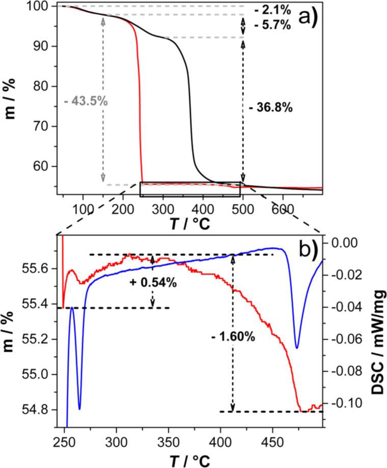
The temperature- and gas atmosphere-dependent oxidation process of Mn(II) glycolate to the manganese oxide species observed in the XRD patterns (see Figure 3 and Figure 4) was also investigated by thermogravimetric analysis (TGA). TGA measurements were recorded while heating the Mn(II) glycolate samples up to 700 °C with a heating rate of 2 K/min in an Ar (black) and an O2/Ar (1:2) (red) flow, respectively.
In both atmospheres a mass loss of 2.1% due to loss of water from the samples is detected up to a temperature of 150 °C. In Ar atmosphere, a further mass loss of 5.7% occurs up to 320 °C, which we attribute to the decomposition of the organic ligands (tetraethylene glycol and ethylene glycol), whose boiling points are in the temperature range of 150 °C to 320 °C. Subsequently, a mass loss of about 37% is detected up to 450 °C, which was also observed in TGA measurements of Ti(IV) glycolate by Jiang et al. [38] and was explained as a complete decomposition of the organic anions connecting the metal ions in that compound. Simultaneously, Mn(II) glycolate is oxidized to Mn3O4 and further to α-Mn2O3 between 185 °C to 450 °C, as was observed in the XRD measurements after calcination of the precursor for 2 h, as discussed above (see Figure 4). Although this oxidation process is accompanied by a decomposition of the organic groups, XPS results showed the presence of approximately 25 atom % carbon in the α-Mn2O3 species obtained after calcination for 2 h at 550 °C in Ar atmosphere. This, however, will not have a significant effect on its application as an electrocatalyst, as the reference and substrate material for the catalysts consists of carbon.
The decomposition of the organic species of Mn(II) glycolate in combination with an immediate oxidation to Mn3O4 in O2 atmosphere was observed at 185 °C in the in situ XRD measurement depicted in Figure 3. In the TGA measurement, however, a mass loss of 44% attributed to this process is detected between 150 and 250 °C. Hence, the observed mass loss includes the decomposition of organic species as well as the oxidation to Mn3O4. The temperature delay of the processes can be explained by considering the smaller O2 partial pressure of the atmosphere used for the TGA measurement. As both processes take place simultaneously, a clear assignment of the weight loss cannot be made. In order to investigate the processes subsequent to the large mass loss in the O2-containing atmosphere, a detailed view of the temperature region from 250 to 500 °C is shown in Figure 6b. Here, a mass increase of 0.54% is observed between 250 and 330 °C accompanied by a differential scanning calorimetry (DSC) signal of an exothermal phase transformation at 270 °C indicating a partial oxidation of Mn3O4 to Mn5O8. This is in good agreement with the development of the Mn5O8 phase observed at about 350 °C in the in situ XRD measurements (see Figure 3). The expected mass gain by complete oxidation to Mn5O8 of 5.59% is, however, much larger. Gillot et al. [27] proposed that heating rates between 1.2 and 2.5 K/min could lead to a direct oxidation of Mn3O4 to α-Mn2O3 even in O2 atmosphere, which would result in an expected mass gain of 0.97%. As both the direct oxidation of Mn3O4 to α-Mn2O3 and the oxidation via Mn5O8 would result in larger mass increases than the one observed in the measurement (0.54%), it is suggested that the decomposition of the organic species is not complete at a temperature of 330 °C. However, the subsequent mass loss of 1.60% from 330 to 480 °C, a DSC signal of an exothermal phase transformation at 480 °C, and the XRD measurements presented in this report (see Figure 3 and Figure 4) indicate the presence of Mn5O8. This mass loss again is lower than the expected value of 2.03% for a complete conversion of Mn5O8 to α-Mn2O3, which indicates that less α-Mn2O3 is formed from Mn5O8 than expected. Hence, in an O2/Ar atmosphere, α-Mn2O3 is generated partially from Mn5O8 and partially by direct oxidation from Mn3O4.
Figure 6.
a) TGA measurements recorded while heating the Mn(II) glycolate precursor up to 700 °C at 2 K/min in an Ar (black) and an O2/Ar (1:2) (red) flow of 40 NmL/min; b) detailed view of the temperature range between 250 and 500 °C of the TGA (red) and DSC (blue) measurements in O2/Ar (1:2) flow indicating the oxidation of Mn3O4 to Mn5O8 and α-Mn2O3.
The increase and decrease in mass in the presence of gaseous O2 was proposed to be due to slow seed crystal oxidation of Mn3O4 to Mn5O8 for particles with BET surfaces larger than 10 m2/g and their subsequent transformation to α-Mn2O3 [29–30].
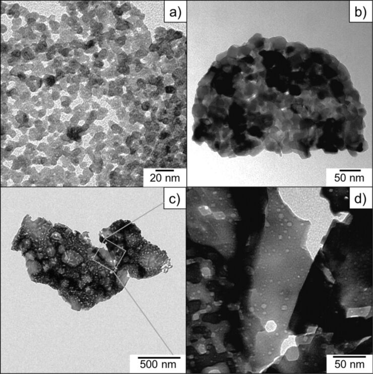
In order to characterize the size of the particles and the active surface areas, pure Mn3O4, Mn5O8 and α-Mn2O3 species obtained by calcination of the Mn(II) glycolate precursor at temperatures of 350, 400 and 550 °C were characterized by TEM and BET measurements. The TEM images of the Mn3O4 and Mn5O8 samples are shown in Figure 7a,b; the sizes of the particles observed in TEM are in good agreement with the Scherrer-derived crystallite sizes calculated from the XRD patterns (see Figure 4 for comparison). The Mn3O4 sample shown in Figure 7a consists of a network of nanoparticles with diameters less than 10 nm and voids between the particles of about the same size. The same is true for the Mn5O8 sample in Figure 7b, but here the nanoparticles with diameters of up to 30 nm are obviously packed more densely. We attribute this to the increased temperature and duration of the calcination process, as well as to the presence of O2 in the atmosphere, which leads to larger particles, as previously discussed (see discussion for Figure 4). The α-Mn2O3 sample obtained by calcination in an Ar atmosphere (see Figure 7c,d), however, contains splinter-like pieces in the µm range (approximately 1–2 µm in the given TEM image) with a high concentration of holes with diameters of up to 20 nm, rather than individual nanoparticles. This manner of porosity for α-Mn2O3 was also confirmed by N2 adsorption–desorption measurements (see Figure 8). Mesoporosity in hexagonally shaped α-Mn2O3 particles and circular Mn2O3 discs obtained by calcination at temperatures above 600 °C was reported by several groups [17,37]. Ren et al. suggested that the mesopores are derived from a sequence of processes including Mn5O8 nanoparticle growth, rearrangement and merging during the transformation to α-Mn2O3 [37]. As the phase of Mn5O8 was not observed after calcination in Ar atmosphere, we propose that the presence of pores in the α-Mn2O3 particles reported here results from the analog growth, rearrangement and merging processes of the Mn3O4 nanoparticles.
Figure 7.
TEM images of the a) Mn3O4, b) Mn5O8, and c) and d) α-Mn2O3 samples.
Figure 8.
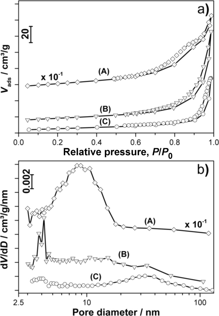
a) N2 adsorption–desorption isotherms (volume adsorbed versus relative pressure, P/P0) and b) the corresponding pore size distributions of the (A) Mn3O4, (B) Mn5O8 and (C) α-Mn2O3 samples.
The considerably smaller size of the crystallites obtained from the broadening of the XRD reflections of α-Mn2O3 is another argument for the porosity of these particles, as the pore walls in this case represent boundaries of the crystalline domains. Because these domains are regarded as Scherrer crystallites, we conclude that the obtained sizes are the mean distances between the pores as well as the minimum diameter of the α-Mn2O3 particles.
From the isotherms recorded during N2 adsorption–desorption measurements (see Figure 8a) specific BET surface areas of 302, 30 and 20 m2/g were calculated for the Mn3O4, Mn5O8 and α-Mn2O3 samples, respectively. The porosity of the α-Mn2O3 particles observed in the TEM images (see Figure 7c,d) is also supported by the N2 adsorption–desorption isotherms, which exhibit hysteresis. As hysteresis is also observed in the Mn3O4 and Mn5O8 nanoparticle isotherms (but not supported by observations made in the TEM images for these species, see Figure 7a,b), two different definitions of porosity can be applied for the different manganese oxide species. The pore size distributions depicted in Figure 8b show a pore diameter distribution between 3 and 20 nm with a mean pore diameter of 8.2 nm for the Mn3O4 sample. The porosity of the Mn3O4 nanoparticles can be explained by considering the voids between the particles in the network as the “pores” detected in the N2 adsorption–desorption measurements. This assumption is in good agreement with the similar sizes of the voids and nanoparticles observed in the TEM image (compared with Figure 7a). The same “pore definition” can be applied to the Mn5O8 sample exhibiting pore sizes between 3 and 5 nm with a comparably small mean pore size of 4.2 nm, probably due to the dense network of the particles observed in the TEM image (compared to Figure 7b). The α-Mn2O3 sample does not contain nanoparticles, but exhibits a pore size distribution between 3 and 5 nm as well as 10 and 90 nm with a mean diameter of 32.6 nm. In accordance with the TEM images (see Figure 7c,d for comparison) and the lowest BET surface area of all the samples, these pores do not derive from voids in the nanoparticle network but rather from the mesoporosity of the splinter-like pieces. A surface area of approximately 20 m2/g and pore diameters from 4 to 7 nm were also reported for Mn2O3 discs synthesized for the use as electrode material by Zhang et al. [17]. However, we believe a larger pore size to be advantageous for application as electrocatalysts, as electrochemical processes often produce solid products, which might easily clog pores in the micro- and meso-porous range.
The specific surface areas of Mn3O4 and Mn5O8 are in good agreement with the sizes of the particles observed in the TEM images and calculated from the XRD patterns, as smaller particles generally exhibit larger surface areas. However, the α-Mn2O3 particles, which are one order of magnitude larger, exhibit a high specific BET surface area comparable to that of the Mn5O8 nanoparticles. Two explanations for this large specific surface are proposed: the lower molar weight of α-Mn2O3 compared to Mn5O8 (resulting in a larger specific surface area), and the mesoporosity of the α-Mn2O3, which was already observed in the TEM images (see Figure 7c,d).
Electrocatalytic activities of the MnOx species
In order to investigate the electrocatalytic activity of the synthesized MnOx species for the oxygen reduction reaction (ORR), linear sweep measurements were carried out.
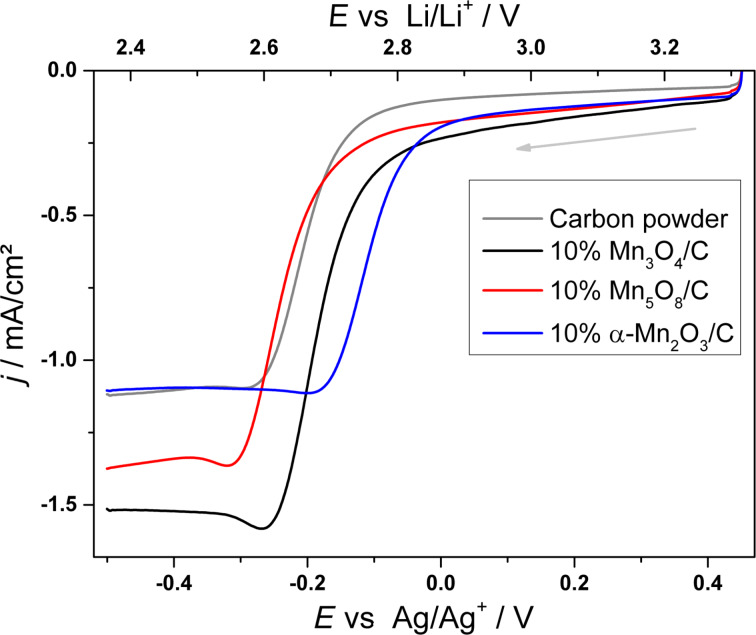
Figure 9 shows linear sweep measurements recorded at 50 mV/s comparing the activity of various 10% MnOx/carbon electrodes to a pure carbon electrode as a reference material for the ORR in aprotic electrolyte. The ORR peak potentials as well as the apparent reaction rate constant,  , for the different electrode materials are summarized in Table 2. The reaction rate constant was calculated from:
Figure 9.
Linear sweep voltammograms of pure carbon powder (grey), Mn3O4/C (black), Mn5O8/C (red) and α-Mn2O3/C (blue) electrodes; electrolyte: 1 M LiTFSI/DMSO, cathodic scan direction, ν = 50 mV/s, ω = 200 rpm.
Table 2.
ORR potentials and reaction rate constants obtained from the linear sweep measurements recorded at ν = 50 mV/s.
| Epeak vs Li/Li+ [V] |
 [10−4 cm/s] [10−4 cm/s] |
|
| Carbon (C) | 2.58 ± 0.02 | 1.2 ± 1.1 |
| Mn3O4/C | 2.58 ± 0.08 | 2.6 ± 1.3 |
| Mn5O8/C | 2.58 ± 0.07 | 2.7 ± 2.3 |
| α-Mn2O3/C | 2.68 ± 0.05 | 4.5 ± 2.5 |
| [1] |
where j0 is the cathodic exchange current density (obtained from the Tafel plots of the linear sweep measurements), n = 1 is the number of transferred electrons, F is the Faraday constant, and CO2 = 2.1∙10−6 mol cm−3 is the oxygen solubility in DMSO [39].
The mean ORR peak potential of the carbon reference material given in Table 2 is observed at 2.58 V. The only MnOx species with a significant increase of the ORR potential of 100 mV with respect to the carbon as well as the other MnOx/C electrodes is the mesoporous α-Mn2O3 catalyst. The obvious activity is reflected in the approximately four- and two-fold larger apparent ORR rate constant  compared to the carbon and the other MnOx/C electrodes, respectively.
A detailed kinetic and mechanistic study on the electrocatalytic activities of the different MnOx species for the aprotic oxygen reduction reaction is reported elsewhere [40].
Conclusion
In summary, a polyol synthesis was presented yielding rectangular, Mn(II) glycolate nanoparticles with dimensions of 17 ± 8 nm. Particle sizes of less than 100 nm are reported here for the first time. We attribute this small size of the particles to the stabilizing tetraethylene glycol ligand used during the synthesis, as well as milder reaction conditions compared with other reports (i.e., a decreased temperature and a longer reaction time). In situ XRD measurements showed the sequence of time- and temperature-dependent phase transformations during oxidation of the Mn(II) glycolate precursor to α-Mn2O3 via Mn3O4 and Mn5O8 in O2 atmosphere. Structural and morphological investigations revealed the dependence of the lattice constants and particle sizes of the MnOx species on the calcination temperatures in a range from 320 to 550 °C as well as on Ar and O2 atmospheres. Based on the results of these measurements, several manganese oxide species were synthesized by calcination of Mn(II) glycolate particles in argon and oxygen atmosphere at different temperatures. The calcination process yielded Mn3O4 nanoparticles with dimensions of about 10 nm and a surface area of 302 m2/g, Mn5O8 nanoparticles with diameters of 22 nm and a surface area of 30 m2/g as well as mesoporous α-Mn2O3 particles with mean pore diameters of about 33 nm and a surface area of 20 m2/g. The small dimensions of the particles and large surface areas of the manganese oxides presented here result from use of nanostructured precursor particles. Linear sweep measurements showed the activity of the mesoporous α-Mn2O3 species for the oxygen reduction reaction in aprotic media with respect to the observed potentials as well as an enhanced kinetic activity. The catalytic activity of different manganese oxides can be enhanced by a larger surface area, resulting from small particle dimensions or mesoporosity. This makes our synthesis a suitable process to obtain manganese oxides having properties of particular interest for electrochemical and chemical catalysis. Furthermore, the synthesis of manganese oxides via one route reported here is of additional interest, as it excludes any synthesis-caused effects on the products and allows investigation on the catalytic effect of similarly synthesized manganese oxides with different properties.
Experimental
Materials
Manganese(II) acetate tetrahydrate (MnAc2, >99%, pure) and ethylene glycol (EG, >99.5%, p.a.) were purchased from Carl-Roth. Tetraethylene glycol (TEG, 99%) was delivered by Sigma-Aldrich. For the electrode preparation, a 10 wt % Nafion®/water solution was purchased from Sigma-Aldrich, analytical reagent-grade ethanol from Fisher Scientific, and Vulcan® XC72R carbon powder was obtained from Cabot. For electrochemical measurements, reagent-grade lithium bis(trifluoromethylsulfonyl)imide (LiTFSI) was purchased from Merck KGaA and dimethyl sulfoxide (DMSO, anhydrous, ≥99.9%) from Sigma-Aldrich. All chemicals were used without further purification.
Synthesis of Mn(II) glycolate
In a typical reaction, 1 mmol (0.246 g) MnAc2 was mixed with 3 mmol (3 mL) TEG and added to 30 mL EG in a three-neck round-bottom flask. The solution was heated to 170 °C while stirring. Upon heating, the solution turned brown at a temperature of about 110 °C, and after further heating for about 1 h at 170 °C, a white precipitate appeared that disappeared again after 1 h. The solution was stirred for another 4 h at 170 °C until a white precipitate appeared again which indicated the formation of the Mn(II) glycolate particles. The product was stirred for another hour at 170 °C to complete the reaction and was subsequently cooled down to room temperature. The white powder was centrifuged and washed at least five times with ethanol to remove any impurities. Subsequently, the white product was dried under Ar flow.
Synthesis of Mn3O4, Mn5O8 and α-Mn2O3
The obtained Mn(II) glycolate powder was calcined in an Ar flow of 50 NL/h for 2 h at 350 °C and at 550 °C yielding Mn3O4 and α-Mn2O3, respectively. Mn5O8 was obtained by calcination of the precursor in an O2 flow of 50 NL/h for 5 h at 400 °C.
Characterization methods
Transmission electron microscopy (TEM) was carried out with a Zeiss EM 902A microscope with an acceleration voltage of 80 kV. For high resolution TEM (HR-TEM) measurements a JEOL JEM2100F microscope with an acceleration voltage of 200 kV was used. The samples for TEM and HR-TEM measurements were prepared by depositing a drop of an ethanol emulsion of the powder on a carbon-coated copper grid and drying at room temperature.
Scanning electron microscopy (SEM) was carried out with an Oxford INCA system employing a PentaFET Precision INCA X-act detector integrated into the Hitchai S-3200N microscope. The sample was prepared by depositing an ethanol emulsion of the sample onto an Al substrate and drying at room temperature.
For X-ray diffraction (XRD), a PANalytical X’Pert Pro MPD diffractometer was used operating with Cu Kα radiation, Bragg-Brentano θ-2θ geometry and a goniometer radius of 240 mm. Samples for XRD measurements were prepared by placing the powder onto low-background silicon sample holders. Different atmospheres were used as mentioned in the text. The crystallite sizes of the samples were calculated from all assigned reflections via the Scherrer equation. The lattice parameters were obtained with the Bragg equation from assigned diffraction reflections.
In situ XRD measurements were performed in the same geometry using a high temperature chamber from Anton Paar (HTK 1200N). The temperature profile measurement was recorded while heating the powder sample from 25 to 700 °C with a heating rate of 2 K/min. The time profile measurement (shown in Supporting Information File 1) was conducted by heating the powder sample from 25 to 400 °C with a heating rate of 18 K/min and subsequent constant heating at 400 °C for 350 min. The powder sample was placed on a corundum sample holder. During the measurement the thermal expansion was corrected automatically. The measurements were performed in an O2 flow.
Thermogravimetric analysis (TGA) and differential scanning calorimetry (DSC) were carried out with a Netzsch STA 449 F3 Jupiter thermo-analysis system. The sample was deposited in an Al2O3 crucible and heated from 35 to 700 °C with a heating rate of 2 K/min in an O2(6.0)/Ar(5.0) (1:2) and an Ar(5.0) gas flow of 40 NmL/min.
The porosity of the manganese oxides was determined by N2 adsorption–desorption measurements. Prior to the measurement, the material was kept for 18 h at 180 °C under vacuum to remove any residual gas and moisture from the sample. The adsorption–desorption isotherms were measured employing a Quantachrome Nova 2000E device at 77 K. The Brunauer–Emmet–Teller (BET) method was used to determine the complete inner surfaces S0 and the Barrett–Joyner–Halenda (BJH) method for mesopore surface analysis as well as the determination of pore size distributions.
Electrode preparation
The catalyst/carbon ink for the powder electrodes was prepared by mixing and grinding 90 mg Vulcan® XC72R carbon powder with 10 mg of MnOx catalyst. This active material was dispersed in ethanol and ultrasonicated for 20 min. As a binder material, 0.1 wt % Nafion/water solution was added to the catalyst/carbon paste and ultrasonicated for another 20 min. A 10 µL drop of the ink was applied on a glassy carbon disc (d = 0.5 cm) and dried for 12 h at 80 °C. The 10 wt % catalyst loading of the prepared electrodes equals 4.8 µg per electrode or 24.4 µg cm−2.
Electrochemical measurements
For linear sweep voltammetry measurements, a Gamry Instruments Reference 600 Potentiostat was used. The measurements were carried out on a rotating disc electrode (RDE) in a glove box in Ar atmosphere at ambient temperature. For the electrochemical setup, glassy carbon (Pine Research Instrumentation, electrode model no. AFE3T050GC) and carbon/catalyst-coated glassy carbon discs (see above) served as working electrodes. A polished Ag wire and a Pt disc were used as reference and counter electrodes, respectively. 1 M LiTFSI/DMSO was used as the electrolyte, which was saturated with pure O2 for 25 min before the start of the measurement. The linear sweep measurements were recorded at a scan rate of ν = 50 mV/s and a rotational frequency of ω = 200 rpm.
Supporting Information
The supporting information features the powder XRD pattern of Mn(II) glycolate particles after 1 h of synthesis at 170 °C in addition to in situ XRD patterns of the time-dependent oxidation of Mn3O4 to Mn5O8 at 400 °C in O2.
Additional XRD experimental data.
Acknowledgments
We thank Magdalena Bogacka for conducting the TGA/DSC measurements. We gratefully acknowledge the funding of the EWE Research Group “Thin Film Photovoltaics” by the EWE AG, Oldenburg, Germany, as well as funding by the government of Lower Saxony (Germany).
This article is part of the Thematic Series "Nanostructures for sensors, electronics, energy and environment II".
References
- 1.Owens B B, Passerini S, Smyrl W H. Electrochim Acta. 1999;45:215–224. doi: 10.1016/S0013-4686(99)00205-4. [DOI] [Google Scholar]
- 2.Park K-W. J Mater Chem A. 2014;2:4292–4298. doi: 10.1039/c3ta14223j. [DOI] [Google Scholar]
- 3.Xu M-W, Niu Y-B, Bao S-J, Li C M. J Mater Chem A. 2014;2:3749–3755. doi: 10.1039/c3ta14211f. [DOI] [Google Scholar]
- 4.Gil A, Gandía L M, Korili S A. Appl Catal, A. 2004;274:229–235. doi: 10.1016/j.apcata.2004.07.004. [DOI] [Google Scholar]
- 5.Mellan T A, Maenetja K P, Ngoepe P E, Woodley S M, Catlow C R A, Grau-Crespo R. J Mater Chem A. 2013;1:14879–14887. doi: 10.1039/c3ta13559d. [DOI] [Google Scholar]
- 6.Feng Q, Kanoh H, Ooi K. J Mater Chem. 1999;9:319–333. doi: 10.1039/a805369c. [DOI] [Google Scholar]
- 7.Kapteljn F, Singoredjo L, Andreini A, Moulijn J A. Appl Catal, B: Environ. 1994;3:173–189. doi: 10.1016/0926-3373(93)E0034-9. [DOI] [Google Scholar]
- 8.Xiao J, Wan L, Wang X, Kuang Q, Dong S, Xiao F, Wang S. J Mater Chem A. 2014;2:3794–3800. doi: 10.1039/c3ta14453d. [DOI] [Google Scholar]
- 9.Su H-Y, Gorlin Y, Man I C, Calle-Vallejo F, Nørskov J K, Jaramillo T F, Rossmeisl J. Phys Chem Chem Phys. 2012;14:14010–14022. doi: 10.1039/c2cp40841d. [DOI] [PubMed] [Google Scholar]
- 10.Ramírez A, Friedrich D, Kunst M, Fiechter S. Chem Phys Lett. 2013;568–569:157–160. doi: 10.1016/j.cplett.2013.03.054. [DOI] [Google Scholar]
- 11.Najafpour M M, Rahimi F, Amini M, Nayeri S, Bagherzadeh M. Dalton Trans. 2012;41:11026–11031. doi: 10.1039/c2dt30553d. [DOI] [PubMed] [Google Scholar]
- 12.Ogasawara T, Débart A, Holzapfel M, Novák P, Bruce P G. J Am Chem Soc. 2006;128:1390–1393. doi: 10.1021/ja056811q. [DOI] [PubMed] [Google Scholar]
- 13.Débart A, Bao J, Armstrong G, Bruce P G. J Power Sources. 2007;174:1177–1182. doi: 10.1016/j.jpowsour.2007.06.180. [DOI] [Google Scholar]
- 14.Giordani V, Freunberger S A, Bruce P G, Tarascon J-M, Larcher D. Electrochem Solid-State Lett. 2010;13:A180–A183. doi: 10.1149/1.3494045. [DOI] [Google Scholar]
- 15.Cheng H, Scott K. Appl Catal, B: Environ. 2011;108–109:140–151. doi: 10.1016/j.apcatb.2011.08.021. [DOI] [Google Scholar]
- 16.Jung K-N, Riaz A, Lee S-B, Lim T-H, Park S-J, Song R-H, Yoon S, Shin K-H, Lee J-W. J Power Sources. 2013;244:328–335. doi: 10.1016/j.jpowsour.2013.01.028. [DOI] [Google Scholar]
- 17.Zhang Y, Yan Y, Wang X, Li G, Deng D, Jiang L, Shu C, Wang C. Chem – Eur J. 2014;22:6126–6130. doi: 10.1002/chem.201304935. [DOI] [PubMed] [Google Scholar]
- 18.Lei S, Tang K, Fang Z, Liu Q, Zheng H. Mater Lett. 2006;60:53–56. doi: 10.1016/j.matlet.2005.07.070. [DOI] [Google Scholar]
- 19.Liu L, Yang Z, Liang H, Yang H, Yang Y. Mater Lett. 2010;64:891–893. doi: 10.1016/j.matlet.2010.01.054. [DOI] [Google Scholar]
- 20.Azzoni C B, Mozzati M C, Galinetto P, Paleari A, Massarotti V, Capsoni D, Bini M. Solid State Commun. 1999;112:375–378. doi: 10.1016/S0038-1098(99)00368-3. [DOI] [Google Scholar]
- 21.Cushing B L, Kolesnichenko V L, O’Connor C J. Chem Rev. 2004;104:3893–3946. doi: 10.1021/cr030027b. [DOI] [PubMed] [Google Scholar]
- 22.Gui Z, Fan R, Mo W, Chen X, Yang L, Hu Y. Mater Res Bull. 2003;38:169–176. doi: 10.1016/S0025-5408(02)00983-2. [DOI] [Google Scholar]
- 23.Javed Q, Feng-Ping W, Rafique M Y, Toufiq A M, Iqbal M Z. Chin Phys B. 2012;21:117311–117317. doi: 10.1088/1674-1056/21/11/117311. [DOI] [Google Scholar]
- 24.Yuan Z-Y, Ren T-Z, Du G, Su B-L. Chem Phys Lett. 2004;389:83–86. doi: 10.1016/j.cplett.2004.03.064. [DOI] [Google Scholar]
- 25.Liu L, Yang H, Wei J, Yang Y. Mater Lett. 2011;65:694–697. doi: 10.1016/j.matlet.2010.11.042. [DOI] [Google Scholar]
- 26.Dhaouadi H, Ghodbane O, Hosni F, Touati F. ISRN Spectrosc. 2012;2012:1–8. doi: 10.5402/2012/706398. [DOI] [Google Scholar]
- 27.Gillot B, El Guendouzi M, Laarj M. Mater Chem Phys. 2001;70:54–60. doi: 10.1016/S0254-0584(00)00473-9. [DOI] [Google Scholar]
- 28.Dimesso L, Heider L, Hahn H. Solid State Ionics. 1999;123:39–46. doi: 10.1016/S0167-2738(99)00107-1. [DOI] [Google Scholar]
- 29.Larcher D, Sudant G, Patrice R, Tarascon J. Chem Mater. 2003;15:3543–3551. doi: 10.1021/cm030048m. [DOI] [Google Scholar]
- 30.Feitknecht W. Pure Appl Chem. 1964;9:423–440. doi: 10.1351/pac196409030423. [DOI] [Google Scholar]
- 31.Oswald H R, Wampetich M J. Helv Chim Acta. 1967;50:2023–2034. doi: 10.1002/hlca.19670500736. [DOI] [Google Scholar]
- 32.Punnoose A, Magnone H, Seehra M S. IEEE Trans Magn. 2001;37:2150–2152. doi: 10.1109/20.951107. [DOI] [Google Scholar]
- 33.Thota S, Prasad B, Kumar J. Mater Sci Eng, B. 2010;167:153–160. doi: 10.1016/j.mseb.2010.01.049. [DOI] [Google Scholar]
- 34.Chakroune N, Viau G, Ammar S, Jouini N, Gredin P, Vaulay M J, Fiévet F. New J Chem. 2005;29:355–361. doi: 10.1039/b411117f. [DOI] [Google Scholar]
- 35.Sun Y, Hu X, Luo W, Huang Y. J Mater Chem. 2012;22:19190–19195. doi: 10.1039/c2jm32036c. [DOI] [Google Scholar]
- 36.Aminoff G. Z Kristallogr, Kristallgeom, Kristallphys, Kristallchem. 1926;64:475–490. [Google Scholar]
- 37.Ren T-Z, Yuan Z-Y, Hu W, Zou X. Microporous Mesoporous Mater. 2008;112:467–473. doi: 10.1016/j.micromeso.2007.10.025. [DOI] [Google Scholar]
- 38.Jiang X, Wang Y, Herricks T, Xia Y. J Mater Chem. 2004;14:695–703. doi: 10.1039/b313938g. [DOI] [Google Scholar]
- 39.Sawyer D T, Chiericato G, Jr, Angells C T, Nanni E J, Jr, Tsuchiya T. Anal Chem. 1982;54:1720–1724. doi: 10.1021/ac00248a014. [DOI] [Google Scholar]
- 40.Augustin, M.; Yezerska, O.; Fenske, D.; Bardenhagen, I.; Westphal, A.; Knipper, M.; Plaggenborg, T.; Kolny-Olesiak, J.; Parisi, J. Electrochim. Acta 2014, submitted.
Associated Data
This section collects any data citations, data availability statements, or supplementary materials included in this article.
Supplementary Materials
Additional XRD experimental data.


