

1. Introduction
In an experiment performed nearly 30 years ago that involved laser desorption of graphite a substrate followed by plume cooling in the He carrier gas and mass analysis of the generated ionic clusters, a new form of carbon, a fullerene, was conceived.1 An equally important discovery of the bulk synthesis of fullerenes, via arc discharge of graphite, was made by Huffman and Krätschmer in 1990.2 These two discoveries of the nearly spherical Ih-C60 molecule, with a 1 nm diameter, marked the beginning of nanoscience, a vibrant field of multidisciplinary research and cutting-edge modern technology.
The past 25 years of flourishing fullerene research have resulted in many thousands of new chemical materials, true technological breakthroughs, and a lot of promise that is yet to be met in the practical world. What remains constant throughout the relatively short history of fullerene chemistry (cf., 200-year old chemistry of benzene) is the unsurpassed richness and diversity of chemical transformations and continued unprecedented dedication of scores of researchers to the field that is frequently rewarded by newly discovered reaction mechanism or unexpected functions of their molecular designs with fullerenes.
Several excellent books, series of conference proceedings volumes, a specialized journal, dedicated journal issues, and tens of thousands of original articles were published since 1985. More recently, comprehensive general reviews on various aspects of fullerene chemistry have been published in Chemical Reviews.3
The scope of this Review is the first attempt to provide a general and in-depth overview of the research activity in the field of perfluoroalkylation of fullerenes that occurred in 1993–2014. The authors of this work are a team of very close collaborators from three scientific generations who have continuously worked in this field since 2001, and some of us were involved in fullerene research as early as Fall 1992.
Even though perfluoroalkylfullerenes (PFAFs) may appear at first sight as a too-specialized group of fullerene compounds in the diverse and vast library of fullerenes, we are convinced that such a focused and detailed review is warranted and timely. First, PFAFs represent by far the largest single family of fullerene derivatives with multiple additions that have well-defined molecular structures, systematically measured fundamental physical properties, and theoretically determined relative stabilities, frontier orbital energies, and molecular geometries. This wealth and breadth of data allowed for in-depth analysis of the structure–property relationship for many dozens of compounds that led to the formulations of the general reactivity and structural principles and trends that are valid for other classes of fullerene derivatives. Finally, emerging areas of practical interest to PFAFs, and in particular, in organic electronics and biomedical research, reinforce the necessity to overview the current state of the art in this field.
This Review is structured as follows: it starts with a section describing synthetic methods used to prepare PFAFs (in most cases as mixtures of products) and separation methods used to isolate purified single isomers; it is then followed by a discussion of molecular structures and physicochemical properties; and it ends with an outlook on future developments. The presence of the glossary of abbreviations and several large tables with a compilation of synthetic (Table 1) structural, nomenclature (Tables 2 and 3), and other data is necessary due to a large variety of the isomeric structures with subtle differences in the addition patterns that are difficult to discern for an untrained eye. The team has developed a convenient way of referencing PFAF compounds that was used in the original research publications, and that our collaborators from various research fields adopted too, so we share these notations with our readers to simplify their browsing through different sections of this Review. One example below may convince those who dislike jargon and acronyms in academic writing and prefer precision in terminology. The PFAF compound for which the first X-ray structure was determined is an isomer of composition C60(CF3)10.4 Its proper IUPAC-recommended name is 1,3,7,10,14,17,23,28,31,40-decakis(trifluoromethyl)-1,3,7,10,14,17,23,28,31,40-decahydro(C60-Ih)[5,6]fullerene (see Figure 1 for C60 and C70 numbering). It is apparent that the use of the proper PFAF names is not practical, and even a simplified version, in which only IUPAC numbering is listed before the molecular formula (i.e., 1,3,7,10,14,17,23,28,31,40-C60(CF3)10), is also quite cumbersome. In the first publication, it was referred to as C60(CF3)10-3. Number “3” designated the number of the isomer for the C60(CF3)10 composition; it was chosen arbitrarily and happened to correspond to the order of retention times in the HPLC separation process (i.e., C60(CF3)10-3 has a longer retention time than C60(CF3)10-2). In the later publications, these notations/abbreviations continued to be used for new compounds, until they were simplified even further: C60(CF3)10-3 has become 60-10-3.5 The first number here denotes how many carbon atoms are in the fullerene cage, the second one shows how many RF groups are in the derivative, and the third one is the number of the isomer. When other RF groups (rather than CF3) were added to a fullerene, it was reflected by adding “–RF”, for example, as in 60-10-7-C2F5; and when higher fullerenes were used instead of C60, it was reflected by replacing the first number in the formula, for example, as in 78-12-1. For C60- and C70-based PFAFs, we compiled tables that list all compounds with their correct IUPAC numbering and the abbreviations used in the text. Additionally, Schlegel diagrams that depict positions of the RF groups on the fullerene cage are supplied for the majority of the compounds discussed in this Review in order to help the reader visualize the addition patterns.
Table 1. Compilation of Data on Fullerene(RF)n Generation, Synthesis, Isolation, and Characterization, 1991–Presenta.


Abbreviations: rxn = reaction; n/r = not reported; mix = mixture; equiv = number of equivalents relative to fullerene substrate; ex = excess; amp. = ampoule; EM = electron microscopy; ELAN = elemental analysis; for a complete list of acronyms, see the Glossary at the end of the text.
Yields are given in mol % and are based on the amount of the fullerene substrate unless otherwise noted.
The most intense MS peaks corresponded to C60(C6F13)10– (see ref (7)).
Advancing/receding angles for water = 124 ± 3°/64 ± 3°, for hexadecane = 65 ± 3°/24 ± 3° (films were deposited by vacuum sublimation onto glass slides, see ref (14)).
“Highly soluble” in C6F6 and Freon-113, insoluble in CH2Cl2; films inert toward aqueous H2SO4 and NaOH; sublimed at 270–400 °C based on the TGA study done under He atmosphere (at 400 °C virtually all sample sublimed, residual weight ≈ 2%); TGA studies in air and quantitative sublimation under vacuum were also reported (see ref (14)).
Analogous deuterium-substituted products were also prepared in C6D6 (see ref (7)).
See also ref (121) for additional analysis of analogous C60(RF)n samples by electron-capture mass spectrometry.
Relative to C60(n-C3F7)OH or [C60(n-C3F7)]2 starting materials.
A single isomer was observed by ESR spectroscopy for C60(RF)·, four isomers for C70(C2F5)·, and five isomers for C70(CF3)·(ref (15)).
Scherer radical = perfluorodiisopropylethylmethyl (C9F19·; see ref (16)).
JAIGEL-1H-40 and 2H-40 gel permeation columns were used.
These compounds were originally misinterpreted as Cs- and C1-C60F18CF2. This was subsequently corrected by the same authors in ref (20).
The pressure given in the corresponding papers was 0.1 bar (or 76 Torr); a personal communication with one of the authors of the cited papers revealed that the pressure was 0.1 Torr (the reactions were performed under dynamic vacuum using a rotary-vane vacuum pump).
Nacalai Tesque Cosmosil Buckyprep HPLC column was used.
“C60(CF3)4O, C60F5CF3, C60(CF3)4H2, C60(CF3)6H2, and C60(CF3H)3 were detected in the product mixture” (see ref (23)).
The addition pattern of C60(CF3)2 was misidentified as the 1,9-isomer (ref (22)). It was later shown by X-ray diffraction to be 1,7-C60(CF3)2 (ref (63)).
The addition pattern of C60F7(CF3) was originally misidentified as 16-CF3-1,2,3,8,9,12,15-C60F7. It was later corrected to 18-CF3-1,2,3,6,8,12,15-C60F7 (ref (41)).
Nacalai Tesque Cosmosil 5PYE HPLC column used; see ref (24).
Multiple isomers were reported. The addition patterns were misidentified as chains contiguous cage C(sp3) atoms each bearing a CF3 group. See refs (27, 32, and 70) for a detailed discussion.
Nacalai Tesque Cosmosil 5PYE and Buckyprep HPLC columns were used (ref (25)).
This compound was originally misidentified as 60-4-2 (ref (39)).
The crude product was sublimed twice, first at 380 °C and then at 500 °C; the high-temperature sublimate contained the target materials (ref (27)).
Based on the HPLC trace integration, MS data, and 19F NMR spectra (ref (30)).
Nacalai Tesque Cosmosil Buckyprep and Regis Chemical Co. Regis Buckyclutcher HPLC columns used (refs (30) and (31)).
Permanent degradation of the HPLC columns (Nacalai Tesque Cosmosil Buckyprep and Cosmosil 5PYE) was reported (ref (35)).
Based on the HPLC, MS, and NMR data given in the corresponding reference.
Table 2. C60(RF) Derivatives and Their Addition-Pattern Abbreviations and IUPAC Locants.
| addition pattern abbreviation | IUPAC locants | RFref |
|---|---|---|
| 60-2-1 | 1,7 | CF3,27,63 C2F5,104n-C3F7,104i-C3F7,94,104n-, s-C4F9,104n-C8F17104 |
| 60-4-1 | 1,6,11,18 | CF327,63 |
| 60-4-2 | 1,7,16,36 | CF3,63i-C3F794 |
| 60-4-3a | 1,7,11,24 | CF3,113 (2CF3+2i-C3F7),80,95 (CF3+O),39 (C2F5+O)39 |
| 60-4-4 | 1,7,28,31 | i-C3F794 |
| 60-6-1 | 1,6,11,18,24,27 | CF327,63 |
| 60-6-2 | 1,6,9,12,15,18 | CF339 |
| 60-6-3 | 1,7,16,36,46,49 | C2F5,40i-C3F780 |
| 60-6-5 | 1,7,16,30,36,47 | i-C3F760 |
| 60-6-6 | 1,6,11,18,28,31 | CF363 |
| 60-6-7 | 1,6,11,18,33,51 | CF363 |
| 60-6-8 | 1,7,16,36,45,57 | C2F5,54i-C3F780 |
| 60-6-9 | 1,7,16,36,43,46 | i-C3F794 |
| 60-8-1 | 1,6,11,16,18,24,27,36 | CF3,53,58 C2F595 |
| 60-8-2 | 1,6,11,18,24,27,52,55 | CF344 |
| 60-8-3 | 1,6,11,18,24,27,53,56 | CF3,5 C2F595 |
| 60-8-4 | 1,6,11,16,18,28,31,36 | CF35 |
| 60-8-5 | 1,6,11,18,24,27,33,51 | CF35 |
| 60-8-6 | 1,6,11,18,24,27,32,35 | C2F550 |
| 60-8-7 | 1,6,11,18,24,27,36,39 | C2F582,95 |
| 60-8-8 | 1,6,11,18,24,27,41,57 | C2F554 |
| 60-8-9 | 1,6,11,18,24,27,51,59 | C2F554 |
| 60-8-10 | 1,6,11,18,32,35,42,56 | C2F554 |
| 60-8-11 | 1,7,14,31,36,39,45,57 | i-C3F780 |
| 60-10-1 | 1,6,11,16,18,24,27,36,41,57 | CF35 |
| 60-10-2 | 1,6,11,16,18,24,27,36,54,60 | CF343b,63 |
| 60-10-3 | 1,3,7,10,14,17,23,28,31,40 | CF34 |
| 60-10-4 | 1,6,12,15,18,23,25,41,45,57 | CF343a |
| 60-10-5 | 1,6,11,16,18,26,36,41,44,57 | CF35 |
| 60-10-6 | 1,6,11,18,24,27,33,51,54,60 | CF3,114 C2F554,95 |
| 60-10-7 | 1,6,11,16,18,28,31,36,42,56 | C2F554 |
| 60-10-8b | 1,6,11,18,24,27,34,36,39,50 | CF3115 |
| 60-12-1 | 1,6,11,16,18,26,36,44,46,49,54,60 | CF336 |
| 60-12-2 | 1,3,6,11,13,18,24,27,33,51,54,60 | CF356 |
| 60-12-3 | 1,6,9,12,15,18,43,46,49,52,55,60 | CF35,52 |
| 60-12-4 | 1,3,7,10,14,17,21,28,31,42,52,55 | CF367 |
| 60-12-5 | 1,6,8,11,16,18,23,28,31,36,41,57 | CF374 |
| 60-12-6 | 1,6,8,11,16,18,23,28,31,36,54,60 | CF374 |
| 60-14-1 | 1,3,6,8,11,13,18,23,33,41,46,49,51,57 | CF352 |
| 60-14-2 | 1,3,6,11,13,18,26,33,41,44,46,49,51,57 | CF352 |
| 60-14-3 | 1,3,7,10,11,14,17,24,27,31,36,39,47,59 | CF374 |
| 60-16-1 | 1,3,6,11,13,18,21,28,31,34,36,39,42,45,50,57 | CF351 |
| 60-16-2 | 1,3,6,8,11,13,18,23,28,31,34,35,37,50,54,60 | CF351 |
| 60-16-3 | 1,3,6,11,13,18,22,24,27,33,41,43,46,49,51,59 | CF351 |
| 60-18-1 | 1,3,6,8,11,13,18,23,28,31,34,37,43,46,51,53,56,59 | CF351 |
| 60-18-2 | 1,3,6,11,13,18,22,24,27,32,35,37,41,43,46,49,52,54 | CF382 |
Table 3. C70(RF)n Derivatives and Their Addition-Pattern Abbreviations and IUPAC Locants.
| addition pattern abbreviation | IUPAC locants | RFref |
|---|---|---|
| 70-2-1 | 7,24 | CF3,38,79,116 C2F5116 |
| 70-2-2 | 8,23 | CF368 |
| 70-4-1 | 7,24,44,47 | CF338 |
| 70-4-2 | 7,17,24,36 | i-C3F794 |
| 70-4-3 | 7,14,24,35 | i-C3F794 |
| 70-4-4 | 7,24,36,57 | i-C3F798 |
| 70-4-5 | 7,24,32,54 | i-C3F798 |
| 70-4-6 | 7,24,54,68 | i-C3F794 |
| 70-4-7 | 7,24,34,52 | i-C3F798 |
| 70-6-1 | 1,4,11,19,31,41 | CF338 |
| 70-6-2 | 1,4,11,23,31,44 | CF338,68 |
| 70-6-3 | 1,4,10,19,25,41 | CF347 |
| 70-8-1 | 1,4,11,19,31,41,51,64 | CF3,33,38 C2F577 |
| 70-8-2 | 1,4,11,19,31,41,51,60 | CF368,38,71 |
| 70-8-3 | 7,17,24,36,44,47,53,56 | C2F5,77n-C3F772 |
| 70-8-4 | 7,15,24,34,44,47,53,56 | CF3,79 CnF2n+1 (n = 1–3)72,77 |
| 70-8-5 | 1,4,23,28,36,44,46,57 | C2F5,77n-C3F772 |
| 70-8-6 | 1,4,23,28,34,44,46,52 | C2F5,77n-C3F772 |
| 70-8-7 | 1,4,11,24,43,52,54,68 | C2F577 |
| 70-8-8 | 1,4,11,33,53,58,61,64 | C2F577 |
| 70-8-9 | 1,4,23,28,44,46,55,67 | C2F577 |
| 70-8-10 | 1,4,11,19,31,55,57,67 | C2F577 |
| 70-8-11 | 1,4,10,19,25,41,60,69 | CF3111 |
| 70-8-12 | 1,4,11,19,24,31,51,64 | CF3111 |
| 70-8-13 | 1,4,11,19,31,41,46,62 | CF3111 |
| 70-10-1 | 1,4,10,19,25,41,49,60,66,69 | CF3,32 C2F577,117 |
| 70-10-2 | 1,4,11,19,31,41,49,60,66,69 | CF368 |
| 70-10-3 | 1,4,11,19,26,31,41,48,60,69 | CF368 |
| 70-10-4 | 1,4,10,19,23,25,44,49,66,69 | CF368 |
| 70-10-5 | 1,4,11,19,24,31,41,51,61,64 | CF368 |
| 70-10-6 | 1,4,10,19,25,41,55,60,67,69 | CF3118 |
| 70-10-7 | 1,4,10,19,25,32,41,54,60,67 | CF3119 |
| 70-10-8 | 1,4,11,19,31,41,46,55,62,67 | C2F5117 |
| 70-10-9 | 1,4,11,19,23,31,44,55,57,67 | C2F5117 |
| 70-10-10 | 1,4,11,33,38,46,53,55,62,64 | C2F5117 |
| 70-10-11 | 1,4,11,24,33,38,43,48,53,55 | C2F5117 |
| 70-10-12 | 1,4,23,28,33,38,44,46,53,55 | C2F5117 |
| 70-10-13 | 1,4,11,33,38,46,48,53,55,62 | C2F5117 |
| 70-10-14 | 1,4,11,24,33,38,43,53,55,64 | C2F577 |
| 70-10-15 | 1,11,16,18,33,46,48,54,62,68 | C2F577 |
| 70-12-1 | 1,4,10,19,25,32,41,49,54,60,66,69 | CF342,48 |
| 70-12-2 | 1,4,10,14,19,25,35,41,49,60,66,69 | CF345,48 |
| 70-12-3 | 1,4,8,11,18,23,31,35,51,58,61,64 | CF368 |
| 70-12-4 | 1,4,8,11,23,31,38,51,55,58,61,64 | CF368,87 |
| 70-12-5 | 1,4,23,25,27,31,38,44,47,51,55,68 | C2F595 |
| 70-14-1 | 1,4,8,11,19,24,27,31,41,43,51,54,64,68 | CF346 |
| 70-14-2 | 1,4,8,11,19,23,26,31,41,48,55,60,67,69 | CF346 |
| 70-14-3 | 1,4,8,11,19,24,27,31,36,41,43,51,57,64 | CF346 |
| 70-14-4 | 1,4,7,11,18,21,24,31,35,39,51,58,61,64 | CF346,59 |
| 70-14-5 | 1,4,8,11,19,24,27,31,41,43,51,53,56,64 | CF379 |
| 70-14-6 | 1,4,10,14,19,25,28,35,41,46,49,60,66,69 | CF387 |
| 70-14-7 | 1,4,8,11,18,23,31,33,35,51,53,58,61,64 | CF387 |
| 70-14-8 | 1,4,7,11,21,24,31,39,44,47,51,58,61,64 | CF387 |
| 70-16-1 | 1,4,8,11,18,23,24,27,31,35,44,47,51,58,61,64 | CF349 |
| 70-16-2 | 1,4,7,11,18,21,24,31,33,35,39,51,53,58,61,64 | CF387 |
| 70-18-1 | 1,4,8,11,16,19,23,27,31,34,37,41,44,46,47,52,60,69 | CF349 |
| 70-18-2 | 1,4,8,11,16,19,23,26,31,34,37,41,45,48,52,60,63,69 | CF3109 |
| 70-20-1 | 1,4,8,11,16,19,23,24,27,31,33,37,44,47,51,53,55,58,61,64 | CF3109 |
| 70-20-2 | 1,4,8,11,16,19,23,27,31,34,37,41,44,46,47,52,55,60,67,69 | CF3109 |
Figure 1.

Schlegel diagrams of C60 (top) and C70 (bottom) showing IUPAC-approved numbering.
2. Synthetic Methods
2.1. Liquid-Phase Fullerene Perfluoroalkylation
Radical addition was one of the first reaction types studied when pure macroscopic samples of fullerenes became available.6,120 Fullerene solutions or suspensions in various solvents were UV irradiated in the presence of radical precursors like alkyl peroxides or diacyl peroxides;6,120 relatively persistent C60,70R· and C60R3,5· radicals were produced under such conditions and studied in situ by ESR spectroscopy (with R = alkyl, benzyl, alkoxy, alkylthio, fluoroalkyl, and perfluoroalkyl).6,9,11,12,15,120,121 The first PFAF radical species, C60(CF3)·, was generated and studied using this approach in 1991 (see Table 1, entry 1, hereinafter denoted T1#1, etc.)6 followed by a series of C60,70(RF)· radicals carrying a variety of RF groups (RF = CF3, C2F5, i-C3F7, t-C4F9, as well as partially fluorinated alkyl groups; see T1#8,10,11,14).9,11,12,15,120 Perfluoroalkyl iodides or bromides and perfluorinated diacyl peroxides were used as RF· sources.122 The reactions were typically performed with a fullerene dissolved in an aromatic solvent, such as benzene, but sometimes suspensions in solvents such as Freon-113 or methylcyclohexane were used (fullerenes have a very low solubility in fluorous solvents and in alkane hydrocarbons123). Despite the fact that no weighable amounts of purified PFAFs were isolated in these studies, they provided information on the regioselectivity of radical additions to C709,15 and on the energy barriers of hindered rotations of RF groups attached to a fullerene cage.11,12
In 1993 Fagan and co-workers used the approach of liquid-phase fullerene perfluoroalkylation to prepare the first weighable samples of PFAF mixtures.7 Solutions of C60 in benzene, chlorobenzene (CB), 1,2,4-trichlorobenzene (TCB), or t-butylbenzene or suspensions of C60 in Freon-113 or C6F6 were treated with RFI or [RFCO2]2 (RF = CF3, C2F5, n-C3F7, and n-C6F13) either at high temperature (175–200 °C) or at room temperature under UV irradiation (T1#2,3,4,5,6).7 The removal of volatiles under vacuum gave bulk solid samples of PFAFs that were studied by elemental analysis, mass spectrometry, 1H, 13C, and 19F NMR spectroscopy, thermogravimetry, differential scanning calorimetry, and electron microscopy. The analytical and spectroscopic data suggested that the samples contained multiple isomers of many PFAF compositions with up to 16 RF groups (i.e., no isomerically pure PFAFs were isolated). When perfluoroalkylation was performed in benzene or TCB, H atom transfers that resulted in the formation of C60(RF)nHm compounds were observed. Hydrofullerene(RF)n derivatives were not formed when the solvent was Freon-113 or C6F6. The PFAFs were found to be very soluble in aromatic hydrocarbon and in fluorous solvents. Even though C60 is virtually insoluble in fluorous solvents, suspensions of C60 in Freon-113 and C6F6 resulted in good conversions to PFAFs because the products were soluble and did not accumulate on the surface of the C60 particles.
The first PFAFs isolated and studied in pure form were (C60RF)2 dimers10,14 (T1#9,17) and the mixed PFAFs C60RFOH15 (T1#7) and C60RFH10 (T1#9). These compounds were also prepared by liquid-phase C60 perfluoroalkylation using RFI, RFBr, and [RFCO2]2 in benzene, CB, and/or oDCB solutions either at elevated temperatures (up to 80 °C) or at room temperature under UV irradiation. It is notable that the pure PFAFs were isolated using gel-permeation chromatography with 10–37 mol % yields. Mixtures of various TMFs and mixed C60(CF3)nHm16,18,25 derivatives were also formed by perfluoroalkylation of C60 in TCB using Scherer’s radical (i.e., perfluoro-2,4-dimethyl-3-ethyl-3-pentyl,124 a persistent radical at room temperature that fragments upon heating to give CF3 radicals) or n-C6F13I at 200 °C (T1#15,16,26). These observations support the general reaction sequence for fullerene perfluoroalkylation under radical conditions shown in Scheme 1.
Scheme 1. Radical Perfluoroalkylation of C60, also Showing Side Reactions That Have Been Observed.

Similar schemes can be drawn for other RF· sources and other fullerenes.
In 2002 the first perfluoroalkylation of an EMF was reported (T1#24).24 A 2-mg sample of La@C82 was dissolved in toluene and treated with 1.8 equiv of n-C8F17I at room temperature under UV irradiation. It is notable that during the course of the reaction the resulting PFAFs were continuously extracted into a layer of perfluorohexane. Seven isomers of La@C82(n-C8F17)2 were separated and isolated using HPLC and were characterized by UV-vis and ESR spectroscopy and mass spectrometry. No structural information could be obtained due to very small amounts of the isolated derivatives. UV irradiation was also used to prepare mixtures of C60,70(i-C3F7)n (up to n = 12 (T1#103)) by perfluoroalkylation of the corresponding bare-cage fullerenes suspended in an excess of i-C3F7I in the presence of copper powder (see below).94
In 2007, several single-isomer C60(CF2)n compounds were prepared by vigorous reflux of an oDCB mixture of C60 and solid Na(CF2ClCO2) in the presence of a phase-transfer catalyst (either 18-crown-6 or (n-Bu)4NBr; T1#65,66).61,62 The authors hypothesized that upon heating Na(CF2ClCO2) decomposed to give :CF2, CO2, and NaCl. The crude product mixture was filtered and the solvent was removed under vacuum to give a crude product. Subsequent HPLC separations gave pure samples of mono- and bis(difluoromethylene)[60]fullerenes with yields up to 45 mol %. These compounds were characterized by MALDI mass spectrometry, IR, UV–vis, 13C and 19F NMR spectroscopy, and single-crystal X-ray diffraction.
Trifluoromethylation of C60 with CF3I in C6F6 under UV irradiation was reported in 2010 (T1#104).95 The resulting product was analyzed using EI mass spectrometry, which showed the presence of TMFs with up to 23 CF3 groups. It is notable that when a mixture of C60(CF3)8–12 was further trifluoromethylated using the same procedure, it yielded products containing only up to 16 CF3 groups.95
Several stable free-radical species C60(CF3)15,17· were prepared by UV irradiation of a solution of C60(CF3)12–18 in liquefied CF3I (T1#98).91 The reaction was carried out in a flame-sealed quartz ampoule at room temperature. The HPLC separation of the crude product gave several purified fractions that contained stable free radical TMFs with an odd number of CF3 groups (as shown by MALDI mass spectrometry and ESR spectroscopy).
In 2011, a series of the pure single-isomers 1,7-C60(RF)2 were prepared by perfluoroalkylation of C60, RFI, and Cu powder in oDCB at ca. 180–190 °C for 7–72 h depending on the RFI reagent (RF = n-C3F7, i-C3F7, n-C4F9, sec-C4F9, and n-C8F17; T1#109).104 The authors proposed that the presence of Cu powder increased the reaction rate by promoting RFI dissociation (as well as scavenging any I2 byproduct). High selectivity for PFAFs with only two RF groups, up to ca. 75 mol %, was achieved at the expense of C60 conversion by limiting the reaction time (an approach similar to that used for the synthesis of La@C82(n-C8F17)224 and for the selective preparation of C60(CF3)2101). The solvent and other volatile compounds were removed from the product mixtures under vacuum, and the crude products were separated using HPLC to give pure C60(RF)2 products with up to 25 mol % yield based on C60. The five new 1,7-C60(RF)2 compounds, 1,7-C60(CF3)2, and 1,7-C60(C2F5)2 were studied using APCI mass spectrometry, 19F NMR and UV–vis spectroscopy, cyclic voltammetry, low-temperature gas-phase photoelectron spectroscopy (from which the gas-phase electron affinities of all seven compounds were determined), and, for 1,7-C60(n-C3F7)2, single-crystal X-ray diffraction. When C6F5CF2I was used as described in the previous paragraph, 1,7-C60(C6F5CF2)2 was also formed.125 However, C6F5CF2I is more reactive than the other RFI reagents, and the reaction was also performed at 130 °C. This yielded two compounds with the composition C60(C6F5CF2)2: 1,7-C60(C6F5CF2)2 and an isomer that may be 1,9-C60(C6F5CF2)2. It has been shown that the highest unpaired spin density in C60R• radicals is on the cage C atoms ortho- to the cage C atom bearing the R substituent.121b It has also been shown that 1,9-C60(X)2 (ortho) isomers are thermodynamically more stable than the corresponding 1,7-C60(X)2 (para) isomers for small substituents X such as H and F atoms, whereas para isomers are more stable for larger substituents such as CH3 and CF3.126 It is possible that ortho-C60(RF)2 isomers are kinetic products that can only be prepared at a lower temperature and rearrange to more stable para-C60(RF)2 isomers at higher temperatures. Furthermore, while para-C60(RF)2 derivatives were prepared with 99% isomeric purity at 180 °C, HPLC analysis and mass spectra of the crude reaction mixtures were consistent with multiple isomers of the compositions C60(RF)4 and C60(RF)6.104 It is likely that the relatively low 180−190 °C temperatures used for these liquid-phase perfluoroalkylations are not sufficient to anneal multiple kinetic isomers into fewer thermodynamic ones. This is consistent with the observation that fewer isomers of C60(RF)4,6 were prepared when higher reaction temperatures were used for perfluoroalkylations in sealed glass ampoules in the absence of solvent (T1#103);94,95 (see also the discussion of fullerene trifluoromethylation with metal trifluoroacetates, below)
2.2. PFAF Generation during Fullerene Synthesis
The first report of PFAF generation during arc discharge fullerene synthesis was published in 1995 (T1#12).13 Graphite rods doped with Teflon or NaTFA were used to generate CF3· radicals during the arc discharge; the resulting soot was extracted with CS2, and the extract was analyzed by EI mass spectrometry and 19F NMR spectroscopy. Fluorine-19 NMR spectroscopy confirmed the presence of CF3 groups, while mass spectroscopy showed that positive ions corresponding to C60(CF3)1–8H0–9+ species (the hydrogenation was attributed to traces of moisture). The yield of the PFAFs was low (ca. 0.12% of the raw soot), and no isolation was carried out. Although the arc discharge synthesis of PFAFs has not become a practical synthetic technique, it showed that trifluoroacetate salts can be used as sources of CF3 radicals for fullerene trifluoromethylation (see below). In 2013, a preliminary study of the in situ trifluoromethylation during arc discharge was carried out by Shinohara et al., in which metal-doped graphite rods were burned in the presence of PTFE resulting in a number of mono- and tris-trifluoromethylated Y@C2x derivatives, where 2x = 70, 72, and 74 (T1#116).106 As shown previously with small-band gap fullerenes such as C74,50,57 or other endometallofullerenes, such as Y@C8230,66 and Ce@C82,127 the addition of CF3 groups improved the air stability and solubility of otherwise reactive and insoluble fullerenes. More optimization work needs to be done to improve yields in such in situ arc discharge trifluoromethylation reactions so that they become attractive for synthetic chemists.
2.3. PFAF Formation during Fullerene Fluorination
In 2000, the first isolation of a mixed perfluoroalkylated/fluorinated fullerene was reported (T1#19).19 The compound was initially misidentified as C60F18CF2,19 but in the follow-up publication by the same group it was correctly identified as a mixture of Cs- and C1-C60F17(CF3) (Cs-C60F17(C2F5) was also isolated).20 These compounds were formed as minor products along with the major product C60F18 by C60 fluorination with K2PtF6 in the solid state (see also T1#2828). Both materials were ground together and heated at 465 °C under reduced pressure; the crude materials were dissolved in toluene and separated by HPLC. A single-crystal X-ray diffraction study showed that both Cs- and C1-C60F17(CF3) have two fluorine substituents vicinal to the CF3 groups (X-ray crystallography showed that the crystal contained 68% of the Cs-isomer and 32% of the enantiomer pair of C1-C60F17(CF3)). No signals corresponding to the CF3 groups of Cs- and C1-C60F17(CF3) were observed in the 19F NMR spectra although other fluorine signals due to F atom substituents were accounted for and were well-resolved. This was explained later shown to be due to relatively slow rotation of the CF3 groups leading to extremely broad CF319 signal broadening.31
In 2002, a similar solid-phase fluorination of C60 by K2PtF6 at 470 °C (or AgF at 520 °C) under reduced pressure resulted in the HPLC isolation and characterization of the first simple and isomerically pure PFAF C60(CF3)2 (T1#22).22 On the basis of 19F NMR and UV–vis spectra, it was erroneously assigned as the ortho- isomer 1,9-C60(CF3)2. Later, this structural assignment was later corrected to 1,7-C60(CF3)2 based on the reinterpretation of the 19F NMR and UV–vis spectra27 and later by single-crystal X-ray diffraction63. In a separate report also published in 2002 another mixed fluoro(perfluoroalkyl)fullerene, C60F7(CF3), was isolated by HPLC from the crude product of C60 fluorination with K2PtF6 at 470 °C. Its tentative structure was proposed on the basis of its 19F NMR and 2D 19F–19F COSY NMR spectra.
In 2005, a number of mixed fluoro(perfluoroalkyl)fullerene compounds, including 1,7- and 1,9-C60F(CF3), C60F3,5,7(CF3), and Cs- and C1-C60F17(CF3) were prepared using the same method.31 Solid C60 was fluorinated with K2PtF6 at 450 °C and the crude product, mostly C60F18 and small amounts of the above-mentioned compounds, was subjected to HPLC separation (T1#31).31 The hindered rotation of the CF3 groups in 1,9-C60F(CF3) and in Cs- and C1-C60F17(CF3), all of which had at least one cage C atom bearing an F atom adjacent to the Ccage–CF3 group, resulted in slow-exchange 19F NMR spectra at low temperatures (at the time there were only ca. 30 other compounds of any type for which slow-exchange CF319F NMR spectra had been reported).31 At −30 °C, the single CF3 group in C1-C60F17(CF3) gave rise to three 19F multiplets with a total of 40 individual 19F resonances, from which eight 2,4,5JFF coupling constants ranging from 5 to 126 Hz were determined. DFT calculations predicted the activation barriers for CF3 rotation in 1,9-C60F(CF3) and Cs- and C1-C60F17(CF3) to be 46, 44, and 54 kJ·mol−1, respectively (the experimental value for 1,9-C60F(CF3) was 46.8(7) kJ·mol−1). In contrast, the DFT-predicted barrier for CF3 rotation in the para isomer 1,7-C60F(CF3) was 20 kJ·mol−1.
Various mixed C60Fn(RF)m compounds were also isolated using HPLC from crude mixtures resulting from C60 fluorination with MnF3 or K2NiF6 under vacuum at 510 °C (T1#36).35 These purified compounds were only characterized by mass spectrometry, so no structural information was obtained. It is notable that compounds carrying multiple RF groups, C60F4(CF3)4, C60F5(CF3)3, and C60F4(CF3)(C2F5), were among the compounds reported.
In all of these cases, the formation of PFAFs was rationalized by side-reactions with small amounts of the RF• radicals (mostly CF3•) resulting from an advanced fullerene fluorination leading to the breakup of the cage upon high-temperature treatment with high-valency metal fluorides. Indirect evidence in support of this hypothesis was obtained when fluorinated fullerene species with the C58 cage (e.g., C58F) were first detected by our group in 2004,128 followed by a report in Science(129) (see also ref (130) for additional information on the proposed mechanism of such a process). This explanation is consistent with the very small yields of mixed fluoro(perfluoroalkyl) compounds prepared by this method. Analogous effects of chemical degradation of fluorofullerenes to small fluorocarbons under high temperature conditions were earlier observed by Gakh et al.131
2.4. Fullerene Trifluoromethylation with Metal Trifluoroacetates
Metal carboxylates are known to yield radical species upon heat- or radiation-induced decomposition.132 In 2001, this property was used for the trifluoromethylation of a mixture of C60 and C70 using various transition metal trifluoroacetates (AgTFA, Cu(TFA)2, Pd(TFA)2, Cr(TFA)2; see T1#21).21 The fullerene mixture was ground with a metal trifluoroacetate salt and heated to 300–400 °C. The crude products were studied by EI and LDI mass spectrometry, showing that multiple C60,70(CF3)n species were formed. A later report also described the successful use of Hg(CF3SO3)2 as a fullerene trifluoromethylation reagent (the reaction was carried out at 300–310 °C in the ionization chamber of mass spectrometer (T1#92)).85 Despite the successful use of trifluoroacetates of other transition metals for fullerene trifluoromethylation, AgTFA has been used almost exclusively (see Table 1).
In 2003 and 2004, three papers reported the synthesis of a large number of C60,70(CF3)n compounds using AgTFA (T1#25,26,29).25,26,29 An excess of AgTFA (ca. 12–23 equiv) was intimately ground with either a mixture of C60 and C70,25 pure C60,26 or pure C7029 and heated to 300 °C under dynamic vacuum for about 1 h. The resulting TMFs were retained with the solid products of AgTFA decomposition (they did not sublime during the course of the reaction) and were later extracted using toluene. The HPLC analysis and separation of the toluene extracts showed that extremely complex mixtures of TMFs were produced: ca. 60 TMFs were isolated from the products of C60 trifluoromethylation (T1#26)26 and 46 from the products of C70 trifluoromethylation (T1#28).29 Some of the isolated TMFs were analyzed by 13C and 19F NMR, IR, and UV–vis spectroscopy and by mass spectrometry. The authors suggested that the addition patterns of these TMFs were chains of adjacent cage C(sp3) atoms bearing the CF3 groups.25,26,29 This was later shown to be incorrect in almost every case, TMF addition patterns consist of ribbons of edge-sharing meta- and/or para-C6(CF3)2 hexagons (each shared edge is a cage C(sp3)–C(sp2) bond; very few TMFs studied to date have CF3 groups on adjacent cage C(sp3) atoms; see refs (27), (39), and (70) for a detailed discussion).
The synthetic procedure used for a fullerene trifluoromethylation with AgTFA in refs (25,26,29) suffered from several problems. First, it was observed that part of the volatile AgTFA sublimed out of the hot reaction zone and was lost unproductively. Two other problems were more serious. A very large number of TMFs were produced, necessitating labor-intensive HPLC separation and leading to low yields. Furthermore, it was found that a crude filtered toluene extract caused irreparable clogging of the very expensive specialized HPLC columns that were used (Cosmosil BuckyPrep; the formation of unstable soluble TMF–silver complexes was thought to be responsible).25,26,29 Formation of some mixed C60(CF3)nHm compounds was also observed and attributed to side-reactions with traceamounts of adventitious moisture.26
Solutions to these problems were first reported in 2003 (T1#27)27 and were used for all subsequent AgTFA trifluoromethylations of hollow fullerenes (T1#27,34,38,39,50,67).27,33,38,47,63 First, an intimately ground mixture of the fullerene and AgTFA was placed inside a glass insert that was sealed inside a metal tube (typically copper) and heated in a tube furnace (see Figure 2A). The use of a sealed reactor prevented the unproductive loss of AgTFA by sublimation and improved the control of the reaction stoichiometry. The glass insert was used to prevent contact between the reaction mixture and the walls of the metal tube. The other problems mentioned above were solved by vacuum sublimation of the TMFs from the crude product mixture at 420–540 °C.27,38 The sublimed TMFs were dissolved in toluene and separated by HPLC with no column clogging or degradation (which can be attributed to the thermal decomposition of the TMF–silver complexes during sublimation).27,33,38,47,63 The high-temperature sublimation also simplified the composition of the TMFs (see Figure 2B–E and Scheme 2).27,38 This can be explained by the thermal rearrangement of multiple kinetic isomers produced at lower temperatures into a few thermodynamically more-stable products during the high-temperature sublimation (see the section on PFAF rearrangement below).
Figure 2.

(A) Experimental setup typically used for fullerene trifluoromethylation with AgTFA. (B) HPLC trace of the crude product mixture from a reaction of C70 with AgTFA prior to high-temperature sublimation. (C) HPLC trace of the sublimed mixture of products. (D) HPLC trace and (E) MALDI mass spectrum of pure Cs-C70(CF3)8 resulting from the HPLC separation of the sublimed mixture of products. Parts (B)–(E) of this figure were reproduced, with permission, from ref (38) (Copyright 2006 Wiley).
Scheme 2. Fullerene Trifluoromethylation with AgTFA.

In contrast, the original “sublimation-free” method21 was used successfully for the trifluoromethylation of EMFs. The lower volatility of EMFs prevented the preliminary sublimation stage from being used; however, no clogging of the HPLC columns was reported (T1#30,70,79,95,101).30,66,75,88 An extract containing Y@C82 and Y2@C80 was successfully trifluoromethylated with AgTFA under dynamic vacuum at 300–400 °C to produce Y@C82(CF3)1,3,5 (all three compounds were structurally characterized using a combination of 1D 19F and 2D 19F–19F COSY NMR spectroscopy and DFT calculations) and Y2@C80(CF3) (see T1#30).30 Extracts containing Gd@C82/Gd2@C80 and Ce@C82 were treated under similar conditions resulting in the isolation and characterization of several corresponding TMF derivatives (T1#70,79).66,75 Pure samples of Sc3N@C80-Ih were also successfully trifluoromethylated using AgTFA in sealed copper tubes at 350 °C, resulting in the isolation and single-crystal X-ray characterization of several TMF derivatives (T1#95,101).88,93 In all of these cases crude products were extracted with organic solvents and purified using HPLC separation, and no clogging of the HPLC columns was reported.66,75,88,93
It was reported that some control over the composition of the TMFs resulting from AgTFA trifluoromethylation was possible by a proper choice of the reaction stoichiometry (a higher excess of AgTFA led to higher degrees of trifluoromethylation; AgTFA/fullerene mole ratios between 3.4 and 60 have been reported).38,63,93 It is notable that the absolute mol % yields of purified TMFs prepared by AgTFA trifluoromethylation were typically not reported, which can be attributed to the small amounts of the purified products that were isolated. A realistic estimate of the mol % yields of isolated isomerically-pure TMFs is unlikely to exceed low single digits, although a yield of 12 mol % was reported for 60-2-1 (T1#67).63 A comparison of the HPLC traces in ref (63) with those in a paper reporting selective synthesis of 60-2-1(101) makes the aforementioned 12 mol % yield doubtful.
2.5. Reactions of Solid Fullerenes with Gaseous Perfluoroalkyl Iodides
2.5.1. Reactions with CF3I
Trifluoromethyl iodide is a colorless gas with a normal boiling point of −21.85 °C.133 It undergoes homolytic dissociation forming CF3• radicals and I atoms at high temperatures134 or under UV irradiation.135 UV irradiation was used in the early studies of liquid-phase fullerene trifluoromethylation with CF3I and CF3Br (T1#3,8,10,11);7,9,11,12 to date no isomerically pure TMFs have been isolated using this approach. On the other hand, thermally induced CF3I trifluoromethylation of solid fullerene samples has been the method of choice for the synthesis of TMFs, resulting in the isolation and full characterization of dozens of TMFs of hollow higher fullerenes (HHFs) and EMFs (T1#32,33,37,40–49, etc.).5,32,36,39,50,57,70,79,86,93
The heterogeneous trifluoromethylation of solid fullerenes with gaseous CF3I involves several chemical and physical processes that control the resulting selectivity and % conversion, as shown in Scheme 3 (a similar scheme was first used in ref (101)). Thermal dissociation of CF3I takes place within the hot zone of the reactor. The energies of fullerene–I bonds are too low to allow for the isolation of stable fullerene iodides, especially for reactions performed at high temperatures. The only fullerene compound with a chemical bond between the cage and an I atom is C60(OO-t-Bu)4(OH)I136 (see ref (137) for more details). Therefore, reactions between I atoms and fullerenes at elevated temperatures can be ignored. The I atoms formed during the reaction dimerize to form molecular I2 and sublime out of the hot zone.
Scheme 3. Heterogeneous Trifluoromethylation of Solid C60 with Gaseous CF3I at High Temperature.

The dimerization of I atoms to form I2 is not shown.
Trifluoromethyl radicals can react with solid fullerene particles forming a layer of solid TMFs (however, the formation of tight protective layers of TMFs has not been reported and is therefore unlikely). Reaction temperatures of 380–550 °C were used; both bare-cage fullerenes and TMFs can sublime at these temperatures, so the transport of the fullerene species out of the hot zone plays an important role. The volatility (sublimation temperature) of fullerene(CF3)n species is inversely related to the n value; for example, C60 sublimes at ca. 500 °C, while 60-10-3 sublimes at ca. 250 °C under vacuum.101 Therefore, increasing the reaction temperature has a counterintuitive effect on the average composition of the TMF products (heavier homologues typically melt, boil, and sublime at higher temperatures relative to lighter homologues).4,101 Higher reaction temperatures allow the less volatile fullerene(CF3)2,4 products to sublime out of the hot zone more quickly, preventing them from accumulating additional CF3 group.4 Lower reaction temperatures have the opposite effect, since the rapid sublimation of TMF products out of the hot zone does not occur until eight or more CF3 groups have been added to the cage.4 Not surprisingly, the length of the hot zone is also important, since a longer hot zone increases the residence time of the subliming TMF products. It has been shown that, all other things being equal, longer hot zones produce TMFs with higher values of n).101
Another parameter that was shown to have a strong effect on TMF product composition is the presence of absence of Cu powder. Copper acts as a promoter of CF3I dissociation (the presence of copper was shown to decrease the decomposition temperature of gaseous CF3I by ca. 120 °C).101 The presence of Cu powder strongly increased the rate of fullerene trifluoromethylation, improved the % conversion of the fullerene to TMFs, lowered the necessary reaction temperature by ca. 100 °C, and increased the average n values of the resulting TMFs relative to similar trifluoromethylations carried out in the absence of Cu).101 Promotion with Cu has been used extensively for trifluoromethylation of less reactive HHFs (T1#53,61)50,57 and Sc3N@C80-Ih (T1#102)93 and especially for heterogeneous perfluoroalkylation of fullerenes with heavier RFI’s (see next section for details). See ref (101) for a more detailed discussion of the effects of the experimental parameters on fullerene trifluoromethylation with CF3I.
Figure 3 shows the three different types of reactors that have been used for fullerene trifluoromethylation with CF3I gas. The first report on CF3I trifluoromethylation of solid fullerene at high temperature used a flow-tube reactor like the one shown in Figure 3A (T1#32,4 see Table 1 for other examples). In a typical procedure, a sample of fullerene was placed inside a fused silica (or glass) tube heated in a tube furnace. A stream of CF3I gas was slowly passed over the fullerene and vented through an oil bubbler to eliminate a back-diffusion of air (very low flows of CF3I were used). The resulting TMFs and iodine sublimed on the cold sections of the flow tube reactor. After the reaction was complete, the sublimed TMFs, I2, and unreacted fullerene were dissolved in an aromatic solvent, which was typically toluene. The extract was evaporated to dryness under vacuum to remove I2 and redissolved in an organic solvent. This iodine-free solution was filtered and separated using HPLC. This procedure has been commonly used for the workup of crude TMFs and PFAFs prepared using RFI reagents (and therefore contaminated with iodine that needs to be removed prior to the HPLC separation). The flow tube reactor has been used to prepare many TMFs and some PFAFs with various numbers of RF groups (n = 2–12); it was also successfully used for trifluoromethylation of HHFs and EMFs (see Table 1). A typical yield of an isomerically pure TMF prepared in a flow-tube reactor is less than 10 mol % due to the relatively low selectivity of the trifluoromethylation process. Partial tuning of the product composition can be attained by varying reaction temperature, as shown in ref (39). A singular example of a highly selective reaction is the synthesis of 70-10-1. This compound can be prepared with up to 90% purity (without HPLC separation) and with up to 55 mol % yield.68,99 Using a gas handling system is used with an oil bubbler serving as a pressure release, and ambient pressure of CF3I is maintained during the synthesis (see ref (101) for the only example of a variable-pressure closed-loop flow tube reactor). Very long residence times can be achieved if a long hot zone and a slow CF3I flow rate are used. There is evidence that the long residence times of TMF species inside the hot zone lead to crude products with a simpler isomeric composition (see below).101
Figure 3.

Schmatic drawings of three reactor types used for the high-temperature heterogeneous trifluoromethylation of solid fullerenes with gaseous CF3I.
A different type of reactor, shown in Figure 3B, was used by Dimitrov et al. in 2006 to trifluoromethylate C6036 (T1#36) and was later applied to the trifluoromethylation of other fullerenes.51,86,96,100
In a typical synthesis, a sample of C60 was loaded into a glass ampoule with two sections. An excess of CF3I was condensed into the ampoule at low temperature, and the ampoule was flame-sealed. The section containing the fullerene was placed inside a tube furnace and heated, while the other section, holding liquid CF3I at ca. 5 bar, was kept at room temperature.133 The high pressure of CF3I apparently led to high degrees of trifluoromethylation (typically compounds with more than 10 CF3 groups were formed). It is important to note that even higher pressures can be generated inside the sealed ampoule as the reaction progresses because the byproduct C2F6 has a vapor pressure of ca. 30 bar at 20 °C.138 For this reason, only properly trained personnel should perform these sealed ampoule trifluoromethylations. The scale-up of such procedures is extremely difficult since, for the same wall thickness, the burst pressure of a sealed glass ampoule is inversely proportional to its diameter. This inverse dependence makes the use of larger-diameter glass ampoules very risky. Metal reactors could potentially be used, but the generation of I2 is likely to result in severe metal corrosion. The pressure of CF3I can be controlled by cooling or heating the end of the ampoule that holds the liquefied gas,133 but no such experiments have been reported to date. Many TMFs were prepared in sealed ampoules and isolated in isomerically pure form using HPLC (e.g., 60-8-1 (T1#56),5360-12-1 (T1#36),3660-12-(5,6), and 60-14-3 (T1#75);74 see Table 1 for other examples). This technique was also used to trifluoromethylate HHFs (T1#85,87,90,93,101)84,139 and Sc3N@C80 (T1#102,104).100,102 A sealed-ampoule reactor was also used to trifluoromethylate C60F18, leading to mixed C60Fn(CF3)m derivatives (T1#74), and Nan·C60, leading to complex dimeric species (T1#95).92 The yields of isolated pure TMFs have typically not been reported, but it is reasonable to expect mol % yields in low single digits. Yields of 84 and 78 mol % were reported for an ampoule synthesis of 60-12-1 (T1#36),36,140 but these yields could not be reproduced by the authors of ref (95).
Figure 3C shows a specialized gradient-temperature gas–solid (GTGS) reactor that was developed in our lab and used successfully for the trifluoromethylation of C60 and C70 (T1#107)101,113 and Er3N@C80 (T1#102).93. This reactor allows the CF3I partial pressure (as well as the total pressure if a buffer gas is used) to be controlled precisely, from a few Torr up to slightly above ambient pressure; other reaction parameters can also be easily adjusted. It was designed and was used to study the effects of various reaction parameters on the % fullerene conversion and the TMF product composition.101 A static atmosphere of CF3I gas is used, which leads to a more economical use of CF3I compared to a flow-tube reactor. The size of the GTGS hot zone can be varied, and very short reaction hot zones can be used. Using a low pressure of CF3I (ca. 10 Torr) and a short hot zone, the selective synthesis of 60-2-1 was achieved (with 20–25 mol % yields; it was also shown that the average composition of the TMFs can be controlled over a wide range by changing the CF3I pressure and other parameters.101 It was also shown that the use of a short hot zone led to crude products containing more TMF isomers as compared to reactions performed in a flow-tube reactor with a much longer hot zone.
2.5.2. Reactions with Other RFI’s
Various homologues of CF3I have been used successfully for the perfluoroalkylation of hollow fullerenes and EMFs. Two reports published in 2006 described the use of C2F5I for fullerene perfluoroethylation in a flow-tube reactor at 400–430 °C (T1#41,42; C2F5I is a gas at room temperature; its normal boiling point is 12.5 °C).39,40 Heavier RFI reagents were also used in flow-tube reactors, but a carrier gas was employed to introduce them into the reaction hot zone (e.g., N2 was bubbled through the room-temperature liquid RFI reagents for RF = n-C3F7, i-C3F7, n-C4F9, and n-C6F18; T1#103,104).94,95 Copper powder was mixed with the fullerene starting material in all of cases so that lower reaction temperatures could be used (longer-chain RF• radicals are known to fragment at high temperatures, leading to PFAFs with more than one type of RF group95). In one case, a GTGS reactor was used to prepare 60-2-1(C2F5) (T1#109; in this case C60 was mixed with Cu powder and reacted with 12 Torr of C2F5I).104 It is notable that reactions between solid C60 and gaseous n-C3F7I and i-C3F7I failed to give any detectable PFAF products, with or without Cu powder, when carried out in a GTGS reactor with reaction temperatures up to 500 °C). This may be attributed to the low partial pressures of n-C3F7I and i-C3F7I that were used (ca. 20 Torr).104
Sealed glass ampoules have been used for the majority of reactions with RFI reagents other than CF3I due to their higher boiling points. Long reaction times have been commonly reported (several days) with reaction temperatures of 380–450 °C (T1#5854 and other examples in Table 1). Copper powder was only used except in a few cases (T1#85,104).79,94 In all cases the crude product mixtures were separated using HPLC to give pure single isomers of PFAFs. The yields of the single-isomer PFAFs were typically not reported, but low single-digit mol% yields are likely.
2.6. Formation of New Isomers by Thermal Treatment of PFAFs
High-temperature sublimation of crude products prepared using AgTFA was the first synthetic procedure that made use of rearrangement and/or decomposition of kinetic TMF isomers (T1#27).27 The use of high-temperature sublimation step is typical for the AgTFA synthesis of C60 and C70 TMFs; see above. Several later reports have described thermal rearrangement/decomposition of PFAF mixtures prepared using RFI reagents (T1#72,78,80,81,82,97).71,87,111 The first paper describing this approach was published in 2008 (T1#72).71 A sample of C70(CF3)12–18 (prepared by C70 trifluoromethylation in a sealed glass ampoule) was mixed with C70 and flame-sealed in a glass ampoule under vacuum. The ampoule was heated to 440–450 °C for a period of 60 h. The HPLC analysis of the product mixture showed that C70 was completely consumed and a mixture of C70(CF3)6–10 was formed (the subsequent HPLC separation of this mixture resulted in the isolation of 70-8-1,70-8-2, and 70-10-1).141 This work showed that TMFs can dissociate at high temperature and serve as trifluoromethylating agents themselves (see also T1#8079,111). A similar reaction between C60 and C60(CF3)12–18 was reported to give (among simple TMFs) complex dimeric species (C60)2(CF3)n(CF2)m (T1#96.92
Thermal treatment of C70(CF3)14–18 and C70(C2F5)10,12 in the absence of the parent fullerene C70 or other CF3· radical scavengers has been reported (T1#8,79 T1#91,87 and T1#78).77 Temperatures of 340–380 °C (for C70(CF3)14–18)79,87 and 280–300 °C (for C70(C2F5)10,12)77 were used. In both cases, some loss of CF3 and C2F5 substituents was observed so that the average composition of the PFAFs shifted toward compounds with fewer RF groups. This is likely to proceed via detachment of CF3• or C2F5• (and dimerization to C2F6 or C4F10), which is consistent with theoretical considerations of possible fullerene(RF)n isomerization mechanisms.142
Trifluoromethylation of the pure isomers 70-12-1 and 70-12-2 was also reported (T1#91).87 These reactions were carried out in sealed glass ampoules in the presence of excess CF3I at 350 °C for 48 h. The crude products were found to contain C70(CF3)12–20 according to MALDI mass spectrometry. Their further analysis revealed that some amount of 70-12-2 had been transformed into 70-10-1. Trifluoromethylation of 70-12-1 and 70-12-2 also gave C70(CF3)14 isomers with addition patterns that were not based on the addition patterns of the starting materials.
More recently, thermal treatments of the mixtures of C60,70(CF3)12–20 with the respective bare fullerenes in the sealed ampoules were carried out with the goal of generating new TMF isomers (T1#115,121). This had been achieved more successfully with C70(CF3)n compounds: four new isomers of C70(CF3)8 were isolated chromatographically, and structurally characterized. However, when a mixture of 60-12-1 was heated with C70 at 530 °C, only known isomers of C70(CF3)n<12 were found among the products.111
These results clearly indicate that PFAFs can undergo detachment/reattachment of RF groups at high temperatures, leading to shifts in composition and/or to isomerization. Whether PFAFs can isomerize by intramolecular migration of RF substituents is not known at this time. The detachment/attachment mechanism is believed to be more favorable.142
2.7. PFAF Preparation via Reactions with Metal RF Reagents
The only example of this approach was published in 2011 (T1#110).103 A mixture of C60(C2F5)2,4 and C60(C2F5)1,3,5H was prepared by the reaction of C60Cl6 with LiC2F5 at ca. −95 °C in toluene solution (note that LiC2F5 is thermally unstable and has to be prepared at low temperature and used immediately). HPLC separation yielded several isomerically pure compounds including Cs-C60(C2F5)5H, which was isolated in ca. 10 mol % yield and characterized by single-crystal X-ray diffraction. Reaction of C60 with LiC2F5 did not produce any PFAF compound.103
2.8. Summary Remarks on Synthetic Methods
In the sections above, we reviewed various methods for the preparation of PFAFs. Almost all of these methods rely on radical perfluoroalkylation of fullerenes under a variety of conditions. The only unambiguous exception is the preparation of several C2F5 derivatives of C60 by nucleophilic substitution (T1#110).103 The formation of TMFs during the carbon arc discharge synthesis of fullerenes is of historical interest but is not practical because yields are extremely low and because the product mixtures are extremely complex. The formation of mixed fullerene(F)n(RF)m derivatives during fullerene fluorination reactions is also impractical because of extremely low yields. The use of AgTFA as a fullerene trifluoromethylation reagent led to the preparation and isolation of many TMFs, but this method is generally inferior to trifluoromethylation with CF3I because it requires additional workup (i.e., sublimation, which also leads to lower yields). Overall the method of choice for PFAF preparation is perfluoroalkylation with RFI reagents. This process has been extensively studied under a variety of conditions, including reactions in solution and reactions between solid fullerenes and gaseous RFI reagents. Three different reactors were developed and used for the latter process, resulting in the synthesis of many dozens of well-characterized PFAFs. The concentration and mole ratio of RFI reagents was shown to have a strong effect on the product distribution and on % fullerene conversion. Other reaction parameters were also investigated and found important; it was shown that the transport of PFAF products out of the hot reaction zone by sublimation plays a very significant role, leading to a relatively narrow ranges of PFAF compositions.4,32,39,110 Note that, under homogeneous or nearly homogeneous fullerene perfluoroalkylation in solution, the PFAFs produced cannot leave the reaction zone. This has resulted in broad distributions of fullerene(RF)n products (i.e., a wide range of n values) with different n values when a large excess of the PFA reagent was used (see ref (104) for a statistical treatment of this phenomenon). Nevertheless, homogeneous solution-phase reactions were found to be ideally suited for the selective synthesis of fullerene(RF)2 compounds.104 Finally, the preparation of PFAFs with eight or more RF groups is best carried out under heterogeneous conditions at high temperatures when the goal is to prepare fewer isomers of a relatively narrow range of PFAF compositions.
3. Physical Properties and Separation Methods of PFAFs
All perfluoroalkylfullerenes prepared to date are solids. No fullerene(RF)n compound with a melting point below room temperature has been reported. The colors of PFAFs in solution and as single-crystals depend on both the RF group and the value of n. The color palette includes dark brown, red-brown, red, red-orange, orange, yellow-orange, and yellow. This is the order observed as n increases for TMFs, which is consistent with the color changes expected as the number of cage double bonds decreases (i.e., one fewer double bond for every two additional substituents). In general the compounds are dark-brown or red-brown when n = 2, red-brown, red or red-orange when n = 6 or 8, red, red-orange, or orange when n = 10, and orange, yellow-orange, or yellow when n ≥ 12. Typical examples are as follows: 60-2-1 is dark-brown; 60-6-1 is red-brown; 60-6-2, 60-8-3, 76-8-2, and 78-10-1 are red; 60-10-3 is red-orange; 60-10-5, 76-10-5, 78-10-1, and 70-12-1 are orange; and 60-12-1, 70-12-1, 78-12-2, and 84-12-2 are yellow. There are, of course, a few exceptions: 60-4-2 and 70-10-5 are green; and 90-12-1 and 90-12-2 are brown.
However, for reasons that are still not clear, PFAFs with C2F5, n-C2F7, i-C3F7, and longer chain RF groups have darker colors all the way up to n = 10. This is a reliable conclusion for RF = C2F5 PFAFs but only a tentative conclusion for longer RF groups: in contrast to ca. 40 RF = C2F5 PFAFs with n ≥ 6, all of which are either dark-brown or dark-red in color, there are only seven RF = n- or i-C3F7 PFAFs with n ≥ 6 (these are also dark-brown or dark-red) and there are none with longer RF groups with n ≥ 6 (note there are more than 120 RF = CF3 PFAFs with n ≥ 6).
All PFAFs are freely soluble in CH2Cl2 and CHCl3 (CDCl3 is the solvent most commonly used to prepare solutions for NMR spectroscopy). Many PFAFs have good solubilities in aromatic solvents such as benzene, toluene, CB, oDCB, and TCB, and, to a lesser extent, in aliphatic hydrocarbon solvents such as hexane and heptane. In contrast, PFAFs are virtually insoluble in polar solvents such as water, methanol, acetonitrile, and tetrahydrofuran (as are the parent bare-cage fullerenes from which they are made).123 PFAFs with n ≥ 10 RF groups and/or with large RF groups longer than C2F5 are only soluble in fluorous solvents such as Freon-113, C6F6, or perfluoroheptane. The diagram in Figure 4, which is based on qualitative data from the literature, illustrates the solubility behavior of PFAFs. For example, PFAFS with two RF groups are soluble in aromatic hydrocarbon solvents but not in aliphatic or fluorous ones.104 PFAFs with RF = CF3 or C2F5 and with n = 6–14 are readily soluble in both aromatic and aliphatic hydrocarbon solvents but not in fluorous solvents. When n is greater than 14, PFAF solubilities in both types of hydrocarbon solvents are low but solubilities in fluorous solvents are high. PFAFs with RF = n-C4F9 and n = 4 or 6 are soluble in aromatic and aliphatic hydrocarbon solvents, but not in fluorous solvents. Compounds with the two largest RF groups, n-C8F17 and CF2C6F5, are soluble in toluene but not in aliphatic hydrocarbons, but compounds with more than two of these groups are only soluble in fluorous solvents.
Figure 4.
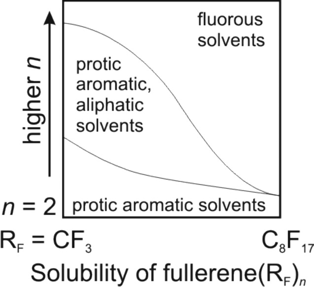
Dependence of PFAF solubility on the type and number of RF groups.
The only quantitative solubility data published was for a series of C60(RF)2 compounds in toluene.104 It was found that 1,7-C60(RF)2 (i.e., para-C60(RF)2) with RF = CF3, C2F5, n-C3F7, i-C3F7, n-C4F9, s-C4F9, and n-C8F17 have solubilities between 1.5 and 8.5 mg/mL (cf. C60, with a toluene solubility of 2.4 mg/mL). In contrast, the compound 1,7-C60(CF2C6F5)2 has a toluene solubility of 400 mg/mL, one of the highest solubilities reported for any fullerene derivative. Such a high solubility can be rationalized by strong interactions between the C6F5 substituents and toluene molecules (In a related phenomenon, it was reported that the solubility of C60 increased in the presence of 1,7-C60(CF2C6F5)2 (see refs (125) and (143) for further information).
The apparent solubility of some TMFs is related in an interesting way to their relative purities.95 Before HPLC separation, some reaction mixtures contain higher concentrations of many of the TMFs in the mixture than the saturation concentration of the purified individual components in the same solvent. This is clearly a kinetic phenomenon. For example, 60-12-1 crystallized extremely slowly from a mixture of other TMFs but did not redissolve in the same amount of solvent. In contrast, an HPLC fraction containing only 60-12-1 formed single crystals more quickly even though it was more dilute.
Many TMFs have high thermal stabilities, and melt or sublime without decomposition. For example, a mixture of C60(CF3)8−10 derivatives melted without decomposition at 400 °C and of a mixture of C60(C2F5)8−10 derivatives melted without decomposition at 290 °C.95 However, the compound 60-12-1 melted at 500 °C with partial decomposition.140 It is not surprising that the sublimation temperatures of fullerene(CF3)n species decrease as the n increases. This is because CF3 and other RF substituents separate the fullerene cages from one another in the solid state, reducing the attractive cage–cage interactions. For example, C60 sublimes at ca. 500 °C under vacuum and 60-10-3 sublimes at ca. 250 °C (under vacuum even though the molar mass of 60-10-3 is nearly twice that of C60).101 Another example is that the enthalpies of sublimation of C60 and 60-12-1 were found to be 175 and 140 kJ·mol−1, respectively.144 The decrease in sublimation temperature or enthalpy of sublimation as n increases was also observed for fluorinated fullerenes.145 Finally, it has been observed that PFAFs derived from HHFs or EMFs have higher sublimation temperatures than those derived from C60 and C70.
Some TMFs are not stable indefinitely at high temperatures, even at the temperature used for their synthesis. Several reports showed that PFAFs with RF = CF3 and C2F5 lose RF groups above 280–350 °C.71,77,79,92 The thermal stability of PFAFs with RF groups larger than C2F5 has not been investigated, but is likely to be even lower. It is also notable that heavier RF groups themselves undergo cleavage at higher temperatures, e.g., C2F5I cleaves to give CF3• radicals (and corresponding mixed C60(C2F5)n(CF3)m).95
3.1. Separation of PFAFs
Perfluoroalkylated fullerenes are typically prepared as mixtures of multiple isomers and multiple compositions. In a few cases, higher synthetic selectivity has been realized, but even in these cases a chromatographic separation was necessary to obtain 98+% pure PFAFs (for example, see the synthesis of 70-10-1 (T1#39,72)68,99 and a synthesis of the series of compounds 60-2-1 RF (T1#111,114)101,104). Except for a few early reports that used flash chromatography and gel permeation chromatography (T1#7,9,1710,14,17), reverse-phase HPLC using specialized columns designed and optimized for fullerene separation has been employed. The most commonly used column is Cosmosil BuckyPrep, although in several publications other HPLC columns were used in conjunction with it to achieve an even better separation (e.g., Cosmosil 5PYE and Regis BuckyClutcher). Several aromatic and aliphatic solvents and their mixtures have been used as eluents. It is constructive to compare eluents used for PFAF separation in terms of how “strong” or “weak” they are. In other words, eluents that interact strongly with the stationary phase of the HPLC column (“strong” eluents) will lead to shorter retention times and lower peak resolution. Eluents that interact weakly with the stationary phase will lead to longer retention times and higher peak resolution. Chlorobenzene is a strongest eluent that has been used for PFAF separation, with toluene being somewhat weaker. Aliphatic hydrocarbons (e.g., hexane and heptane) are much weaker solvents compared to aromatics hydrocarbons, and it has been common practice to use mixtures of toluene and hexane (or heptane) to achieve good separation in a reasonable amount of time (solubility issues notwithstanding, the use of 100% hexane or heptane would lead to prohibitively long retention times for many PFAFs). Recently, mixtures of toluene and polar solvents like acetonitrile and 2-propanol (80/20 or 70/30 v/v) were reported to give good results for the separation of some C60(RF)2 compounds (see T1#105).
The retention times of PFAFs correlate with the number and size of the RF groups. As more RF groups are added to a fullerene cage, or as the RF groups become larger, retention times become shorter. There are very few exceptions to this rule, T1#65,6661,62 and T1#109125). Therefore, as the number of RF groups or their size increases, the separation of PFAFs becomes progressively more difficult.
A typical PFAF HPLC separation is carried out in several stages. The first stage uses a strong eluent typically toluene, and fractions corresponding to mixtures of PFAFs with similar retention times are collected. These fractions are then evaporated to dryness, redissolved in a weaker eluent, then another separation stage. The use of multiple stages allows one to optimize separation times without sacrificing the purity of the isolated PFAFs.
4. X-ray Crystallography and 19F NMR Spectroscopy of PFAFs
4.1. C60(RF)n Derivatives
The development of efficient synthetic procedures for C60 PFAFs, and the surprisingly facile formation of suitably sized crystals resulted in the determination of many dozens of C60(RF)n crystal structures (n = 2−18). Slow solvent evaporation and solvent diffusion are the most common techniques used for growing C60(RF)n crystals. Synchrotron radiation sources have often been employed for X-ray data collection because (i) crystals with dimensions in the range of 10−80 μm, and (ii) with the exception of EMF(RF)n derivatives, PFAFs only contain low-Z atoms with small X-ray scattering factors, namely C, F, and occasionally N and O.
Crystallographic studies of PFAFs have been used for three main purposes: (i) determination of their addition patterns, (ii) prediction of the most likely addition sites for further functionalization, and (iii) validation of theoretical calculations.
4.1.1. Determination of C60(RF)n Addition Patterns
Determination of the X-ray structures for various isomers and compositions of C60(RF)n derivatives was very important at the early stages of PFAF research. Early on, there was controversy about addition patterns deduced from the analysis of 19F NMR spectra: on the one hand, C60(CF3)n addition patterns were believed to be chains of contiguous cage C(sp3) atoms bearing the CF3 groups, similar to the types of addition patterns observed for fluorofullerenes.25,26,35 On the other hand, we proposed that CF3 groups added to fullerenes at the para positions of cage hexagons, and these hexagons were linked so that the intervening hexagons were either para-C6(CF3)2 or meta-C6(CF3)2 moieties.27 This controversy was ultimately resolved in 2005 when we published the first X-ray structure of a PFAF, 60-10-3 (see Table 2 for the IUPAC locants of C60(RF)n isomers).4 The 10 CF3 groups formed five p-C6(CF3)2 hexagons, which were linked by three intervening m-C6(CF3)2 hexagons and one p-C6(CF3)2 hexagon to form a para-meta-para-para-para-meta-para-meta-para ribbon of linked hexagons, which is abbreviated pmp3mpmp.
Numerous X-ray structures that followed revealed that the most common addition patterns of C60(CF3)n compounds could be described as ribbons or loops of edge-sharing m- and/or p-C6(CF3)2 hexagons (each shared edge is a fullerene C(sp3)–C(sp2) bond); occasionally the addition pattern consisted of a ribbon of n − 2 CF3 groups plus an isolated para-C6(CF3)2 hexagon. For example, the addition patterns of 60-4-1, 60-4-2, and 60-4-3 are abbreviated pmp, p,p (i.e., two isolated p-C6(CF3)2 hexagons) and p3 (in some earlier papers the isomer 60-4-3 was referred to as 60-4-2). There is only one possible pmp isomer and one possible p3 isomer for the composition C60(CF3)4; there are 14 possible ways to arrange two isolated p-C6(CF3)2 hexagons on C60, but so far only one such isomer, 60-4-2, is known. Other examples are 60-6-1 (p3mp), 60-6-6 (pmp,p), 60-6-7 (pmpmp), 60-8-1 (p3mpmp), and 60-10-1 (p3mpmp,p). For n ≤ 10, only one compound, 60-10-3, has more than one CF3 group per pentagon (C60 and all other fullerenes have exactly 12 pentagons), almost certainly for steric reasons (CF3 groups are sterically more demanding than Br atoms), and only rarely do CF3 groups occupy adjacent (i.e., ortho) cage C atoms. For n ≤ 12, the only examples are 60-6-2 and 60-12-3. For n ≥ 14, the addition of CF3 groups to adjacent cage C atoms is more common (e.g., 60-14-3, 60-16-2, and 60-16-3). In contrast, X-ray crystallographic studies of the C60 derivatives with bulkier i-C3F7 groups showed that they form only isolated p-C6(i-C3F7)2 hexagons, not ribbons or loops (e.g., 60-6-5-i-C3F7, 60-6-8-i-C3F7, and 60-8-11-i-C3F7). At the same time, less sterically demanding C2F5 groups were found to form the same addition patterns observed for both C60(CF3)n and C60(i-C3F7)n compounds. For example, 60-8-1-C2F5, 60-8-3-C2F5, and 60-10-6-C2F5 have the same addition patterns as their C60(CF3)n counterparts. Formation of these isomers as abundant products demonstrates that the steric strain introduced in these structures due to the larger size of C2F5 groups than CF3 does not affect significantly distribution of the most favorable addition patterns; even additions of C2F5 groups in meta positions appear in these structures. At the same time, C2F5 groups also demonstrate the tendency known for bulky i-C3F7 radicals. For example, the addition pattern of 60-6-8-C2F5 compound is analogous to that of 60-6-8-i-C3F7, in which each pair of RF groups attach to the isolated hexagon in para position. More details about PFAF addition patterns are discussed in section 5.
The combination of X-ray structures and 1D 19F and 2D 19F−19F-COSY NMR spectra of C60(CF3)n isomers (and other fullerene(CF3)n compounds) allowed us to establish a correlation between the conformation of a particular CF3 group and its 19F chemical shift. It was found that CF3 groups that have eclipsed or nearly eclipsed conformations with respect to the three cage C–C bonds that radiate from the C atom to which the CF3 group is attached have −δ values lower than 60 ppm (this was observed in the 19F NMR spectra of 60-10-3, 70-10-1, and 60-12-2). Figure 5 shows this effect for the CF3 group attached to C70 cage atom C4 in the pmp7 ribbon isomer of C70(CF3)10 (70-10-1).
Figure 5.

X-ray structure of the pmp7 isomer of C70(CF3)10 (70-10-1, ref (32)), its 2D COSY 19F NMR spectrum (ref (4)), fragments of the structure showing four p-C6(CF3)2 hexagons, and two Schlegel diagrams indicating the placement and IUPAC locants of the ten CF3 groups and their 19F NMR multiplet assignments. The CF3 group attached to C4 on the C70 cage is nearly eclipsed, and as a consequence its NMR multiplet −δ value is less than 60 ppm. The NMR multiplets for the terminal CF3 groups, attached to C25 and C49, have different 7JFF values as a consequence of different F···F distances and F−C···C−F torsion angles. The shorter F···F distance (2.569(9) Å) and larger F−C···C−F angle (78°) for the CF3 group on C49 resulted in a larger through-space Fermi-contact JFF coupling constant for quartet i (15.9 Hz) than for the CF3 group on C25 (2.744(9) Å, 24°, and 10.3 Hz for quartet j).
In TMFs, 6,7JFF spin−spin coupling values are only observed between CF3 groups sharing the same hexagon or pentagon, because the coupling is almost exclusively mediated by through-space Fermi-contact overlap of F atom lone pairs (see refs (4), (32), (50), and references therein). In all but one case,39 the rapid rotation of CF3 groups about their Ccage–CF3 bond leads to fast-exchange 19F NMR spectra, even at low temperature, and time-averaged 6,7JFF values of 8–20 Hz are typically observed. These give rise to quartets for CF3 groups with only one CF3 group neighbor on a shared hexagon (i.e., CF3 groups on isolated p-C6(CF3)2 hexagons or at the terminus of a ribbon) and quartets-of-quartets (sometimes manifested as apparent septets) for CF3 groups in the interior of a ribbon. This is also shown for 70-10-1 in Figure 5.
Furthermore, Figure 5 demonstrates that the through-space Fermi-contact JFF values depend on the F···F distances and F–C···C–F torsion angles for the F atoms on hexagon-sharing CF3 groups that face one another across the shared hexagon. These structural parameters can be determined by X-ray crystallography with the caveat that the exact conformations of the CF3 groups may be different in the solid state and in solution. Nevertheless, it was observed that shorter distances and/or larger torsion angles invariably lead to larger through-space JFF values.4,31 For example, the 7JFF values for the terminal CF3 groups in 70-10-1 are 15.9 and 10.3 Hz, respectively,4 and the corresponding {F···F distance, F–C···C–F angle} for these CF3 groups are {2.569(9) Å; 78°) and {2.744(9), 24°}, respectively.32
The hypothesis that the observed 6,7JFF values are due almost exclusively to through-space Fermi-contact coupling together with the rapid rotation of TMF CF3 groups led to the conclusion that the “instantaneous” coupling constants for a specific pair of F atoms, one on each of the two neighboring CF3 groups in question, are nine times larger than the 8–20 Hz time-averaged values.4 Consider the pair of proximal F atoms F793 and F801 in the structure of 70-10-1 shown in Figure 5. Rapid rotation of their respective CF3 groups (i.e., rapid on the NMR timescale) would put them 4–5 Å apart 89% of the time (i.e., for eight of the nine possible energy-indistinguishable CF3 rotamers). The through-space coupling constant for these eight rotamers would be essentially 0 Hz. Therefore, the instantaneous 7JFF value for F793 and F801 in the pair of rotamers shown in Figure 5 was tentatively predicted to be 143 Hz. This conclusion was experimentally verified for compounds with p-C6(i-C3F7)2 hexagons, as shown in Figure 6.60,94 Only one of the nine possible rotamers is populated in solution (the DFT-predicted relative energies of rotamers for 60-2-1-i-C3F7 with F···F, F···CF3, and CF3···CF3 contacts above the shared hexagon are 0, 22, and 46 kJ·mol−1, respectively). The observed 7J(FaFb) values of 172 and 160 Hz for 60-4-4-i-C3F7 and 60-6-5-i-C3F7, respectively, verified the “instantaneous 6,7JFF = 9 × observed 6,7JFF” hypothesis. Note that the coupling between either Fa or Fb and the CF3 moieties on the same i-C3F7 groups are < 1 Hz, a likely consequence of offsetting negative through-bond and positive through-space 3JFF coupling-constant components
Figure 6.

X-ray structures of C2-C60(i-C3F7)4 (60-4-4-i-C3F7; ref (94)) and C3-C60(i-C3F7)6 (60-6-5-i-C3F7; ref (60)), fragments of the structures showing p-C6(i-C3F7)2 hexagons, and portions of their 19F NMR spectra showing the ab quartets (i.e., the doublets for Fa and Fb). The observed JFF values of 160 and 172 Hz for proximal fluorine atoms Fa and Fb in these compounds, which are the largest ever recorded for through-space Fermi-contact spin-spin coupling between F atoms attached to C(sp3) atoms and separated by five or more bonds, support the hypothesis that the instantaneous 6,7JFF values for fullerene(CF3)n derivatives are nine times the observed, time-averaged 6,7JFF values of 8–20 Hz.
The analysis of additional X-ray structures and 1D and 2D 19F NMR spectra for TMFs resulted in the determination of common patterns and correlations. DFT predictions of the ribbon isomers for a given composition up to 20 kJ·mol−1 higher in relative energy than the most stable isomer (generally a few dozen isomers) almost always included the observed ribbon isomers (in one of the few exceptions, the observed isomer 60-12-2 was predicted to have a relative energy 40 kJ·mol−1 higher than 60-12-1, the most stable isomer). These insights were useful for tentatively assigning addition patterns for new fullerene(CF3)n compounds, in the absence of crystallographic data. In several cases, addition-pattern predictions based on 19F NMR spectra and DFT calculations were later confirmed by X-ray crystallography. However, there were a few unusual TMF addition patterns that could not be assigned by NMR spectroscopy and DFT calculations and required X-ray crystallography to determine their structures. The first example we encountered was the (p3m2)2-loop isomer of C60(CF3)10 (60-10-4).43a
Determining the addition-patterns of PFAFs with RF groups other than CF3 in the absence of an X-ray structure was always problematic because their 19F NMR spectra are much more complicated. For example, the CF2 moieties in 7,24-C70(C2F5)2 (70-2-1-C2F5) exhibit a significantly second-order 19F NMR abcd spin system with more than 40 individual resonances, presumably due to four time-averaged rotamers with DFT relative energies within 4 kJ·mol−1 of one another.116 Therefore, the growth of single crystals suitable for X-ray crystallography was necessary to accurately determine their addition patterns, and this required highly-purified compounds. This presented an additional problem, because C60(C2F5)n product mixtures with n ≥ 12 and C60(RF)n product mixtures with RF = n-C3F7, n-C4F9, or n-C6F13 were found to be practically inseparable using HPLC procedures.95 Finally, even when X-ray diffraction data were collected, solution and refinement of the structures was hampered by rotational disorder of perfluoroalkyl chains and or the PFAF itself. In several cases, three conformations of RF groups generated by rotation of perfluoroalkyl C–C bonds had to be included in the final refined model.
4.1.2. Single and Double Bonds in C60(CF3)n Derivatives and Validation of DFT Calculations
The relative stabilities of various fullerene(RF)n isomers are determined by at least four factors: (i) the degree of delocalization/aromatization of the remaining π bonds, (ii) the presence or absence of double bonds in the pentagons, (iii) steric repulsion between the RF substituents, and (iv) the rotational conformations of each RF group with respect to the three cage C–C bonds that radiate from the cage C atom to which each RF group is attached. Thus, to understand the relative stability and chemical reactivity of a PFAF with a particular addition pattern, one has to analyze the cage C(sp2)–C(sp2) bonds with respect to their “single” and “double” bond character, and the most straightforward way to do that is to compare the X-ray diffraction derived C–C distances. In favorable cases, the precision of PFAF X-ray structures (i.e., the standard error for individual cage C–C bonds) allows one to determine statistically significant variations in C–C distances. Furthermore, sufficiently-precise X-ray structures allow a particular computational method to be validated as far as accurately predicting C−C distances in the absence of an X-ray structure (assuming that the addition pattern can be discerned from spectroscopic data) or when an X-ray structure clearly shows the addition pattern but has relatively low precision. For visualization of such validations, it is convenient to plot DFT-calculated cage C−C bond distances vs X-ray derived distances. Figure 7 shows the plot for the p3mpmpmp isomer of C60(CF3)10 (60-10-2). This particular isomer is a good example for comparison because it is asymmetric, thereby providing a comparison of the 90 unique cage C–C distances. In this case the standard errors (σ) for individual C–C distances range from ±0.0014 to ±0.0016 Å).43b The experimental and calculated C–C distances are in excellent agreement with each other; the largest difference is less than 6σ, and most of the differences are within 3σ, which validated the particular DFT methodology used in that study.43b
Figure 7.

Correlation between X-ray determined and DFT-predicted cage C–C distances for 60-10-2. The uncertainties shown for the X-ray distances are ±3σ. A drawing of the X-ray structure with 50% probability ellipsoids and the corresponding Schlegel diagram are also shown.
The addition of CF3 groups to a fullerene (or any other substituents for that matter) decreases the number of the C–C double bonds on a fullerene cage. For instance, addition of 10 CF3 groups to C60 fullerene decreases the number of double bonds from 30 to 25. Figure 8 shows that the 25 short cage C–C distances in 60-10-2 vary from 1.354(2) to 1.402(2) Å. The other C–C distances range from 1.422(2) to 1.552(2) Å. In the X-ray structure of C60·Pt(OEP)·2C6H6, the 30 “double bonds” and 60 “single bonds” in the underivatized C60 cage span relatively narrow ranges, 1.379(3)–1.391(3) and 1.440(3)–1.461(3) Å, respectively. Therefore, the C(sp2)–C(sp2) bonds in C60(CF3)n can be assigned as “single bonds” or “double bonds” only as a first approximation. Nevertheless, the shortest ones presumably have the most double-bond character and can be considered the most probable reactive sites for further derivatization. For example, the stucture of 60-4-3 structure revealed the presence of the very short (1.347 Å) double bond in the fulvene-like moiety, as shown in Figure 9. This is the most reactive bond as demonstrated by the rapid epoxidation of 60-4-3 in air to C60(CF3)4O,113 the structure of which is also shown in Figure 9. The analogous compound C60(C2F5)4O is probably formed by a similar epoxidation of the fulvene-like double bond in the putative intermediate 60-4-3-C2F5.39 Interestingly, an epoxide was not formed by exposure of the isomer of C60(CF3)2(i-C3F7)2 with the 60-4-3 addition pattern (the i-C3F7 groups are the terminal RF substituents in the p3 ribbon), probably because the bulky i-C3F7 groups shield the reactive double bond, as also shown in Figure 9.95 More recently, an epoxide of C60(CF3)6 has been isolated and structurally characterized.105 The O atom in this compound occupies the same position on the cage as in the C60(RF)4O epoxides.
Figure 8.

X-ray diffraction determined cage C–C bond distances for C60 and the p3mpmpmp isomer of C60(CF3)10 (60-10-2) (the uncertainties shown are ±3σ). Note the breaks between sets of C(sp2)–C(sp2) “double bonds” (i.e., those bonds with significant double-bond character), C(sp2)–C(sp2) “single bonds”, and, for 60-10-2, the 30 C(sp2)–C(sp3) single bonds. The C60 distances are from CCDC CIF file 198536 (see also doi 10.1039/B306714A).
Figure 9.

X-ray structures of p3-C60(CF3)4 (60-4-3), C60(CF3)4O, C60(C2F5)4O, and C60(CF3)2(i-C3F7)2 (from left to right). The red bond is the shortest and most reactive double bond in the fulvene-like fragments of the two PFAFs.
4.2. X-ray Crystallographic Studies of C70(RF)n Derivatives
There are many dozens of structures in the family of C70(RF)n compounds that have been determined by X-ray crystallography. The pool of the known C70(RF)n addition patterns is more diverse compared with C60(RF)n structures due to the existence of many C70(RF)n compounds with n-C3F7 groups. HPLC purification of PFAFs of fullerenes with cages larger than C60 is easier to achieve because larger fullerenes and their derivatives have longer retention times than their C60 counterparts. This has resulted in a larger number of sufficiently purified and crystallized PFAF isomers for C70 than for C60. Some structural trends observed for C60(RF)n compounds are also valid for C70(RF)n derivatives. For example, some RF groups (RF = CF3, C2F5, and n-C3F7) form ribbons and loops on the C70 cage. Table 3 shows that identical addition patterns have been observed for a number of CF3 and C2F5 compositions, such as 70-10-1 and 70-10-1-C2F5 and 70-8-1-C2F5. Moreover, four structurally characterized minor isomers of C70(n-C3F7)8 have the same addition patterns as 70-8-3-C2F5, 70-8-4-C2F5, 70-8-5-C2F5, and 70-8-6-C2F5. Remarkably, the 70-8-4 addition pattern is the same for RF = CF3, C2F5, and n-C3F7. Thus, the size of the n-C3F7 group does not prevent formation of ribbon isomers observed for the smaller CF3 and C2F5 substituents. However, i-C3F7 groups only form isolated p-C6(i-C3F7)2 hexagons on both C60 and C70 cage. The other important structural principle that was found for C70(RF)n derivatives with n ≤ 20 and for HHF(RF)n derivatives in general57,70 is that the RF groups are rarely attached to triple-hexagon junctions because these are the least pyramidalized cage C(sp2) atoms. Additions to fullerenes are promoted by the pyramidalization of cage C(sp2) atoms when they accept an exohedral substituent and become cage C(sp3) atoms, and therefore, other things being equal, the most pyramidalized (i.e., most strained) cage C(sp2) atoms in a fullerene or fullerene derivative are the preferred sites for additions. Only a few violations of this principle are known and are discussed in detail in section 5.4.84a,90
As discussed earlier, the addition patterns for many C70(CF3)n derivatives can be elucidated by a combination of 19F NMR spectroscopy and DFT calculations.38,68 However, for RF groups other than CF3, , X-ray crystallography is still the only reliable way to obtain information about RF group locations. The relative ease of growing single crystals from solutions of HPLC-purified C70(C2F5)n isomers enabled the structure determination of several compounds. However, unlike C60(C2F5)n derivatives in which all major isomers were isolated and structurally characterized,40,54 the most abundant isomers in C70(C2F5)n product mixtures have not yet been isolated with high purity.77,95 Thus, it is premature to generalize trends for the addition patterns and structural features of C70(C2F5)n derivatives. It is not even known how many isomers of some C70(C2F5)n compositions are present in some reaction product mixtures. Further progress in this direction will depend on the new breakthroughs in separation methods.
As in the case of C60(RF)n derivatives, structural information obtained from X-ray crystallography was used to predict the most reactive sites for further functionalization. For example, analysis of the X-ray structure of 70-10-1 (Figure 10) showed that cage C–C distances vary from 1.347(3) to 1.562(3) Å. The C33–C34 bond is the shortest non-terminal double bond in that compound (1.386(3) Å). This bond connects two unoccupied pentagons (the other 10 pentagons each have one CF3 group), and it was predicted to be the most reactive site for cycloadditions. Structural characterizations of the C70(CF3)10(C(CO2Et)2) and C70(CF3)10C2H4(C6H2(MeO)2) cycloadducts (see Figure 10) verifed the high reactivity of that particular bond.76,99,146
Figure 10.

X-ray structures of 70-10-1 (middle), C70(CF3)10(C(CO2Et)2) (right), and C70(CF3)10C2H4(C6H2(MeO)2) (left). The reactions that formed the cycloadducts are also shown.
5. PFAF Addition Patterns
5.1. Additions to C60
The C60 molecule has two types of C–C bonds, hexagon/hexagon (hex/hex) edges and pentagon/hexagon (pent/hex) edges, with bond distances of ca. 1.40 and 1.45 Å, respectively, and, as previously discussed, can be thought of as double and single bonds, respectively (see Figure 8. In this section, we will only consider the addition of substituents X that form single bonds to a cage C atom, converting its hybridization from predominantly sp2 to sp3. There are 23 possible isomers of C60X2, 4,190 possible isomers of C60X4, 418,470 possible isomers of C60X6, etc.147 The numbers of isomers for n ≥ 10 is in the millions or, for higher fullerenes, in the billions. It was therefore desirable to find guiding principles that would allow one to limit the number of plausible isomers to consider, and this problem was addressed in a number of computational studies. If a reaction proceeds under thermodynamic control (i.e., if an equilibrium or close-to-equilibrium distribution of isomers of a given composition is expected), the DFT relative energies of the isomers may be used to predict the most abundant products. On the other hand, kinetic factors can be even more important than the isomers’ relative thermodynamic stability in some cases, and theoretical predictions of the products may be severely complicated by the fact that the thermodynamic or kinetic control of the reaction is not easily known. As discussed in section 2, perfluoroalkyl additions to fullerenes are usually performed at high temperatures when rearrangements of the RF groups on the fullerene surface appear to be possible, and hence the thermodynamic stability of the isomers should determine, in large part, their relative abundance in the product mixture. Therefore, in this section we will analyze the factors affecting thermodynamic stability of fullerene(RF)n isomers and discuss the lowest energy addition pattern trends. However, kinetic factors cannot be fully ignored, and their role will be discussed in section 5.1.4.
5.1.1. 1,2 (ortho) and 1,4 (para) Addition and Double Bonds in Pentagons
Computational studies of C60X2 isomers (X = H, F, Cl, Br, CH3, and t-C4H9) performed at semiempirical and DFT levels of theory since the early 1990s showed that only two isomers should be considered for small and medium-size groups.148 One of these two addition motifs is when the two X groups are added to a hex/hex double bond of C60, forming two edge-sharing o-C6X2 hexagons (the shared edge is the cage C(sp3)C(sp3) bond), as shown in Figure 11a. In this case, the rest of the fullerene π-system remains unchanged. The other common addition motif for C60X2 derivatives results in the formation of a p-C6X2 hexagon, and in this case, the remaining π-system is adjusted by relocating one double bond to a pentagon/hexagon edge (i.e., one double bond in a pentagon (DBIP) is formed), as shown in Figure 11b). All other C60X2 addition patterns require more pronounced changes in the fullerene π-system and result in a larger number of DBIPs.
Figure 11.

(a) A fragment of a 1,9-C60X2 derivative showing the 1,2 or ortho addition motif; (b) a fragment of a 1,7-C60X2 derivative showing the 1,4 or para addition motif; (c) p3-C60X4; (d) pmp-C60X4. In (c) and (d), the meta- and/or para-C6X2 hexagons (p or m, respectively) are highlighted in yellow.
The number of DBIPs was found to be an important relative-energy predictor: more DBIPs results in a higher relative energy (i.e., a lower thermodynamic stability).148a At the semiempirical AM1 and PM3 levels, the penalty for each DBIP in C60X2 isomers was estimated to be 36–39 kJ·mol−1 (for X = H, F, and t-C4H9).148 Accordingly, 1,9-C60X2 isomers should be thermodynamically favored for small substituents such as H and F,148b,149 in good agreement with the experimental structures 1,9-C60H2149 and 1,9-C60F2.150 However, the ortho position of the X groups in 1,9-C60X2 inevitably leads to an eclipsed conformation and hence a repulsive interaction (i.e., the X–C–C–X torsion angle is 0°). With the increase of the size of the groups, the repulsion is increasing and can balance the destabilizing effect of DBIP. Not surprisingly, computational studies show that for bulky substituents the 1,7-C60X2 isomer is more stable.27,126,148b For example, PBE/TZ2P DFT calculations showed that the 1,7-C60X2 isomer is more stable than 1,9-C60X2 by 14 kJ·mol−1 for X = Br and by 35 kJ·mol−1 for X = CF3.151 Note that the different energy differences between the X = Br and the X = CF3 isomers is consistent with the fact that CF3 is sterically larger than a Br atom. In summary, the studies of C60X2 show that the products of multiple additions of X groups are determined by at least two factors: (i) destabilizing double bonds in pentagons and (ii) destabilizing eclipsing interactions of bulky groups. For bulky groups, such as CF3, multiple “1,4”-additions are to be expected.
5.1.2. Multiple Additions of Bulky Groups to C60: General Principles
Important principles of multiple additions of bulky groups to C60 were formulated in the 1990s by Clare and Kepert, who performed extended semiempirical (AM1) computational studies of C60Xn isomers. In brief, the methodology of the authors included a search of the most stable isomers of C60Xn, sorting out a majority of the unstable structures, and then a search of the most stable isomers of C60Xn+2 based on several most stable isomers of C60Xn. A gradual increase of n allowed Clare and Kepert to cover a broad range of compositions, reveal some general principles of the multiple addition to C60 and other fullerenes, and predict several addition patterns, which were indeed found later in the experimental studies. Although the authors did not study CF3 additions (their work was done before intense studies of fullerene perfluoroalkylation were started in the early 2000s), their results on the addition of Br atoms to C60 are relevant for CF3 addition as well and will be briefly discussed here.
Clare and Kepert showed that para addition of two Br atoms to C60 is energetically more preferable than ortho addition by 5.1 kJ·mol−1 at the AM1 level. However, the energy difference is not large and the possible formation of 1,9-C60Br2 due to kinetic control should not be ruled out. The AM1 study of C60Br4 isomers showed that the two lowest energy isomers resulted from consecutive para additions while the third most stable isomer was the result of one ortho addition and one para addition.152 Regression analysis of the relative energies of C60Br4 isomers as a function of the number of C6Br, C60Br, C6Br2, C60Br3, etc. hexagons revealed that the most stable bromofullerene isomers have ribbons of edge-sharing m- and/or p-C6Br2 hexagons rather than isolated p-C6Br2 hexagons or o-C6Br2 hexagons (i.e., the addition of pairs of bromine atoms to distant parts of C60). For instance, Figure 11 shows that the most stable isomer of C60Br4 has the 60-4-3p3 addition pattern, the second most stable isomer has the 60-4-1pmp addition pattern, and the third most stable isomer has an omp addition pattern, which is not observed for any fullerene(RF)4 derivative but which is a fragment of the skew-pentagonal pyramid (SPP) addition pattern of 60-6-2 shown as a Schlegel diagram in Figure 12. The SPP addition pattern is a p5 loop of five X groups with the sixth substituent inside the loop, ortho to one of the other X groups and meta to two others.
Figure 12.

Schlegel diagrams of C60(RF)x derivatives. Color codes: meta- or para-C6X2 hexagons are highlighted in yellow, “m” denotes meta-C6X2 hexagons; 1,3,5-C6X3 hexagons are highlighted in green; pentagon with two RF groups are highlighted in blue; positions of attached RF groups are denoted as black circles; RF groups attached to adjacent carbon atoms are light blue circles with a black border; non-terminal double bonds in pentagons (nt-DBIP) are marked red.
Further addition of Br atoms to the p3 or omp isomers of C60Br4 resulted in the prediction152 that the SPP addition pattern is the most stable for C60Br6, in harmony with the observed structure of C60Br6153 and one of the known isomers of C60(CF3)6.39 The second most stable isomer of C60Br6 predicted in Clare and Kepert’s study had the p3mp ribbon exhibited by the most stable isomer of C60(CF3)6. The next two added Br atoms continue the tendency of the string formation: at the AM1 level, the most stable isomer of C60Br8 had a p3mpmp string. For C60Br12, the authors predicted that two of the most stable isomers have an addition pattern with two SPP fragments on opposite sides of C60 and a (pm)6-loop (cf. the structures of 60-12-3 and 60-12-1 in Figure 12, which are known to have these addition patterns.5,36,52 For further addition of Br atoms, the competition between SPP fragments and ribbons continues up to C60Br18, for which the isomer with three SPP fragments is predicted to be the most stable. Finally, Clare and Kepert predicted that the most stable structure for C60Br24 has Th symmetry and no cage C(sp3)–C(sp3) bonds (24 is the largest number of substituents for which such a restriction is possible).152,154 This isomer corresponds to the experimentally observed structure of C60Br24.155 In summary, the seminal computational studies of Clare and Kepert revealed important trends for the addition of Br atom to C60, which later proved to be relevant for the prediction of CF3 additions to fullerenes. Based on their work, and the similarity in size of a Br atom and a CF3 group, a significant percentage of the most-stable fullerene(CF3)n isomers were expected to have either one or more ribbons of edge-sharing m- and p-C6(CF3)2 hexagons (with the occasional isolated p-C6(CF3)2 hexagon), SPP fragments (even though they contain o-C6(CF3)2 hexagons, or CF3 groups on adjacent cage C atoms), or both.
5.1.3. Addition Patterns of C60(CF3)n, n = 2–18
Clare and Kepert's work, described above, coupled with the large number of well-characterized PFAFs described in this Review, including over 100 TMFs, justified exhaustive independent theoretical/experimental studies of fullerene(CF3)n compositions/isomers, and these were carried out by Olga Boltalina's former group at Moscow State University (see the papers containing theoretical results co-authored by Alexey Goryunkov and/or Ilya Ioffe, among others) and by Boltalina's current group at Colorado State University and their collaborators (see the papers containing theoretical results co-authored by Alexey Popov at the IFW Dresden; with two exceptions, all of this computational work was performed by Popov at IFW Dresden). Significant progress in computing hardware and software since Clare and Kepert's AM1 studies allowed thousands or tens of thousands of addition patterns to be screened for their relative energies, first at the AM1 level of theory and then, for the ca. 100 most-stable AM1 isomers, by DFT calculations. The isolation of multiple isomers of most C60(CF3)n compositions for every even n value from 2 to 18 enabled a more detailed comparison of experimental structures and theoretical predictions (see Table 2 for a list of structurally characterized C60(RF)n compounds and Figure 12 for their Schlegel diagrams). In this section, we discuss the guidelines of CF3 addition to C60 revealed in computational studies and then analyze experimentally elucidated CF3 addition patterns in this context. If not otherwise specified, the relative energies are computed at the PBE/TZ2P level (hereafter designated simply as DFT). The relative energies either are taken from the cited publications or are unpublished results of the authors. In some cases the relative energy of a particular isomer reported by different groups varied by 1–2 kJ·mol−1 because the optimizations terminated with slightly different sets of CF3 rotational conformations.
5.1.3.1. C60(CF3)2
Both AM1 and DFT calculations unambiguously showed that 1,7-C60(CF3)2 is considerably more stable than the 1,9-C60(CF3)2; the DFT relative energy of the latter was found to be 34.7 kJ·mol−1.151 Therefore, “1,2”-additions of CF3 groups are not expected to lead to abundant reaction products. Indeed, the sole experimentally characterized isomer of C60(CF3)2 is p-60-2-1.27,63
5.1.3.2. C60(CF3)4
The DFT-predicted most stable isomers of C60(CF3)4 are p3 (0 kJ·mol−1) and pmp (8.2 kJ·mol−1), similar to the situation described earlier for C60Br4.151 The relative energy of the o,p-C60(CF3)4 isomer is 36.3 kJ·mol−1 (for comparison, the relative energy of o,p-C60Br4 was found to be only 9.9 kJ·mol−1).151 Fourteen p,p-C60(CF3)4 isomers (i.e., structures with two isolated p-C6(CF3)2 hexagons span the relative energy range of 10–34 kJ·mol−1. These data show that, although the p3 and pmp ribbon isomers are more stable than p,p addition patterns, the most stable p,p isomers are reasonable products to expect in high temperature syntheses. Note that two p-C6(CF3)2 hexagons can be combined in such a way that two CF3 groups share the same pentagon. DFT calculations show that the CF3 group is sufficiently bulky to induce considerable steric repulsive interactions in C5(CF3)2 pentagons even when the CF3 groups are not attached to adjacent cage C atoms. The relative energies of two C60(CF3)4 isomers with a 1,3-C5(CF3)2 pentagon are 58 and 62 kJ·mol−1, and the relative energy of the isomer with two C5(CF3)2 pentagon is 84 kJ·mol−1.
Experimental structural studies agree well with these computational results. To date, three isomers of C60(CF3)4 have been structurally characterized. The most abundant isomer has the pmp addition pattern (60-4-1).27,63 Another experimentally observed product characterized structure is the most stable p,p-C60(CF3)4 isomer, 1,7,16,36-C60(CF3)4 (60-4-2).63 The more stable p3-60-4-3 is too reactive and was unambiguously characterized only recently,113 whereas in earlier studies its epoxide C60(CF3)4O was observed.27,39 The p3 addition pattern can be also stabilized by more bulky RF groups, which allowed the authors of refs (80 and 95) to characterize p3-C60(CF3)2(i-C3F7)2.
5.1.3.3. C60(CF3)6
The addition of six CF3 groups to C60 follows the guidelines already revealed for C60(CF3)4. The most stable isomer has a p3mp ribbon of CF3 groups. There are two pmpmp ribbon isomers without a 1,3-C5(CF3)2 pentagon, and their relative energies are 6.5 and 10.2 kJ·mol−1.63,151 The relative energies of the most stable p3,p isomers are only 2–3 kJ·mol−1 above the p3mp isomer,63 whereas the relative energy of the most stable pmp,p isomer is 10 kJ·mol−1 (hereinafter p3,p and pmp,p isomers will be designated 4+2 isomers). Para additions can also lead to p,p,p isomers with three isolated p-C6(CF3)2 hexagons. The most stable isomer of this type is only 6 kJ·mol−1 less stable than p3mp. Finally, the SPP isomer of C60(CF3)6 was predicted to be 14 kJ·mol−1 less stable than p3mp.63,151 Interestingly, this value is substantially smaller than the destabilization effect of 35 kJ·mol−1 computed for the isomer of C60(CF3)2 with two CF3 groups on adjacent cage C atoms. In summary, many isomers of C60(CF3)6 have DFT-predicted relative energies no higher than 14.4 kJ·mol−1 and on this basis might be expected to be found in reaction products containing the composition C60(CF3)6.
Known C60(CF3)6 isomers include p3mp (60-6-1) and one of the two possible pmpmp isomers (60-6-6).27,63 Among the 4+2 isomers, only 60-6-7, which has a pmp,p addition pattern with a relative energy of 16 kJ·mol−1 has been reported.63 Isomers of C60(CF3)6 with p,p,p addition patterns are not known, but have been isolated and characterized for C60(RF)6 with RF = C2F5 and i-C3F7, as discussed below.
The only other known isomer of C60(CF3)6 is SPP-C60(CF3)6 (60-6-2).39,105 It's DFT-predicted relative energy is 14.4 kJ·mol−1 above 60-6-1 and its relative yield in a 550 C hot-tube synthesis was reported to be ca. 20 times lower than 60-6-1.39 If one accounts for the difference in symmetry numbers that favor the C1 isomer 60-6-1 over the Cs isomer 60-6-2, the difference in ΔGf values is 19.1 kJ·mol−1. If the two compounds were in thermal equilibrium at the reaction temperature, then their relative abundances would be 16:1, in reasonable agreement with the observed ca. 20:1 ratio.39
5.1.3.4. C60(CF3)8
From the aforementioned DFT analysis of the addition of 2–6 CF3 groups to C60, one would expect that most of the lowest energy isomers of C60(CF3)n would have ribbon and 6+2 addition patterns (i.e., a ribbon of 6 CF3 groups and an isolated p-C6(CF3)2 hexagon). Indeed, extensive computations showed that the most stable isomer has a p3mp,p addition pattern, and the second most stable isomer (3 kJ·mol−1 less stable) has the one and only p3mpmp addition pattern.5,53 There are only three all-ribbon isomers, p3mpmp and two pmpmpmp addition patterns (both pmpmpmp isomers have relative energies less than 20 kJ·mol−1), but many 6+2 isomers. There is also a pmp,pmp 4+4 double-ribbon isomer with ΔE = 11 kJ·mol−1, and isomers with SPP,p addition patterns, the most stable of which has ΔE = 17 kJ·mol−1). To the extent that experimentally-observed reaction products have reasonably low ΔE values, which is almost always the case for high-temperature syntheses, many isomers of C60(CF3)8 can be expected: there are four with relative energies below 10 kJ·mol−1 and 28 in the range 10–20 kJ·mol−1.
To date there are are two structurally characterized C60(CF3)8 isomers with ribbon addition patterns, 60-8-1 and 60-8-4, and three with p3mp,p addition patterns, 60-8-2, 60-8-3, and 60-8-5, all with 0–11 kJ·mol−1 ΔE values.5,44,53,58 Several isomers that have not been structurally characterized have also been isolated.
5.1.3.5. C60(CF3)10
As would be expected, the number of possible isomers increases with the number of added CF3 groups, and C60(CF3)10 has the richest family of isomers among all fullerene(RF)n compositions. DFT calculations show that all-ribbon isomers, and many 8+2 and 6+4 isomers have ΔE = 0–20 kJ·mol−1 (this includes no fewer than 31 isomers). The four all-ribbon isomers have ΔE ≤ 8 kJ·mol−1, the two most stable have p3mp,pmp and p3mpmpmp addition patterns. The large number of DFT-predicted stable isomers is in harmony with the number of isolated isomers with appreciable yields. There are six structurally-characterized isomers with addition patterns described above, 60-10-1, 60-10-2, 60-10-3, 60-10-5, 60-6-6, and 60-10-7.4,5,43,63 There is also the unusual C2-symmetric (p3m2-loop)2 isomer 60-10-4, with ΔE = 8 kJ·mol−1.43a
5.1.3.6. C60(CF3)12
The situation with 12 CF3 groups on C60 is rather special because one isomer, the S6-symmetic (pm)6-loop isomer predicted by Clare and Kepert (but not known experimentally) for C60Br12, was found to be at least 19 kJ·mol−1 more stable than all others.56 This turns out to be the only single-ribbon addition pattern that avoids putting more than one CF3 group in each of the 12 pentagons. The next three most stable isomers have ΔE = 19–21 kJ·mol−1) and can be described as “branched” ribbons, with the branching occurring at a 1,3,5-C6(CF3)6 hexagon (interestingly, no stable isomer of C60(CF3)10 has a 1,3,5-C6(CF3)6 hexagon). All other types of isomers obtained by consecutive 1,4 additions of CF3 groups have at least one 1,3-C5(CF3)2 pentagon which appears to be quite destabilizing (all have ΔE ≥ 31 kJ·mol−1), which is in sharp contrast to the stability of 60-10-3, which has a 1,3-C5(CF3)2 pentagon and for which ΔE is only 7 kJ·mol−1. Another interesting contrast is the relative stability of the SPP addition pattern for 60-6-2 (14.1 kJ·mol−1) compared with the 33–34 kJ·mol−1 isomers of C60(CF3)12 that have two SPP addition-pattern fragments on opposite poles.56
The list of six experimentally well-characterized isomers of C60(CF3)12 includes the most stable S6-symmetric (pm)6-loop isomers 60-12-1,36 two isomers with branched ribbons but only one CF3 per pentagon, 60-12-5 (C3 symmetry) and 60-12-6,74 the C2h-symmetric isomer with two SPP fragments, 60-12-3,5,52 and two isomers that have two 1,3-C5(CF3)2 pentagons, 60-12-2 and 60-12-4.56,67 The relative energies of 60-12-2 and 60-12-4 are 40 and 46 kJ·mol−1, respectively, so it is quite possible that they are kinetic isomers.
5.1.3.7. C60(CF3)14–18
With more than 12 CF3 groups all addition patterns will have at least two “destabilizing” 1,3-C5(CF3)2 pentagons that may compete in overall stability with addition patterns having some CF3 groups on adjacent cage C atoms. The lowest energy isomer of C60(CF3)14, 60-14-1, is formed by consecutive 1,4 additions, has two 1,3-C5(CF3)2 pentagons, and one 1,3,5-C6(CF3)3 hexagon that forms a branched ribbon.52 However, the lowest energy isomer with an SPP fragment, 60-14-3, is only 0.4 kJ·mol−1 less stable. The third lowest energy isomer, 60-14-2 (ΔE = 2.2 kJ·mol−1), is based on the S6-(pm)6-loop addition pattern of 60-12-1 with two additional CF3 groups forming two 1,3-C5(CF3)2 pentagons. All three are known experimentally.52,74
For C60(CF3)16, which must have even more 1,3-C5(CF3)2 pentagons, SPP and ribbon isomers are equally stable; moreover, it was found that stable addition patterns with CF3 groups on adjacent carbon atoms can be realized without formation of an SPP moiety.55 The isomers are densely distributed in the energy scale: seven isomers with relative energies below 10 kJ·mol−1, eight isomers in the 10–20 kJ·mol−1 range. The three experimentally well-characterized isomers of C60(CF3)16, one has o-C6(CF3)2 hexagon (not as part of an SPP fragment (60-16-3, ΔE = 4 kJ·mol−1)), one has an SPP moiety (60-16-2, ΔE = 10 kJ·mol−1), and one is based on consecutive 1,4-additions but with no CF3 groups on adjacent cage C atoms (60-16-1, ΔE = 16 kJ·mol−1).54 Many experimentally isolated isomers have not yet been structurally characterized, and the most stable C60(CF3)16 isomers are not among the three listed above.
For C60(CF3)18, theoretical studies have shown that the most stable isomer has C3v-symmetry, two isolated benzenoid rings, three isolated fulvene fragments, six isolated double bonds, nine 1,3-C5(CF3)2 pentagons, and no CF3 groups on adjacent cage C atoms.54 The isomer with this addition pattern, 60-18-2, has been isolated and characterized by single-crystal X-ray diffraction.82 It is followed by four isomers with SPP moieties (ΔE = 9–28 kJ·mol−1). Note that these isomers span a larger range of relative energies than TMFs with 8, 10, 14, and 16 CF3 groups. Furthermore, it is impossible to distribute 18 CF3 groups on the surface of C60 without significant steric hindrance, and hence the guidelines formulated for stable addition patterns with fewer CF3 groups are not followed as strictly. In fact, the list of most stable isomers of C60(CF3)18 includes only a few without o-C6(CF3)2 hexagons, and the experimentally characterized 60-18-1 is one of them.55 This isomer is 33 kJ·mol−1 less stable than 60-18-2. Up to now, 18 is the largest number of CF3 groups in structurally characterized C60(CF3)n derivatives.
Calculations show that the energy of CF3 addition to C60(CF3)18 is considerably decreased as compared to previous stages of addition, from which one can conclude that C60(CF3)n derivatives with more than 18 CF3 groups are unlikely to be abundant reaction products.109 For example, the Th-symmetric C60X24 structure, known for X = Br, is unknown for X = CF3.
5.1.4. Thermodynamic versus Kinetic Aspects of CF3 Addition
Analysis of the experimentally available structures of C60(CF3)n derivatives and comparison to the results of exhaustive computational studies show that in many cases the experimentally available isomers are the most stable ones, or at least have low relative energies. Thus, partial thermodynamic control in high-temperature trifluoromethylation of fullerenes can be postulated. Thermodynamic control implies that the isomers with high relative energy can be converted into the products with lower energies, which means that CF3 groups can rearrange on the fullerene surface (or between two neighboring molecules). The fact that such rearrangements are possible was demonstrated by transalkylation reactions, such as the reaction between C60 and C60(CF3)12, which produced products with intermediate numbers of CF3 groups.87,105,111 At the same time, there are a number of isolated derivatives with n ≥ 12 with high relative DFT-predicted energies. The latter fact indicates that complete thermodynamic equilibrium is not always reached.
It is instructive that at low stages of addition (i.e., n ≤ 10), the majority of the most stable isomers of C60(CF3)n+2 can be conceptually formed by addition of two CF3 groups to the most stable isomers of C60(CF3)n without rearrangement. The gradual growth of the thermodynamically most stable ribbon addition patterns from 4 to 10 groups is a clear example: p3 → p3mp→ p3mpmp→ p3mpmpmp, and pmp3mpmp; pmp → pmpmp → pmpmpmp → pmpmpmpmp. Rearrangement of the precursor C60(CF3)n derivative during the addition of the next two CF3 groups is not necessary. Therefore, it is possible that thermodynamically stable isomers can be produced even under partial kinetic control.
However, for n ≥ 12, the most stable isomers of C60(CF3)n+2 are generally not derived from the DFT-predicted most stable C60(CF3)n addition patterns, and their formation would require multiple rearrangements of CF3 groups on the fullerene surface and/or CF3 dissociation/reassociation reactions. Hence, it is more difficult to obtain an equilibrium distribution of products for large n values, and reactions should proceed at higher temperatures, include longer thermal treatments, or both.156 These requirements were not completely fulfilled in many reported syntheses, which is probably why isomers with high relative energies were isolated. For instance, in a hot tube synthesis with flowing CF3I, products with high n values were removed relatively quickly from the hot reaction zone because of their relatively high volatility. As a result, two C60(CF3)12 isomers, 60-12-2 and 60-12-4, with DFT-predicted energies significantly higher than the most stable isomer, were isolated (the latter has the highest energy relative to the most stable isomer, 46 kJ·mol−1, of all well-characterized fullerene(RF)n derivatives). Similarly, the isomer 60-18-1, with a high relative energy, was obtained in the first synthesis of C60(CF3)18 derivatives, and three isolated isomers of C60(CF3)16 are not the most stable. Thus, for n ≥ 12, kinetic and thermodynamic principles favor different isomers, and hence equilibrium compositions are more difficult to achieve.
DFT calculations show that intra- or intermolecular rearrangements of CF3 groups have activation barriers higher than 200 kJ·mol−1.142,157 It was proposed that isomer distributions under non-thermodynamic conditions can be rationalized with the Bell–Evans–Polanyi principle,156 which states that reaction rates correlate with reaction enthalpies for similar reactions. In the case of radical trifluoromethylation, this means then that kinetically preferred C60(CF3)n derivatives should include the most stable C60(CF3)n−1 radicals as intermediates.63,87,156
5.1.5. Addition of Bulky RF Groups to C60
It can be expected that the increase of the perfluoroalkyl group from CF3 to C2F5 and beyond should introduce additional sterical hindrances for C60(RF)n. Although this is correct to some extent, RF groups cannot be considered as hard spheres, and a careful analysis of their shapes and relative orientations was considered.
5.1.5.1. Addition of C2F5
To reiterate some facts presented earlier, (i) each cage C atom in C60 is at the junction of two hexagons and one pentagon, and (ii) CF3 groups attached to C60 preferably adopt staggered conformation (i.e., the three F atoms are located above the hexagons and pentagon rather than above the C–C bonds). Rotation of a CF3 group around the C(fullerene)–C(RF) bond by 120° leaves a structurally and energetically congruent structure. Clearly the situation is different with RF = C2F5, as shown in Figure 13 for 1,7-C60(C2F5)2. Staggered conformations are still more stable than eclipsed conformations, but 120° rotations result in three types of steric interactions above the shared hexagon, F···F, F···CF3, and CF3···CF3. However, if one of the F atoms in the CF3 group is replaced by another CF3 group (which yields C2F5), the staggered conformation remains preferable, but rotation around the C(fullerene)–C(RF) bond yields up to three different conformers. For 1,7-C60(C2F5)2, this conformation variability results in six different conformers, whose energies vary significantly in dependence on the relative orientations of C2F5 groups. The steric repulsion of two C2F5 groups in para position is dominated by interactions of F atoms and/or CF3 fragments located above the hexagon shared by both groups. Hence, there are three possible variants of how C2F5···C2F5 interactions can be realized in C60(C2F5)2 (see Figure 13): F···F contacts (two F atoms above the shared hexagon), F···CF3 (one F atom and one CF3 group), and CF3···CF3 (two CF3 groups above the shared hexagon). The former situation is realized in the three most stable conformers (ΔE = 0–2 kJ·mol−1). Two conformers with F···CF3 contacts are destabilized by ca. 10 kJ·mol−1 (ΔE = 11–12 kJ·mol−1), and the conformer with two CF3 groups over the shared hexagon is the least stable, a the relative energy of 42 kJ·mol−1. It is clear that conformers of 1,7-C60(C2F5)2 with F···F contacts above the shared hexagon do not experience significantly increased steric repulsion relative to 1,7-C60(CF3)2.
Figure 13.

Three DFT-optimized conformers of 1,7-C60(C2F5)2: (a) two F atoms above the shared hexagon; (b) one F atom and one CF3 group above the shared hexagon; (c) two CF3 groups above the shared hexagon (note the eclipsed conformations of the C2F5 groups). The shared hexagon is highlighted in red. Top and bottom rows show different orientations of the conformers.
For the addition of four or more C2F5 groups, one should consider either ribbon addition patterns (p3 or pmp) or isomers with isolated p-C6(C2F5)2 hexagons. Importantly, each RF group in the middle of the ribbon shares at least two hexagons with other RF groups. The preference of ribbon isomers for C60(CF3)n derivatives means that F···F contacts over shared hexagons do not introduce strong repulsive interactions (note, however, that there are examples of eclipsed conformations for one of the CF3 groups in 1,3-C5(CF3)2 pentagons or 1,3,5-C6(CF3)3 hexagons, showing that such F···F interactions are not negligible). Ribbon addition patterns are possible for C2F5 groups because the two α-F atoms of the non-terminal C2F5 groups can share both p-C6(C2F5)2 hexagons in the ribbon (i.e., without any destabilizing F···CF3 and CF3···CF3 contacts over the shared hexagons; note that this puts the CF3 moieties of the non-terminal C2F5 groups over pentagons). Indeed, the DFT results listed in Table 4 show that the p3 isomer of C60(C2F5)4 is more stable than any of the possible p,p isomers. Nevertheless, the energetic preference for fullerene(C2F5)n ribbon isomers is less emphasized than for fullerene(CF3)n ribbon isomers. For example, the pmp-C60(C2F5)4 is a few kJ·mol−1 less stable than several p,p isomers, showing that some ribbons with m-C6(RF)2 hexagons are relatively less stable than homologous TMF ribbon isomers with m-C6(CF3)2 hexagons. Analogous arguments show that ribbon addition patterns may also be expected for n-RF groups with longer perfluoroalkyl chains.
Table 4. DFT-Predicted Relative Energies of Selected C60(RF)4 Isomers (RF = CF3, C2F5, and i-C3F7).
| IUPAC locants and addition-pattern prefixes | CF3 | C2F5 | i-C3F7 | exp. obsd examples (see Table 1) |
|---|---|---|---|---|
| 1,7,11,24; Cs-p3 | 0.0 | 0.0 | 31.2 | 60-4-3-CF3 |
| 1,6,11,18; C1-pmp | 8.1 | 12.8 | 71.0 | 60-4-1-CF3 |
| 1,7,16,36; C1-p,p | 10.1 | 8.5 | 1.5 | 60-4-2-CF3, 60-40-2-i-C3F7 |
| 1,7,28,31; C2-p,p | 11.2 | 7.3 | 0.0 | 60-4-4-i-C3F7 |
Many structurally characterized fullerene(C2F5)n compounds have the same addition patterns as the corresponding CF3 compounds, including SPP-C60(RF)4O, 60-8-1, 60-8-3, and 60-10-6. Ribbon addition patterns are also found in four unique isomers of C60(C2F5)8 (i.e., 60-8-6-C2F5 to 60-8-9-C2F5, all of which have a p3mp,p addition pattern) and in 60-10-7-C2F5 (pmpmpmp,p). In addition, two isomers of C60(C2F5)6, 60-6-3-C2F5 and 60-6-8-C2F5, have p,p,p addition patterns. Recall that C2F5 addition is usually performed at lower temperatures than CF3 addition because C2F5 groups can fragment and mixed C2F5/CF3 adducts can be formed, and for this reason it is possible that kinetic factors may play a more important role in determining which isomers are produced in many C2F5 addition reactions (see section 5.1.4)
5.1.5.2. Addition of i-C3F7
A significantly different addition-pattern situation arises for the perfluoroisopropyl group. The relative energies of 1,7-C60(i-C3F7)2 conformers with F···F, F···CF3, and CF3···CF3 interactions above the shared hexagon were found to be 0, 22, and 46 kJ·mol−1, respectively. In fact, the conformer with two CF3 groups over the shared hexagon was so unstable that its optimization yielded staggered conformations for both i-C3F7 groups. It was also found that F···CF3 and CF3···CF3 repulsions are more destabilizing than in C2F5 derivatives.
Since the i-C3F7 group has only one α-F atom, it is not possible to avoid F···CF3 contacts over shared hexagons in a hypothetical ribbon of edge-sharing m- and or p-C6(i-C3F7)2 hexagons . The results for 1,7-C60(i-C3F7)2 conformers indicate that unavoidable F···CF3 contacts for each non-terminal i-C3F7 group in a ribbon destabilize the structure by ca. 20 kJ·mol−1. This estimate agrees well with the DFT calculations listed in Table 4, which show that the p3-C60(i-C3F7)4 isomer is less stable than the most stable p,p-C60(i-C3F7)4 isomer by 31 kJ·mol−1 (i.e., for comparison, recall that p3-C60(CF3)4 is more stable than the lowest energy p,p isomer by 42 kJ·mol−1). Furthermore, the DFT-predicted relative energy of pmp-C60(i-C3F7)4 is extremely high, 71 kJ·mol−1, which shows that F···CF3 contacts in m-C6(i-C3F7)2 hexagons are even more destabilizing than in p-C6(i-C3F7)2 hexagons. As a result, the addition patterns of all PFAFs with 2, 4, 6, or 8 i-C3F7 groups are composed of isolated p-C6(i-C3F7)2 hexagons.60,80,94
5.2. CF3 Addition to C59N
The azafullerene monomer C59N is a radical and is stabilized by spontaneous dimerization. Trifluoromethylation of (C59N)2 produced a series of C59N(CF3)n derivatives with odd values of n from 5 to 19 with closed-shell electronic configurations.158 In the analysis of addition patterns, N can be thought of as a cage C(sp3) atom bearing a small substituent that does not sterically prevent substituents from being attached to the three cage C atoms adjacent to the N atom. DFT calculations showed that the addition of a CF3 group ortho to the N atom is energetically more favorable by 27 kJ·mol−1 than addition to the para-position to the N atom. Further addition of CF3 groups is governed by the same guidelines as for C60: multiple 1,4 additions with a preference for forming ribbons of m- and/or p-C6(CF3)2 hexagons. The most stable isomer of C59N(CF3)5 has an SPP-like addition pattern with the N atom, which does not have a CF3 substituent at the apex of the idealized skew-pentagonal pyramid, as shown in Figure 14. It is predicted to be 53 kJ·mol−1 more stable than the next most-stable isomer. In harmony with this prediction, SPP-C59N(CF3)5 (i.e., 6,9,12,15,18-C59N(CF3)5) was the only isomer of this composition isolated experimentally. Interestingly, C59N(CF3)n derivatives with n = 1 or 3 were not observed in trifluoromethylation reactions of (C59N)2, presumably because they react with CF3 radicals too fast until the C59N(CF3)5 is formed.
Figure 14.

Schlegel diagrams of characterized C59N(CF3)n PFAFs. Except for 59N-5, each Schlegel diagram represents multiple isomers by virtue of the fact that the N atom can occupy two or more of the numbered positions 1–5. See Figure 12 for color codes.
High stability of the SPP-like moiety in C59N(CF3)5 results in its presence in addition patterns of C59N(CF3)n derivatives with n > 5. The most stable isomer of C59N(CF3)7 has the SPP-like fragment and an additional p-C6(CF3)2 hexagon on the opposite side of the cage. This isomer is 20 kJ·mol−1 more stable than isomers with the p-C6(CF3)2 hexagon in different positions, which shows that the presence of the SPP-like moiety controls the reactivity of the cage as far as further additions are concerned. Similarly, the lowest energy isomer of C59N(CF3)9 has the SPP-like moiety and a pmp ribbon on the opposite side of the cage. These addition patterns were assigned to experimentally isolated compounds based on their 19F NMR spectra.
Two isomers of C59N(CF3)11 were characterized and assigned to the most stable isomers predicted by DFT. In the first one, the six “additional” CF3 groups are arranged in a pmpmp ribbon that joins the SPP-like moiety by forming a 1,3-C5(CF3)2 pentagon, whereas in the second these six CF3 groups form an SPP moiety on the opposite side of the cage. These two isomers differ in energy by only 5 kJ·mol−1. Note that the ribbon of 6 or more CF3 groups forms at least one sterically hindered C5(CF3)2 pentagon.
5.3. RF Addition to C70
5.3.1. Earlier Studies on Multiple Addition to C70
The fullerene Ih-C60 has only two types of C–C bonds, which can be straightforwardly classified according to their bond distances as “single” and “double” bonds. For C70 and higher fullerenes, the molecular symmetry is much lower, which results in a larger number of different kinds of C–C bonds, the distances of which are more uniformly distributed. It is therefore almost impossible to make an unambiguous classification of the bond types to “single” and “double”, and the relevant chemical properties (such as addition pathways) are much harder to predict.
A detailed analysis of addition patterns for C70Xn derivatives (n = 2–12, X = H, F, Br, and C6H5) was performed by Clare and Kepert at the AM1 level of theory.159 The structure of C70 can be imagined as a combination of two C60-like hemispheres on the poles separated by a belt of 10 triple-hexagon-junction C atoms (forming five relatively planar benzenoide rings) around the equator. Geometrical parameter of the cage at the pole is similar to that in C60. In contrast, the cage C−C bonds around the equator are significantly longer as compared to the C−C bonds in C60. For small substituents, such as H atoms, the “polar” ortho isomer 8,25-C70X2 has about the same energy as is the “equatorial” para isomer 1,4-C70X2.
This observation deserves further comment. Neither the addition of two X groups to C1 and C4 of C70, producing a p-C6(CF3)2 hexagon on the C70 equator, nor that to C8 and C25, producing a pair of o-C6(CF3)2 hexagons near one of the C70 poles, produces a destabilizing DBIP, accounting for the comparable stabilities of 1,4- and 8,25-C70H2. However, para additions to any of the other 20 hexagons of C70 that do not straddle the equator would form a DBIP, similar to the para addition of two substituents to any of the hexagons of C60. Furthermore, ortho additions of two substituents to the hexagon−hexagon edges of C70 other than the 10 edges symmetry related to the C8–C25 bond, would be less favorable because the C atoms that form the polar pentagons are the most pyramidal, and, in general, conversion of the most pyramidal cage C(sp2) atoms to cage C(sp3) atoms by the addition of substituents relieves more of the steric strain intrinsic to the curved surfaces of fullerenes.
For C70H4, the AM1 calculations showed that formation of a p3-ribbon at the equator is energetically preferable than consequent 1,2-addition in the pole region, and the studies of C70Hn with n = 6–10 further emphasized the preference of consecutive 1,4-additions with formation of a pn–1-ribbon around the C70 equator. The most stable isomer for C70H10 is obtained by the closure of the p7 ribbon of C70H8 by addition of the last two H atoms to a pentagon/hexagon edge forming a Cs-p9o-loop addition pattern, which cuts the π-system of C70 into two independent (and nearly equal) parts. Computations for the bulkier groups Br and C6H5 have also shown that formation of pn−1 ribbons around the equator is preferred.159 Results of these calculations agree very well with experimental observations. The majority of experimentally available C70X10 compounds (X = H, Cl, Br, Ph, CH3) have the Cs-p9o-loop addition pattern.160 However, the placement of two bulky OOtBu groups (or, as we shall see, bulky CF3 groups) on adjacent cage C atoms is not observed, and C70(t-BuOO)10 has the C2-p9 addition pattern, for which most of the ribbon wraps around the equator.161 Thus, both computational and experimental data revealed that the most energetically stable addition motif for C70Xn derivatives with n = 4–10 include pn–1 ribbons around the equator, even for sterically-innocent H atoms.
5.3.2. CF3 Addition to C70
Extended studies on C70 trifluoromethylation during the past decade produced many well-characterized compounds with compositions ranging from C70(CF3)2 to C70(CF3)20 (and with at least two isomers for each composition).32,33,38,46−48,68,109,156 The experimental studies were either combined with or were preceded by theoretical analyses at the AM1 and PBE/TZ2P level of theory. Using these extensive results, we will now discuss C70(CF3)n addition patterns and their relative stabilities in a comprehensive way. A complete list of structurally characterized C70(RF)n derivatives is given in Table 3, and their Schlegel diagrams are shown in Figures 15 (n = 2–10) and 16 (n = 12–20).
Figure 15.

Schlegel diagrams of C70(RF)n derivatives with n = 2–10.
Figure 16.

Schlegel diagrams of C70(RF)n derivatives (n = 12–20). Color codes: m- or p-C6(RF)2 hexagons are highlighted in yellow; m-C6(RF)2 hexagons are also indicated with the letter m; pentagons with two RF groups are highlighted in blue; the positions of the attached RF groups are indicated with black circles; RF groups attached to adjacent carbon atoms are light blue circles with black borders.
5.3.2.1. C70(CF3)2
The two lowest energy isomers of C70(CF3)2 have p-C6(CF3)2 hexagon on the pole of the molecule, and these structures are assigned to the experimentally available isomers 70-2-1 (ΔE = 0 kJ·mol−1) and 70-2-2 (ΔE = 5 kJ·mol−1).38,68,79 The most stable isomer with equatorial addition is 9 kJ·mol−1 higher in energy at the DFT level of theory; meanwhile, the same method shows that the isomer of C70H2 with equatorial addition is 8 kJ·mol−1 more stable than the isomer with a p-C6H2 hexagon on the pole. The reason for such a difference is presumably a much higher curvature of C70 cage at the poles as compared to the flattened equatorial region. Therefore, the distance between two CF3 groups is longer for p-C6(CF3)2 hexagon on the pole than for the hexagon on the equator; hence the repulsion between the groups is weaker on the pole. For C70H2, repulsion between the atoms is a less important factor, and the equatorial addition is more preferable.
5.3.2.2. C70(CF3)4
Addition on the pole is more preferable for C70(CF3)4 as well. Similar to C60(CF3)4, the most stable isomers have Cs-p3 and C1-pmp strings with the energy difference of only 1 kJ·mol−1 (PBE/TZ2P).38 Both can be isolated experimentally; however, the p3 isomer is kinetically unstable, and the isolable form is its epoxide C70(CF3)4O,68 similar to its C60 counterpart. DFT calculations have also shown that there are at least 15 other isomers of C70(CF3)4 within the range of 20 kJ·mol−1, including the isomer with a Cs-p3 ribbon at the equator (ΔE = 7 kJ·mol−1, PBE/TZ2P),38 but no other structure has been characterized experimentally. Note that the model calculations of C70H4 and C70Br4 isomers at the PBE/TZ2P level have also shown that the equatorial addition is more energetically preferable for H and even Br (the relative energies of the pole Cs-p3 isomers for Br and H are 20 and 34 kJ·mol−1, respectively, relative to the equatorial Cs-p3 isomer).
5.3.2.3. C70(CF3)6
Starting from C70(CF3)6, energetically preferable addition pathway switches to the equatorial motif. The lowest energy isomer has a C2-p5 ribbon at the equator, and this is indeed the most abundant experimentally characterized isomer (70-6-1).38 Two other characterized structures are 70-6-2 (ΔE = 9 kJ·mol−1) with a p3 ribbon at the equator and a separate p-C6(CF3)2 fragment on the pole (resembling 70-2-2),68 and 70-6-3 (ΔE = 12 kJ·mol−1) with a p3mp ribbon connecting the equator and pole regions of the carbon cage.47 DFT calculations predict a plethora of stable isomers of C70(CF3)6 (10 isomers with ΔE < 10 kJ·mol−1, and 23 isomers in the energy range 10–20 kJ·mol−1).47
5.3.2.4. C70(CF3)8
Unlike C70(CF3)4 and C70(CF3)6, C70(CF3)8 has only two isomers in the 0–10 kJ·mol−1 energy range. These isomers have Cs-p7 (70-8-1, ΔE = 0 kJ·mol−1) and C2-p7 (70-8-2, ΔE = 6 kJ·mol−1) equatorial ribbons, and both isomers were synthesized, isolated, and characterized by single-crystal X-ray diffraction (70-8-1 is the most abundant one).33,71 The third characterized isomer (70-8-4, ΔE = 26 kJ·mol−1) has two pmp ribbons on opposite poles of the cage. Three new isomers were characterized recently, all with p5 equatorial ribbon as in 70-6-1 and different positions of two additional CF3 groups.11170-8-11 (ΔE = 23 kJ·mol−1) has p5mp ribbon, in which the equatorial p5 ribbon is continued by an mp fragment toward the pole (the isomer hence has common motifs with both 70-6-1 and 70-6-3). 70-8-12 (ΔE = 14 kJ·mol−1) has p6 equatorial ribbon (i.e., the p5 ribbon of 70-6-1 is extended by one more CF3 group) and one “isolated” CF3 group. Finally, 70-8-13 (ΔE = 21 kJ·mol−1) has p5 ribbon and an additional p-C6(CF3)2 fragment on the pole (as in 70-2-1).
5.3.2.5. C70(CF3)10
As was already discussed in the previous section, the Cs-p7 equatorial ribbon motif of 70-8-1 is very common for many C70X8 derivatives, and in C70X10 derivatives the ribbon is “closed” to the Cs-p9o-loop around equator via addition of two CF3 groups to a pair of adjacent carbon atoms. The large size of CF3 groups makes the lowest energy addition pattern different from that for many other addends. Repulsion of CF3 groups on adjacent cage C atoms destabilizes the Cs-p9o-loop isomer of C70(CF3)10, and the more stable isomer is obtained if the Cs-p7 equatorial ribbon is continued by an equator-to-pole mp fragment (also present in 70-6-3 and 70-8-11), resulting in the formation of the C1-p7mp ribbon addition pattern of 70-10-1.32 This structure appears to be the most stable isomer of C70(CF3)10 (there are ca. 19 billion possible isomers of C70X10, so only a very small fraction can be investigated even at the lowest level of theory), with all other isomers examined at least 10 kJ·mol−1 higher in energy. In accordance with its DFT-predicted high thermodynamic stability, the C1-p7mp isomer 70-10-1 is the most abundant isomer of C70(CF3)10, and it can be obtained with an unprecedented high yield.
The second and the third most stable isomers have the C2-p9 equatorial ribbon and Cs-p9o-loop addition patterns (ΔE = 12 kJ·mol−1 for both). (For comparison, the C1-p7mp isomer of C70Br10 is 15 kJ·mol−1 less stable than the Cs-p9o-loop isomer.) The C2-p9 isomer of C70(CF3)10, 70-10-2, is known, but the Cs-p9o-loop isomer has never been observed.68 The list of structurally characterized isomers of C70(CF3)10 also includes the following five compounds: p7,p-70-10-3 (21 kJ·mol−1, a Cs-p7 equatorial ribbon with an additional p-C6(CF3)2 hexagon on the pole); p2mpmp,p3-70-10-4 (20 kJ·mol−1, 7+3 double ribbon); p8,i70-10-5 (14 kJ·mol−1, a rare example of a fullerene(RF)n addition pattern with an isolated RF group on one of the C70 poles); C2-pmp5mp70-10-6 (21 kJ·mol−1, a pole-to-pole ribbon); p4mp,pm-70-10-7 (32 kJ·mol−1, another 7+3 double ribbon).68,118
5.3.2.6. C70(CF3)12–20
The p7mp addition pattern of 70-10-1 is found in all except one experimentally isolated addition patterns of C70(CF3)12–20 (see Figure 16). Four of the five most stable addition patterns(ΔE < 10 kJ·mol−1), and the only structurally characterized isomers of C70(CF3)12 have p7mp,p addition patterns with an isolated p-C6(CF3)2 hexagon on the other C70 pole.42,45,48,68,87
DFT calculations for C70(CF3)14 revealed a very dense distribution of low-energy isomers: there are 10 with ΔE < 10 kJ·mol−1, and six more in the energy range 10–20 kJ·mol−1.46 In all of these isomers, the p7mp ribbon of 70-10-1 is either (i) continued on one or both ends to make a longer ribbon, (ii) continued on one pole with an additional p-C6(CF3)2 hexagon located on the opposite pole (12+2), or (iii) combined with a p3 or pmp ribbon on the opposite pole (10+4). Five of the eight well-characterized isomers have “12+2 addition” patterns, 70-14-1 (0 kJ·mol−1), 70-14-3 (2 kJ·mol−1), 70-14-5 (2 kJ·mol−1), 70-14-6 (18 kJ·mol−1), and 70-14-7 (2 kJ·mol−1). The isomer 70-14-2 (7 kJ·mol−1) has a 10+4 (pmp) pattern with one isolated benzenoid ring, and two other isomers have long ribbons, C2-pmp9mp70-14-4 (5 kJ·mol−1) and C1-p9mpmp70-14-8 (5 kJ·mol−1).46,59,79,87
The two DFT-predicted most stable isomers of C70(CF3)16 have been isolated. 70-16-1 has a p7mp ribbon, and an SPP moiety on the opposite pole (and has an isolated benzenoid ring).4970-16-2 (ΔE = 1 kJ·mol−1) has the longest single ribbon observed to date, pmp9mpmp, and is related to both 70-14-4 and 70-14-8.87 Note that among the most stable isomers with ΔE < 10 kJ·mol−1, three structures have CF3 groups on adjacent cage C atoms.
70-18-1, predicted to be the most stable isomer of this composition, has the same arrangement of CF3 groups as in 70-16-1 with an additional pair of CF3 groups continuing the p7mp ribbon.49 Another characterized isomer, 70-18-2 (ΔE = 11 kJ·mol−1, predicted to be the fifth most stable), also has p7mp ribbon and a p5-loop on the opposite pole.109
The highest degree of trifluoromethylation reached so far for C70 is C70(CF3)20, and two isomers of this composition were characterized.156 The most stable isomer, 70-20-1 is the only isomer of C70(CF3)12–20 that does not include the archetypical p7mp ribbon of 70-10-1 as part of its addition pattern. Moreover, 70-20-1 cannot be obtained by CF3 additions to stable C70(CF3)n precursors. The structure has an SPP moiety on one pole, a p8 equatorial loop, and a p3m2 loop (analogous to that in 60-10-4) on the other pole. Other remarkable features of this addition pattern are two isolated and two semi-isolated benzenoid hexagons and a cyclopentadienoide fragment. 70-20-2 (ΔE = 10 kJ·mol−1, the fifth most stable isomer) also has an SPP moiety and includes a p7mp ribbon continued by four more CF3 groups. It has one isolated and two semi-isolated benzenoid hexagons as well as isolated phenanthrenoide fragments. Unlike 70-20-1, 70-20-2 can be obtained from 70-18-1 by addition of two CF3 groups. At the same time, 70-20-1 and 70-20-2 have 17 CF3 groups in common positions. C70(CF3)20 is likely to be the largest degree of trifluoromethylation that is possible to achieve for C70 because further addition of CF3 groups is predicted to be substantially less exothermic.
To summarize, the majority of isolated C70(CF3)n compounds are DFT-predicted stable isomers with relative energies below 20 kJ·mol−1, suggesting and hence partial thermodynamic control of trifluoromethylation. Although 1,4 additions of CF3 groups to the C70 equator are possible without the formation of DBIPs, addition to the pole is energetically preferable at early stages (n = 2–4). An equatorial ribbon is found to be the main addition motif for n > 6. For larger numbers (n ≥ 16), when the C70 surface has become extremely crowded, steric strain induced by repulsion of the CF3 groups located in one pentagon becomes comparable to the repulsion of the CF3 groups in adjacent positions, and hence the SPP fragments appear in the most stable isomers. The interplay between kinetic and thermodynamic factors in CF3 addition to C70 is similar to that described for C60 in section 5.1.4.156
5.3.3. Addition of Bulky RF Groups to C70
In the discussion of C2F5 addition to C60 (section 5.1.5), we showed that steric hindrances introduced by perfluoroethyl and other n-perfluoroalkyl groups are comparable to those of CF3, and hence ribbon addition patterns were still expected, and found, for C2F5 derivatives of C60. However, in long ribbons, the strain often increases to the middle of the ribbon so that some RF groups adopt an eclipsed conformation. For such fragments, substitution of CF3 by C2F5 with lower conformational freedom increases the strain, and hence shorter ribbons are expected for longer alkyl chains. These factors are also applicable in the analysis of addition patterns for C70(C2F5)n derivatives. For example, C70(C2F5)2 has the stable 70-2-1 addition pattern.116 The compound C70(n-C3F7)4 has a p,p addition pattern with the two p-C6(n-C3F7)2 hexagons on opposite poles.
Among the eight characterized isomers of C70(C2F5)8, two are isostructural with the C70(CF3)8 compounds 70-8-1 (Cs-p7) and 70-8-4 (pmp,pmp). Six other isomers have unique addition patterns comprising two or three small ribbon fragments (each small ribbon fragment has 2–4 groups): 4+4 pmp,pmp (70-8-3), 4+2+2 pmp,p,p (70-8-5, 70-8-6, and 70-8-9), and 4+3+1 p3,pm,p (70-8-7). The 70-8-3, 70-8-4, 70-8-5, and 70-8-6 patterns are also confirmed for C70(n-C3F7)8 derivatives. Likewise, one isomer of C70(C2F5)10 is isostructural with 70-10-1, and eight others are unique and have several small ribbon fragments: 6+2+2 p6,p,p (70-10-8), 6+3+1 p4,pm,p (70-10-9), 4+3+3 pmp,p2,pm (70-10-10, 70-10-13), 4+3+2+1 pmp,p2,p,i (70-10-11, 70-10-14), 4+4+2 pmp,pmp,p (70-10-12), and 5+3+2 p2mp,pm,p (70-10-15). Finally, the only characterized isomer of C70(C2F5)12 has a 5+3+2+2 p3m2-loop,pm,p,p addition pattern.
Whereas C2F5 and n-C3F7 groups prefer to form small ribbons rather than isolated p-C6(RF)2 hexagons, the latter is the only addition pathway known for i-C3F7 groups. Two isomers of C70(i-C3F7)2 and six isomers of C70(i-C3F7)4 have been described. All isomers with four groups have two p-C6(i-C3F7)2 hexagons on opposite poles of C70.94,98
5.4. RF Addition to Hollow Higher Fullerenes (HHFs)
As briefly discussed earlier, one of the important factors governing the chemical reactivity of fullerenes is the strain caused by the non-planarity of sp2-hybridized cage C atoms. A numerical measure of pyramidalization, the angle θp, has been proposed using π-orbital vector analysis (POAV): θp = θσπ – 90°, as shown in Figure 17.162 The ideal geometrical arrangements for C(sp2) and C(sp3) atoms have θp values of 0.0° and 19.4°, respectively. In C60, all of the cage C atoms have a θp value of 11.6°. In C70 the values range from 8.6° to 12.0°. Thus, pyramidalization angles in fullerenes have values between those of ideal C(sp2) and C(sp3) atoms in spite the formal sp2 hybridization of the cage C atoms. When an addend is attached, the cage C atom becomes sp3 hybridized and the steric strain is partially released. Furthermore, cage C(sp2) atoms attached to cage C(sp3) atoms become more planar, further reducing the strain energy. As a consequence, the most pyramidal cage C atoms are generally the most reactive and the least pyramidal cage C atoms are the least reactive. Hollow fullerenes that obey the isolated pentagon rule have two types of carbon atoms: those at the junction of a pentagon and two hexagons (PHHJ), and those at triple-hexagon junctions (THJ), as also shown in Figure 17. Pyramidalization in fullerenes is caused by pentagons, and therefore the lowest θp angles are usually found for THJ cage C atoms.
Figure 17.

(a) Definition of the θσπ angle as given in terms of π-orbital vector analysis (POAV); (b) The black circles designate a triple hexagon junction (THJ) and a pentagon/hexagonhexagon junction (PHHJ) in hollow higher fullerenes (HHFs).
One of the important findings revealed in studies of multiple additions to C70 is the fact that isomers in which substituents are bonded to THJ carbon atoms are very unstable. This rule is fulfilled for all C70 derivatives except for C70F38163 and C70Cl28.164 Avoidance of additions to THJs also appears to be a useful guideline for HHF(RF)n derivatives in general, at least for x ≤ 12. As an example, Figure 18 shows a correlation of the relative energies of C78(CF3)2 isomers and the number of sp3 THJs.70 For each number of sp3 THJs (0, 1, or 2), the relative energy of the isomers spans the range of ca. 70 kJ·mol−1. The centers of the distribution are found at 29 kJ·mol−1 for isomers with no sp3 THJs, at 96 kJ·mol−1 for isomers with one sp3 THJ, and at 147 kJ·mol−1 for isomers with two sp3 THJs. On the basis of these data, the penalty for each sp3 THJ is roughly estimated to be ca. 60 kJ·mol−1. Therefore, when considering HHF(RF)n isomers with n ≤ 12, additions to THJs atoms can be safely ignored as possibilities, dramatically reducing the number of isomers to be computationally investigated. Note that for higher degree of addition this rule is not very strict, and an isomer of C76(CF3)14, two isomers of C76(CF3)16, and one isomer of C76(CF3)18 and C94(CF3)20 have been found to have CF3 on THJs.84a,90,165
Figure 18.
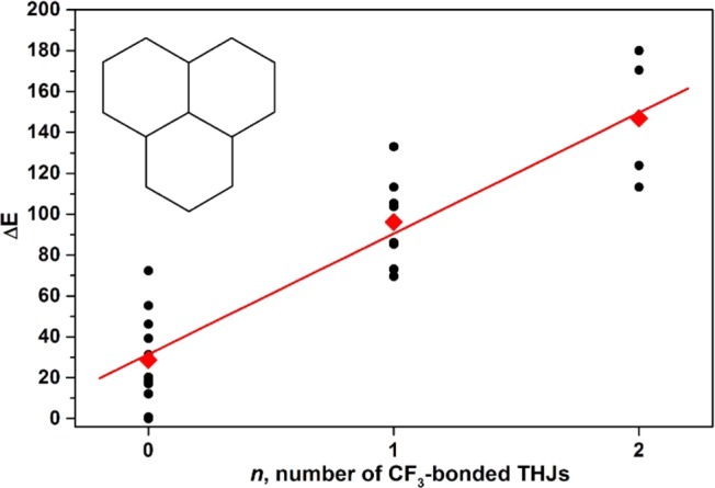
Correlation between the relative energies of C78(CF3)2 isomers (kJ·mol−1) and the number, n, of CF3 groups attached to THJs. Individual relative energies are shown as balck dots; the average relative energy for each value of n is shown as a red diamond.
The first studies of the trifluoromethylation of higher fullerenes either by pyrolysis with silver trifluoroacetate or by flow reaction with CF3I gas in hot tubes showed that adducts with 12 CF3 groups are formed predominantly.50,70 This number is exactly the number of pentagons present in each fullerene and is therefore the largest degree of addition accessible when no more than one CF3 group is added to one pentagon. 2D connectivity patterns in 19F NMR spectra proved that ribbon addition patterns are typical for higher fullerenes similar to C60 and C70, although short ribbons and p-C6(CF3)2 pairs are also not very uncommon.50,70 Structure elucidation of higher fullerene derivatives solely by 19F NMR data is complicated by the presence of at least two cage isomers starting from C76 and by the fact the reactions were usually performed with mixtures of fullerenes. Therefore, it is necessary to consider different carbon cages and different addition patterns for each carbon cage. However, the number of plausible structures can be reduced dramatically when several rules discussed above are applied. The following structural motifs are destabilizing and hence can be excluded: (i) addition to adjacent carbon atoms; (ii) addition to THJ carbon atoms; (iii) addition of more than one CF3 group to one pentagon. When these guidelines were applied to CF3 derivatives of higher fullerenes, the number of possible isomers reduced from millions to only a few, and realistic addition patterns could be then pinpointed on the basis of NMR data with the help of DFT calculations.
This approach was especially useful in the work described in ref (50), where trifluoromethylation of “insoluble” HHFs was performed. These fullerenes usually remain in the carbon soot after extraction of the soluble fullerenes presumably due to polymerization, and hence their molecular structures and even their existence as discrete cages before polymerization remained unknown. Their trifluoromethylation afforded soluble HHF(CF3)n derivatives, the cage isomers and addition patterns of which were determined by a combined NMR/DFT study. Trifluoromethylation was thus found to be a convenient method to prove the formation of some fullerenes in the arc discharge synthesis and to determine their molecular structures.
Figure 19 shows Schlegel diagrams of selected PFAFs based on the “insoluble” HHFs described in ref (50) and the soluble HHFs described in ref (70) (see Table 5 for the list of well-characterized HHF(RF)n derivatives). Their structures were determined by NMR/DFT analysis and confirmed for some of them by X-ray crystallography.57,69,96,108
Figure 19.

Schlegel diagrams of selected higher fullerene PFAFs with n ≤ 12. Reproduced with permission from ref (70). Copyright 2008 American Chemical Society.
Table 5. Perfluoroalkyl Derivatives of Higher Fullerenes.
| fullerene | characterized PFAFs | structural method | ref |
|---|---|---|---|
| C74-D3h(1) | C74(CF3)12 | X-ray, 19F NMR | (50,57) |
| C76-D2(1) | C76(CF3)6 | 19F NMR | (70) |
| C76(CF3)8, two isomers | 19F NMR | (70) | |
| C76(CF3)10, five isomers | 19F NMR | (70) | |
| C76(CF3)12 | 19F NMR | (70) | |
| C76(CF3)14 | X-ray | (90) | |
| C76(CF3)16, three isomers | X-ray | (90,165) | |
| C76(CF3)18, two isomers | X-ray | (90) | |
| C76-Td(2) | C76(CF3)12 | 19F NMR | (50) |
| C78-D3(1) | C78(CF3)10 | X-ray, 19F NMR | (70) |
| C78-C2v(2) | C78(CF3)10, two isomers | X-ray, 19F NMR | (70) |
| C78(C2F5)10 | X-ray | (78) | |
| C78-C2v(3) | C78(CF3)8 | 19F NMR | (70) |
| C78(CF3)12 | X-ray, 19F NMR | (70) | |
| C78-D3h(5) | C78(CF3)12 | X-ray, 19F NMR | (50,57) |
| C80-D2(2) | C80(CF3)12 | X-ray | (139c) |
| C80-C2v(5) | C80(CF3)12 | 19F NMR | (50) |
| C82-C2(3) | C82(CF3)12 | 19F NMR, X-ray | (50,96) |
| C82(CF3)16, two isomers | X-ray | (165) | |
| C82(CF3)18, two isomers | X-ray | (96) | |
| C82-C2(5) | C82(CF3)12 | 19F NMR | (50) |
| C84-D2d(4) | C84(CF3)12 | X-ray | (84b) |
| C84-D2(5) | C84(CF3)16 | X-ray | (166a) |
| C84-C2(11) | C84(CF3)12 | 19F NMR, X-ray | (69) |
| C84(C2F5)12 | X-ray | (83) | |
| C84-Cs(16) | C84(C2F5)12, two isomers | X-ray | (83,84b) |
| C84-C2v(18) | C84(C2F5)12 | X-ray | (83) |
| C84-D2(22) | C84(CF3)6 | X-ray | (167) |
| C84(CF3)12, two isomers | 19F NMR, X-ray | (70,107) | |
| C84(C2F5)12 | X-ray | (83) | |
| C84(CF3)14, two isomers | X-ray | (107) | |
| C84(CF3)16, four isomers | X-ray | (83,107) | |
| C84(CF3)20 | X-ray | (107) | |
| C84-D2d(23) | C84(CF3)4 | X-ray | (108) |
| C84(CF3)8 | X-ray | (108) | |
| C84(CF3)10 | X-ray | (108) | |
| C84(CF3)12 | X-ray | (108) | |
| C84(C2F5)12 | X-ray | (83) | |
| C84(CF3)14, two isomers | X-ray | (108) | |
| C84(CF3)16, two isomers | X-ray | (108) | |
| C84(CF3)18 | X-ray | (108) | |
| C86-C2(17) | C86(CF3)16, two isomers | X-ray | (81) |
| C86(CF3)18 | X-ray | (81) | |
| C88-C2(33) | C88(CF3)16 | X-ray | (139b) |
| C88(CF3)18 | X-ray | (86) | |
| C88(CF3)18 | X-ray | (139b) | |
| C90-C1(30) | C90(CF3)18 | X-ray | (168) |
| C90-C1(32) | C90(CF3)12 | 19F NMR | (70) |
| C90-Cs(35) | C90(CF3)14 | X-ray | (168) |
| C92-D2(82) | C90(CF3)16 | X-ray | (86) |
| C94-C2(61) | C94(CF3)20; two THJs | X-ray | (84a) |
| C96-C1(145) | C96(C2F5)12 | X-ray | (84a) |
Analysis of the CF3 addition patterns in higher fullerene PFAFs reveals predominant formation of long all-para ribbons. Typical patterns include the p11-ribbon in C74-D3h(1))(CF3)12, (C78-D3h(5))(CF3)12, and (C82-C2(5))(CF3)12, the p10-loop,p addition pattern in (C82-C2(5))(CF3)12, the p9-loop,p2 addition pattern in (C76-Td(2))(CF3)12, the double ribbon p5,p5 double ribbon addition pattern in (C82-C2(3))(CF3)12 and in two isomers of (C84-D2(22))(CF3)12). Out of two dozen isolated and characterized HHF(CF3)n compounds, only two had m-C6(CF3)2 hexagons: p3mp,p3mp-(C76-D2(2))(CF3)12 (76-12-2) and p5mp,p3-(C78-C2v(3))(CF3)12 (78-12-2). Another CF3 addition guideline proposed in ref (69) is the avoidance of additions to cage C atoms that form interpentagonal double bonds. Although such C atoms have high pyramidalization angles and therefore would be expected to be among the most reactive cage C atoms, their inclusion in ribbon addition patterns requires either the formation of DBIPs or additions to THJs.
Starting in 2009, extensive studies of higher fullerene perfluoroalkylation were reported by Troyanov and co-workers.78,83,84,86,90,96,139,166 A complete list of HHF(CF3)n ranging from C76(CF3)n to C96(CF3)n is given in Table 5. In many cases, X-ray structure determination afforded the first crystallographic proof of particular higher fullerene cages. Troyanov and coworkers used relatively harsh reaction conditions (e.g., reactions with ca. 6 bar of CF3I for 3 days in a sealed ampoule at 400–420 °C), which often resulted in a high degrees of perfluoroalkylation (n = 14–20). With 14 or more added CF3 groups, some pentagons must have more than one CF3 group, as shown in Figure 20. The rule limiting one CF3 group to one pentagon is obviously violated (Figure 20 shows Schlegel diagrams of selected PFAFs with 14–20 CF3 groups). A common motif for HHF(CF3)n derivatives with n > 12 is the presence of isolated double bonds connecting two 1,3-C5(CF3)2 pentagons. Another typical feature is the formation of isolated or nearly-isolated benzenoid hexagons, which are formed at the expense of additions to THJs. At the same time, the preference for all-para additions is preserved (as stated above, only a few derivative have m-C6(CF3)2 hexagons) and the addition to interpentagon double bonds is avoided (in fact, these double bonds often become isolated from the rest of the π-system).
Figure 20.

Schlegel diagrams of selected hollow higher-fullerene PFAFs with n ≥ 14. See Figures 12 and 16for color codes. RF groups attached to THJ carbon atoms are shown as empty circles. Semi-isolated and fully isolated benzenoid rings (five or six adjacent fullerene C(sp3) atoms, respectively) are shown shows as dashed and solid ovals; the positions of isolated double bonds (i.e., double bonds with four adjacent fullerene C(sp2) atoms) are also shown.
5.5. RF Addition to Endohedral Metallofullerenes
5.5.1. Derivatives of Monometallofullerenes
Perfluoroalkylation of two groups of endohedral metallofullerenes (EMF) has been reported so far. One group includes monometallofullerenes such as M@C82 (M = Y, Ce, Gd, etc.)30,66,75as well as Y@C2x EMFs with different cages sizes (2x = 60 to 74).106 These EMFs are paramagnetic in the pristine state (metal atom transfers three valence electrons to the carbon cage), and their perfluoroalkylation results in diamagnetic EMF(RF)n derivatives with an odd numbers of RF groups (typically n = 1–5). Structural studies of such derivatives are limited so far to 19F NMR spectroscopic studies of two isomers of Y@C82(CF3)5.30 According to 1D 19F and 2D 19F−19F COSY NMR data, both isomers had non-symmetric ribbon addition patterns. DFT computations of 56 ribbon isomers of Y@C82(CF3)5 in which para-C6(CF3)2 hexagons had various arrangement and locations on the Y@C82-C2v(9) cage revealed two stable isomers, which were 14 kJ·mol−1 more stable than the third one and at least 50 kJ·mol−1 more stable than 53 other isomers (see Figure 21). The molecular structures of Y@C74(CF3), Y@C70(CF3), and Y@C70(CF3)3 were proposed in ref (106) on the basis of UV–vis–NIR absorption spectra and DFT calculations.
Figure 21.
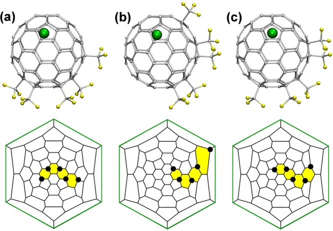
DFT-optimized molecular structures of three lowest energy isomers of Y@C82(CF3)5 (top row) and their Schlegel diagrams (bottom row) according to ref (30). The Y atoms are shown as green spheres. The hexagons to which the metal atom is coordinated are highlighted with green lines in the Schlegel diagrams.
5.5.2. Derivatives of Sc3N@C80
Trifluoromethylation of Sc3N@C80 was a subject of detailed studies in several reports.64,93,100,102The first characterized compounds were Sc3N@C80(CF3)2 (a mixture with the C80-Ih(7) or C80-D5h(6) cage isomers both present), the 19F NMR spectra of which indicated a symmetric addition pattern. DFT calculations showed that the lowest energy isomers for both carbon cages had para-C6(CF3)2 hexagon with CF3 groups avoiding THJ carbon atoms.64 Whereas the Sc3N cluster rotates freely inside the C80-Ih cage (barriers do not exceed 10 kJ·mol−1; see ref (169)), exohedral addition of CF3 groups dramatically changes the internal dynamics of the endohedral cluster. The two most stable optimized structures of Sc3N@C80(CF3)2 each have two of the three Sc atoms bonded to the cage C atom that is para to each of the cage C(CF3) atoms (see Figure 22), whereas conformers with different positions of the Sc3N cluster have much higher relative energies (from 13 to 65 kJ·mol−1).169,170 The exohedral RF groups and endohedral Sc3N cluster thus determine their mutual positions, and this influence is found in all PFA-Sc3N@C80 derivatives.
Figure 22.

Schlegel diagrams of structurally characterized Sc3N@C80(CF3)n derivatives (n = 2–18). RF groups attached to THJ cage C atoms are shown as empty circles. Semi-isolated and fully isolated benzenoid hexagons (i.e., with five and six fullerene C(sp3) atoms, respectively) are shown as dashed and solid ovals, respectively. Magenta circles mark the approximate positions of the Sc atoms with respect to the cage C atoms; in Sc-16-1, one Sc atom is disordered between two positions shown as half-transparent magenta circles. Unless otherwise noted, these are PFA derivatives of Sc3N@C80-Ih(7); two PFA derivatives of Sc3N@C80-D5h(6) are designated with “D5h”.
A significant step forward in the analysis of CF3 addition patterns to Sc3N@C80 was done in 2009, when the first single-crystal X-ray structures of Sc3N@(C80-Ih)(CF3)n derivatives (Sc-14-1 and Sc-16-1) were reported.88 This report was followed in 2011 by the structural elucidation of Sc-14-3 and Sc-16-2,100 and X-ray structures were also published for Sc-10-1 and Sc-12-1,93 and for three new isomers of Sc3N@C80(CF3)14.102 In addition, 19F spectroscopic characterization combined with an extensive computational study was reported for Sc-4, two isomers of Sc-8, Sc-10-1, two isomers of Sc-12, and Sc-14-2.93 In 2014, the structures of two more isomers of Sc3N@C80(CF3)14, Sc-14-7 and Sc-14-8, were determined by single-crystal X-ray diffraction.112 The authors of ref (112) pointed out that addition patterns of Sc-14-2 (determined by 19F NMR and DFT calculations) and Sc-14-4 (determined by X-ray) are very similar (see Figure 22) and that the structure of Sc-14-2 should probably be reassigned. The definitive statement would require the measurement of the 19F NMR spectrum of Sc-14-4, which was not reported. Whereas the majority of PFAFs belong to the Ih(7) cage isomer of Sc3N@C80, two structures with the Sc3N@C80-D5h(6) cage with 16 and 18 CF3 groups were also determined.100,112 Schlegel diagrams of structurally characterized Sc3N@C80(CF3)n derivatives are shown in Figure 22. Analysis of their addition patterns shows that the presence of the Sc3N cluster (which formally transfers six electrons to the carbon cage) has a dramatic effect on the distribution of CF3 groups on the fullerene surface. Similar to HHF(CF3) derivatives, the CF3 groups in Sc3N@C80(CF3)n tend to form ribbons. However, some of the other rules governing perfluoroalkylation of HHFs are not valid for Sc3N@C80. The general principles of multiple addition of CF3 groups to Sc3N@C80 compared with multiple additions to HHFs were formulated in ref (93) as follows:
(1) In Sc3N@C80(CF3)n derivatives with n ≥ 8, the ribbon addition patterns commonly include C5(CF3)2 pentagons. This differs from the behavior of hollow fullerene PFAFs where formation of C5(CF3)2 pentagons is usually avoided (at least for the fullerene(CF3)n with n ≤ 12).
(2) The addition of CF3 groups to triple-hexagon junctions (THJs) is known to be energetically unfavorable for hollow fullerenes. As discussed in section 5.4, there are only a few hollow fullerene derivatives with THJ-bonded CF3 groups, C76(CF3)14–18 and C94(CF3)20, and all have a high degree of trifluoromethylation.84a,90 In contrast, stable Sc3N@C80(CF3)x structures with THJ-bonded CF3 groups are formed for n ≥ 8. For instance, Sc-8-1, Sc-8-2, Sc-10-1, and Sc-12-1 all have one CF3 group bonded to a THJ, Sc-14 isomers have up to four THJ-bonded CF3 groups, and Sc-16-1 has eight functionalized THJs.
(3) “Isolated” CF3 groups are very rare for HHF(CF3)n (the only structures described are minor isomers of C70(RF)8,10: 70-8-12, 70-10-5, 70-10-11, and 70-10-14). In contrast, such isolated CF3 groups were found to be common for Sc3N@C80(CF3)x compounds, for example, for Sc-8-2, Sc-10-1, Sc-12-1, Sc-14-5. In all of these compounds, “isolated” CF3 groups are attached to THJ carbon atoms. Several other Sc3N@C80(CF3)x compounds with the isolated CF3 groups (according to 19F NMR spectroscopy) have also been obtained, but the details of their structures remain unknown.
Other common addition patterns include the formation of isolated or semi-isolated benzenoid hexagons (starting with n = 8) and the formation of isolated (Sc-16-1) or semi-isolated pentagons (Sc-12-2, Sc-14-1, Sc-14-6) at high degrees of trifluoromethylation. Importantly, CF3 addition pattern determines and fixes the position of the Sc3N cluster inside the fullerene cage because only a few metal-cage bonding sites are preserved.
6. Optical Excitations of PFAFs
6.1. UV–Vis–NIR Absorption Spectroscopy
UV–vis–NIR absorption spectroscopy is a relatively simple and very convenient spectroscopic method for the characterization of fullerenes and their derivatives. It is not therefore surprising that a vast majority of synthesized PFAFs, at least those with C60 and C70 cages, are characterized by absorption spectroscopy. Absorption spectra of fullerenes and their derivatives in the visible range are dominated by π–π* excitations and can deliver valuable information on the electronic and sometimes molecular structure of PFAFs. First, the lowest energy transition detectable in the absorption spectrum usually corresponds to the HOMO → LUMO excitation and therefore can be used to estimate the HOMO–LUMO gap (also referred to as “optical bandgap”). When absorption features are not well resolved and hence determination of the lowest peak position is not possible, the spectral onset can be used for a rough estimation. Analysis of the absorption spectra of PFAFs published in many reports on the synthesis of PFAFs shows that their lowest energy excitations usually span the range of 500–800 nm; that is, optical gaps of the majority of PFAFs are found in the range of 1.5–2.5 eV. Thus, PFAFs can be classified as medium-gap molecular semiconductors. The color of the PFAF solutions in organic solvents ranges from pale yellow to deep green.
Another important feature of UV–vis–NIR absorption spectra is their high structural sensitivity. Compounds with the same addition pattern usually exhibit an identical spectral pattern with insignificant variations of the band position and bandwidths irrespective of the substituents (if they are not chromophores themselves). Therefore, absorption spectra may be used for tentative structure elucidation by comparison with the spectra of compound with definitive molecular structure. As an example, Figure 23 shows that the UV–vis absorption spectra of Cs-C60(CF3)4O, Cs-C60(CF3)6 (60-6-2), C60Cl6, and C59N(CF3)5 exhibit pronounced similarity in the 300–600 nm range. All of these compounds have SPP or SPP-like addition patterns with isolated cyclopentadiene fragments and identical π-system for the non-functionalized part of the fullerene cage.
Figure 23.

Absorption spectra of fullerene derivatives with skew-pentagonal-pyramid addition patterns: Cs-C60(CF3)6,39 C60(CF3)4O,39 C59N(CF3)5,158 and C60Cl6.171
6.2. Fluorescence Spectroscopy
When it comes to a discussion of the luminescent properties of carbonaceous compounds, numerous aromatic fluorophores, carbon nanotubes, and carbon dots are much spoken about, whereas fullerenes usually remain in the shadows because of their very weak fluorescence. Fullerenes C60 and C70 have dipole-forbidden S0 ↔ S1 transitions,172 which lead to small values of radiative decay constants (e.g., kF = 2.7 × 10⁵ s–1 for C60 and 8.8 × 10⁵ s–1 for C70), in agreement with the Strickler–Berg rule.173 Furthermore, both fullerenes show high rates of intersystem crossing with almost quantitative formation of a triplet state. These two factors result in short fluorescence lifetimes (e.g., τF = 1.2 ns for C60 and 0.7 ns for C70) and very low fluorescence quantum yields (e.g., ΦF = ca. 0.0003 for C60 and ca. 0.0006 for C70 in toluene).173,174 Derivatization of the fullerenes reduces the symmetry and changes their π-system. Thus, absorptions of the derivatives are usually optically allowed, and hence higher values of kF can be reached. However, the relatively small perturbation of the fullerene π-system at early stages of functionalization preserves the low S0 → S1 absorption intensities and efficient intersystem crossing and leads to relatively low ΦF values.175
The first measurements of the PFAF fluorescence were reported in 2007.5 Fluorescence spectra were recorded for several isomers of C60(CF3)10 and helped in estimation of their optical gaps. However, numerical parameters (such as quantum yields) were not measured at that time.
A photophysical study of pristine and malonate-functionalized 70-10-1 was reported in 2010.99 The authors derivatized 70-10-1 via Bingel–Hirsch reaction and introduced a malonate group carrying two donor bis-π-extended tetrathiafulvalene (exTTF) moieties. 70-10-1 and its bare malonate derivative exhibited fluorescence with quantum yields of ∼0.02. In a 70-10-1/exTTF donor–acceptor dyad, fullerene-based fluorescence was partially quenched, and fluorescence lifetime was decreased from 3–3.5 to only 0.1 ns. Femtosecond transient absorption studies of the dyad proved photoinduced intramolecular electron transfer. The lifetime of the radical-ion pair varied from 289 ps in toluene to 23 ps in benzonitrile.
A dedicated study of the fluorescence of two isomers of C70(CF3)8 (70-8-1 and 70-8-2) and three isomers of C70(CF3)10 (70-10-1, 70-10-2, and 70-10-5) was published in 2013.176 The authors found that in contrast to the non-luminescent parent C70, C70(CF3)n compounds can be strong fluorophores, whose quantum yields strongly depend on the addition pattern (Figure 24). The quantum yield of fluorescence (ΦF) determined for 70-10-5 in toluene solution is as high as 0.68, which makes this compound the strongest fullerene fluorophore ever studied. For comparison, ΦF values of two other isomers are 0.05 (70-10-1) and 0.29 (70-10-2). Importantly, addition patterns of 70-10-1 and 70-10-2 are different from that of 70-10-5 only in location of one CF3 group (Figure 24), which however leads to 14-fold and 2-fold changes in their ΦF values, respectively. Thus, similar to reduction potentials, luminescent properties of PFAFs are to a large extent determined by addition pattern. Time-dependent DFT computations showed that among the five studied PFAFs, the highest quantum yields are found for molecules with (i) the largest oscillator strengths of S0 → S1 excitation and (ii) the largest energy gap between S1 and T1 states.
Figure 24.

Left: Absorption (black) and luminescence (red) spectra of 70-10-5. Middle: TD-DFT computed difference of the electronic density for the S0 → S1 excitation of 70-10-5. Right: Schlegel diagrams and photos of fluorescing solutions of three isomer of C70(CF3)10 along with the determined fluorescence quantum yields (from left to right: 70-10-1, 70-10-5, and 70-10-2). Red and blue dots in Schlegel diagrams denote CF3 groups whose positions are different in three isomers. Reproduced with permission from ref (176). Copyright 2013 American Chemical Society.
7. Electrochemical Properties of PFAFs
Fullerenes are known to be good electron acceptors with high electron affinity values (viz., gas-phase EAs of C60, C70, and C76 are 2.66, 2.68, and 2.88 eV, respectively).177 In solution at room temperature fullerenes exhibit several reversible single-electron reduction steps;178 under optimized conditions, up to six such steps can be measured for C60 and C70.179 Reduction results in the population of the low-energy unoccupied MOs with π* character, and hence the redox potentials are to a large extent determined by the topology of the π-system and can vary for the cage isomers in the range of 0.36 V as found for six isomers of C84.180
Derivatization of fullerenes via addition reactions converts the sp2-state of some carbon atoms into the sp3-state and hence inevitably results in a partial saturation of their π-system. Saturation of the π-system tends to decrease the electron affinity and shift the reduction potentials to more negative values. Besides, the chemical nature of the addends can be also important in determining the direction of the reduction potential shift after derivatization: electron-donating groups obviously shift the first reduction potential into the negative direction (in comparison to the pristine fullerene), whereas a positive shift can be anticipated for electron-withdrawing groups. The interplay of these factors determines the resulting shift of the reduction potential after the fullerene derivatization. For instance, the first reduction potentials of C60 derivatives with two C-sp3 cage atoms (monocycloadducts and C60R2 compounds) are usually near −0.10 V vs C600/–, but the values can reach −0.19 V for hydrosilylated adduct of C60 (electron-donating substituent)181 or +0.17 V for strongly electron-withdrawing tetracyanotetrahydrofuran addend.182
Considering the effect of the strong electron-withdrawing groups, examples of cyano- and fluorofullerenes are especially illustrative. The first reduction potentials of C60(CN)2 and C60(CN)4 are found at +0.14 and +0.28 V vs C600/–, respectively.183 For fluorofullerenes C60Fn (n = 2–48), the positive shift of E1/2(0/−) values increases gradually with increasing n and reaches +1.38 V for C60F48.184 However, Ccage–F bonds were found to be very unstable in the conditions of electron transfer, and fluorofullerenes tend to lose F atoms rapidly upon reduction. For groups with a medium electron-withdrawing strength, the interplay between the size of the π-system and the number of substituents can be more complex. For a series of C70(Ph)n derivatives (n = 2–10), Avent et al. reported a positive shift of +0.10 V vs C700/– for C70(Ph)2 and C70(Ph)4, but progressively negative shifts for a larger numbers of phenyl groups reaching −0.99 V for C70(Ph)10.185 The authors proposed that for n = 6–10, saturation of the π-system outweighed the weakly electron-withdrawing effect of the phenyl groups.
Addition of two or more single-bonded groups and two or more cycles to C60 can modify the π-system of the fullerene core in a different way depending on the addition pattern. However, before the results of electrochemical properties of PFAFs were published, this factor was not well studied, mainly because of the limited number of the well-characterized isomers of fullerene derivatives suitable for dedicated electrochemical studies. However, the scarce data available before 2007184b,186 (e.g., isomers of bis-pyrrolidinofullerene adducts186e or 1,7- vs 1,9-C60R2 derivatives186b,186d,186f,186g) showed that the first reduction potential of isomers with different addition patterns can vary by 0.16 V (this was considered by the authors to be a large difference). Although an explanation of these variations was not given at that time, these examples show that the two-factor paradigm “π-system/nature of the group” cannot provide the correct interpretation of the electrochemical properties of fullerene derivatives with multiple electron-withdrawing groups of medium strength and should be revised.
The unprecedented number of PFAFs provided a unique opportunity to discover the influence of the addition pattern, the number of added groups, and their electron-withdrawing nature on the redox properties of fullerene derivatives.
7.1. Reduction Potentials of Trifluoromethylfullerenes (TMFs)
7.1.1. C60(CF3)n Derivatives
The first study of the electrochemical properties of C60(CF3)n derivatives in 2005 was published (CVs of 60-2-1, 60-10-1, 60-10-2, and 60-10-3 were reported), and revealed the characteristic redox features of these compounds,184c which were then confirmed and solidified in a number of following works. First, in contrast to fluorofullerenes, C60(CF3)n derivatives exhibit several reversible reductions at room temperature in DCM or oDCB in anaerobic conditions, pointing to the high stability of the anion radicals of TMFs (ESR studies showed that some TMF anion radicals were stable for hours or days in fluid solution at room temperature115). Second, for a majority of TMFs, reduction potential is shifted positively vs C600/–, which agrees with the electron-withdrawing nature of CF3 groups. Third, the first reduction potential of three isomers of C60(CF3)10 spanned the unprecedentedly large range of 0.27 V, indicating that the addition pattern plays a crucial role in determination of the redox potentials. These conclusions were then confirmed and developed in a dedicated study of electrochemical properties of 18 C60(CF3)n derivatives (n = 2–12) published in 2007.5 The work reported on the redox properties of 60-2-1, 60-4-1, two isomers of 60-6, five isomers of 60-8, six isomers of 60-10, and three isomers of 60-12 and revealed that the range of the E1/2(0/−) values for different isomers can be as high as 0.50 V (see Figure 25 for CV curves of 60-10 isomers and Table 6 for a complete list of all experimentally measured reduction potentials of PFAFs). 60-10-1 exhibited the largest positive shift of the first reduction potential vs C600/–, +0.57 V, but a few compounds (60-6-2, 60-12-1, 60-12-3) exhibited a negative shift of the first reduction potential (the most negative value was for 60-12-1). The fact that the range of the E1/2(0/−) values within a group of isomers is comparable to the range of E1/2 values spanned by the whole set of C60(CF3)n derivatives irrespective of n (see Figure 26) clearly showed that there is no correlation between the number of CF3 groups and TMF reduction potentials. Therefore, the addition pattern plays a much more important role than the number of substituents. At the same time, a DFT study revealed a very good linear correlation between the E1/2(0/−) and the LUMO energy of the neutral TMF (R2 = 0.98; see Figure 26), which allowed the prediction of E1/2(0/−) values with the precision of 0.02–0.03 V. As a result of these observations, the addition pattern, the topology of the π-system, and their influence on the spatial localization of the LUMO were analyzed to explain the structure–property relationships. Note that first reduction potentials correspond to gas-phase electron affinities corrected for the solvation of the neutral molecule and the anion radical, but in many cases a much more simple quantity, the neutral-molecule LUMO energy, produced a good correlation with E1/2(0/−) values and was used for the analysis. See section 7.3.1 for a discussion of electron affinities, solvation energies, and reduction potentials.
Figure 25.

Cyclic voltammograms of five isomers of C60(CF3)10 (DCM solution, TBABF4 electrolyte, room temperature). Reproduced with permission from ref (5). Copyright 2007 American Chemical Society.
Table 6. Reduction Potentials of PFAFsa.
| compound | ref | gapb | E(LUMO)b | E1/2(0/−) | E1/2(1−/2–) | E1/2(2−/3–) | solventc |
|---|---|---|---|---|---|---|---|
| C60 | (104) | 1.639 | –4.379 | 0.00 | –0.40 | –0.85 | DCM |
| (104) | 0.00 | –0.39 | –0.85 | oDCB | |||
| (104) | 0.00 | –0.41 | PhCN | ||||
| C60(CF2) | (187) | 0.15 | –0.19 | –0.79 | oDCB | ||
| C60(CF2)2 | (187) | 0.14 | –0.20 | –0.80 | oDCB | ||
| 60-2-1 | (104) | 1.430 | –4.592 | 0.15 | –0.30 | –0.80 | DCM |
| (104) | 0.13 | –0.28 | –0.81 | oDCB | |||
| (104) | 0.13 | –0.32 | PhCN | ||||
| 60-2-1-C2F5 | (104) | 1.431 | –4.599 | 0.17 | –0.24 | –0.78 | DCM |
| (104) | 0.13 | –0.30 | –0.82 | oDCB | |||
| (104) | 0.13 | –0.31 | PhCN | ||||
| 60-2-1-n-C3F7 | (104) | 1.427 | –4.598 | 0.13 | –0.28 | –0.82 | DCM |
| (104) | 0.13 | –0.29 | –0.82 | oDCB | |||
| (104) | 0.13 | –0.30 | PhCN | ||||
| 60-2-1-i-C3F7 | (104) | 1.435 | –4.589 | 0.14 | –0.29 | –0.82 | DCM |
| (104) | 0.13 | –0.31 | –0.83 | oDCB | |||
| (104) | 0.10 | –0.36 | PhCN | ||||
| 60-2-1-n-C4F9 | (104) | 1.425 | –4.607 | 0.11 | –0.31 | –0.84 | DCM |
| (104) | 0.13 | –0.30 | –0.83 | oDCB | |||
| (104) | 0.14 | –0.30 | PhCN | ||||
| 60-2-1-s-C4F9 | (104) | 1.434 | –4.595 | 0.14 | –0.29 | –0.83 | DCM |
| (104) | 0.11 | –0.32 | –0.85 | oDCB | |||
| (104) | 0.10 | –0.36 | PhCN | ||||
| 60-2-1-n-C8F17 | (104) | 1.425 | –4.609 | 0.15 | –0.27 | –0.81 | DCM |
| (104) | 0.12 | –0.30 | –0.82 | oDCB | |||
| (104) | 0.13 | –0.34 | PhCN | ||||
| 60-4-1 | (5) | 1.443 | –4.682 | 0.17 | –0.26 | –1.01 | DCM |
| 60-4-4-i-C3F7 | (94) | 1.242 | –4.786 | 0.32 | –0.32 | –0.80 | oDCB |
| 60-4-5-i-C3F7 | (94) | 1.444 | –4.680 | 0.20 | –0.26 | –0.78 | oDCB |
| 60-6-1 | (5) | 1.445 | –4.796 | 0.26 | –0.28 | –0.93 | DCM |
| 60-6-2 | (5) | 1.859 | –4.378 | –0.07 | –0.53 | –1.02 | DCM |
| C59N-5 | (158) | 1.872 | –4.374 | –0.05 | –0.54 | DCM | |
| 60-6-3-i-C3F7 | (94) | 1.369 | –4.830 | 0.32 | –0.32 | –0.80 | oDCB |
| 60-6-5-i-C3F7 | (94) | 1.461 | –4.735 | 0.32 | –0.32 | –0.80 | oDCB |
| 60-6-8-i-C3F7 | (94) | 1.187 | –4.900 | 0.32 | –0.32 | –0.80 | oDCB |
| 60-8-1 | (5) | 1.498 | –4.850 | 0.33 | –0.19 | –0.66 | DCM |
| 60-8-2 | (5) | 1.482 | –4.912 | 0.32 | –0.19 | –0.79 | DCM |
| 60-8-3 | (5) | 1.333 | –5.017 | 0.45 | –0.03 | –0.96 | DCM |
| 60-8-4 | (5) | 1.701 | –4.585 | 0.06 | –0.38 | –1.06 | DCM |
| 60-8-5 | (5) | 1.420 | –4.863 | 0.31 | DCM | ||
| 60-10-1 | (5) | 1.139 | –5.129 | 0.57 | –0.07 | DCM | |
| 60-10-2 | (5) | 1.550 | –4.894 | 0.32 | –0.47 | DCM | |
| 60-10-3 | (5) | 1.662 | –4.754 | 0.17 | –0.44 | DCM | |
| 60-10-4 | (5) | 1.636 | –4.529 | 0.07 | –0.47 | DCM | |
| 60-10-5 | (5) | 1.748 | –4.638 | 0.12 | –0.46 | DCM | |
| 60-10-6 | (5) | 1.445 | –4.922 | 0.33 | –0.34 | DCM | |
| 60-10-8 | (115) | 1.429 | –4.904 | 0.28 | –0.36 | –0.98 | oDCB |
| 60-12-1 | (5) | 2.245 | –4.278 | –0.16 | DCM | ||
| 60-12-2 | (5) | 1.614 | –4.919 | 0.32 | –0.39 | DCM | |
| 60-12-3 | (5) | 2.086 | –4.331 | –0.13 | –0.59 | DCM | |
| C70 | (68) | 1.703 | –4.315 | 0.00 | –0.40 | –0.80 | DCM |
| 0.00 | –0.37 | –0.78 | oDCB | ||||
| open-C70(CF2) | (110) | 0.15 | –0.18 | –0.76 | oDCB | ||
| closed-C70(CF2) | (110) | 0.01 | –0.28 | –0.75 | oDCB | ||
| 70-2-1 | (68) | 1.372 | –4.697 | 0.28 | –0.14 | –0.71 | DCM |
| 70-2-1-C2F5 | (116) | 1.369 | –4.706 | 0.27 | –0.16 | –0.73 | DCM |
| 70-2-1-i-C3F7 | (94) | 1.367 | –4.708 | 0.28 | –0.15 | –0.79 | oDCB |
| 70-2-2 | (68) | 1.232 | –4.533 | 0.12 | –0.26 | –0.74 | DCM |
| 70-2-2-i-C3F7 | (94) | 1.230 | –4.528 | 0.10 | –0.31 | –0.83 | oDCB |
| 70-4-1 | (68) | 1.334 | –4.648 | 0.21 | –0.18 | –0.77 | DCM |
| 70-4-3-i-C3F7 | (94) | 1.367 | –4.764 | 0.30 | –0.15 | –0.64 | oDCB |
| 70-4-4-i-C3F7 | (94) | 1.252 | –4.896 | 0.49 | 0.00 | –0.77 | oDCB |
| 70-6-1 | (68) | 1.333 | –4.731 | 0.30 | –0.14 | –0.57 | DCM |
| 70-6-2 | (68) | 1.304 | –4.758 | 0.34 | –0.13 | –0.48 | DCM |
| 70-6-3 | (68) | 1.560 | –4.639 | 0.17 | –0.27 | DCM | |
| 70-8-1 | (68) | 1.707 | –4.555 | 0.04 | –0.41 | –1.04 | DCM |
| 70-8-2 | (68) | 1.263 | –4.829 | 0.31 | –0.21 | –1.28 | DCM |
| 70-10-1 | (68) | 2.071 | –4.351 | –0.11d | –0.66 | DCM | |
| 70-10-2 | (68) | 1.823 | –4.536 | –0.01 | –0.50 | DCM | |
| 70-10-3 | (68) | 1.679 | –4.588 | 0.04 | –0.41 | DCM | |
| 70-10-4 | (68) | 1.628 | –4.599 | 0.08 | –0.48 | –0.86 | DCM |
| 70-10-5 | (68) | 1.370 | –4.813 | 0.28 | –0.21 | –1.11 | DCM |
| 70-12-1 | (68) | 1.700 | –4.664 | 0.09 | –0.46 | –0.91 | DCM |
| 70-12-2 | (68) | 1.671 | –4.676 | 0.07 | –0.47 | –0.98 | DCM |
| 70-12-3 | (68) | 1.634 | –4.777 | 0.26 | –0.37 | –0.90 | DCM |
| 70-12-4 | (68) | 1.687 | –4.774 | 0.25 | –0.41 | –0.90 | DCM |
| Sc3N@C80 | 1.463 | –3.907 | 0.00 | –0.36 | –1.11 | oDCB | |
| Sc-2 | (188) | 1.149 | –4.184 | 0.10 | –0.39 | –0.88 | oDCB |
| Sc-4-1 | (93) | 1.103 | –4.247 | 0.20 | –0.29 | –0.77 | oDCB |
| Sc-10-1 | (93) | 1.079 | –4.535 | 0.42 | –0.06 | –0.85 | oDCB |
| Sc-12-1 | (93) | 1.238 | –4.423 | 0.32 | –0.12 | –0.72 | oDCB |
The values for PFAF derivatives are given vs the E1/2(0/−) of the parent non-functionalized fullerene, selected E1/2(0/−) values vs Fe(Cp)2+/0 are: C60, −0.98 V in DCM and −1.06 V in oDCB; C70, −0.98 V in DCM, −1.06 V in oDCB; Sc3N@C80, −1.26 V in oDCB.
PBE/TZ2P computed value.
DCM = dichloromethane; oDCB = o-dichlorobenzene; PhCN = benzonitrile.
Irreversible.
Figure 26.

Correlation between the first reduction potentials of C60(CF3)n derivatives and DFT-computed LUMO energy (all values are relative to C60). The inset is a plot of E1/2(0/−) values vs the number of CF3 groups. Reproduced with permission from ref (5). Copyright 2007 American Chemical Society.
As discussed in section 5, the para additions typical for CF3 groups inevitably result in the formation of DBIPs, which can be classified into two groups: terminal (t-DBIPs) with three adjacent fullerene C(sp3) atoms (shown in blue in Figure 27; these are usually the shortest bonds in the molecule) and non-terminal nt-DBIPs with two adjacent fullerene C(sp3) atoms (shown in red in Figure 27).
Figure 27.

Double bonds in pentagons (DBIPs) formed as the result of para CF3 additions: (a) a terminal DBIP (t-DBIP, highlighted with a blue oval; (b) a non-terminal DBIP (nt-DBIP, highlighted with a red oval); (c) the Schlegel diagram for 60-10-2 with t-DBIPs and nt-DBIPs highlighted as blue and red lines, respectively.
Careful analysis of the spatial localization of LUMO in a large series of C60(CF3)n derivatives showed that LUMO is always anchored to nt-DBIPs, and hence the number and relative position of nt-DBIPs determine the energy of the LUMO and consequently the first reduction potential of the PFAF molecule. When only one nt-DBIP is present, the delocalized LUMO pattern resembles that of acenaphthalene (Figure 28), and E1/2(0/−) potential is shifted positively vs C600/– by 0.06–0.17 V. Besides 60-2-1, this situation was found in all PFAFs with p(mp)x ribbons, including 60-4-1 (pmp), 60-8-4 (pmpmp), and 60-10-5 (pmpmpmp).
Figure 28.

Polyaromatic hydrocarbon-like fragments and their LUMOs: (a) acenaphthalene, (b) fulvene, (c) pentafulvalene. Examples of PFAFs with different types of LUMOs and their LUMO isosurfaces: (d,g) 60-2-1 with an acenaphthalene-like LUMO; (e,h) 60-6-1 with a fulvene-like LUMO; and (f,i) 60-4-4-i-C3F7 with a pentafulvalene-like LUMO motif.
A large number of PFAFs have addition patterns with p3 fragments. In the p3 moiety, two nt-DBIPs are located in one pentagon; that is, they form a cyclopentadiene fragment communicating with the rest of the fullerene π-system through the fifth C-sp2 atom of the pentagon. When this fragment is present, LUMO of PFAF is largely localized in the vicinity of the cyclopentadiene fragment and resembles the LUMO of fulvene, as shown in Figure 28. The first reduction potentials of C60(CF3)n derivatives with such LUMO (e.g., p3mp60-6-1, p3mpmp60-8-1 and 60-8-3, p3mpmpmp60-10-2, p3mpmpmpmp60-12-2) are shifted positively vs C600/– by 0.26–0.33 V. Note that communication of the p3 moiety to the fullerene π-system is crucial for the large positive shift of the reduction potential: in 60-10-3, the fulvene fragment is isolated from the rest of the π-system, and the E1/2(0/−) potential of 60-10-3 is only 0.17 V vs C600/–. Moreover, when a cyclopentadiene fragment is isolated from the fullerene π-system (and hence p3 moiety is formed by terminal DBIPs as in 60-6-2, 60-10-4, 60-12-3), LUMO is localized on other parts of the molecule.
An interesting situation appears when the addition pattern includes both a p3 moiety and single nt-DBIP (e.g., a p3 ribbon with an isolated p or pmp fragment such as found in p3mp,p60-8-2 and 60-8-5, p3mpmp,p60-10-1, p3mp,pmp60-10-6, etc.). In this case, the shape of the LUMO and the reduction potential depend on the relative position of these fragments. When they are far from each other, the LUMO has a fulvene-like motif and the reduction potential is similar to those of compounds with a p3 moiety described in the previous paragraph (the LUMO+1 orbital in this case has an acenaphthalene-like shape and is anchored to the single nt-DBIP). However, when the p3 moiety and the single nt-DBIP are close to one another, the LUMO is strongly stabilized by delocalization between these fragments resulting in an enhancement of the positive E1/2(0/−) shift. This situation is found in 60-8-3 (+0.45 V vs C600/–) and 60-10-1 (+0.57 V vs C600/–), the latter exhibiting the most positive reduction potential among all PFAFs, comparable to the values reported for C60F36 isomers.184b DFT calculations predicted that a hypothetical isomer of C60(CF3)8, with two p3 moieties in conjugation, could have a reduction potential of 0.73 V, but this compound has not yet been isolated.
In summary, reduction potentials of C60-based PFAFs can be very well understood taking into account their addition patterns, and in particular the number and relative position of nt-DBIPs. The only PFAFs not considered so far are those that have no nt-DBIPs. Analysis of the redox potentials of three such C60(CF3)n compounds, 60-6-2, 60-12-1, and 60-12-3, shows that in this case E1/2(0/−) values are shifted negatively vs C600/–.
7.1.2. C70(CF3)n Derivatives
The redox properties of C70(CF3)n derivatives are similar to those of C60(CF3)n in that they also show several reversible reductions and a positive shift of E1/2(0/−) potentials vs C700/–.68,116 The only compound that does not follow these guidelines is 70-10-1, whose first reduction of which is irreversible and cathodically shifted by 0.11 V vs C700/−. Similar to C60(CF3)n derivatives, the range of E1/2 values for isomers of C70(CF3)n can be as high as 0.35 V for the first reduction and 0.45 V for the second reduction (the highest ranges are found for 70-10 isomers).
The interpretation of C70(CF3)nE1/2 values in terms of their addition patterns and LUMO localization is not as straightforward as it is for C60(CF3)nE1/2 values because C70(CF3)n addition patterns are much more diverse. In particular, for C70 1,4-additions do not necessarily form DBIPs. Yet, when nt-DBIPs are formed in C70(CF3)n derivatives, their crucial role in determining reduction potentials becomes apparent. An illustrative example is the pair of C70(CF3)8 isomers 70-8-1 and 70-8-2. The former has one nt-DBIP, and its LUMO resembles that of the acenaphthalene-like fragments in C60(CF3)n derivatives with one nt-DBIP (Figure 29). In contrast, 70-8-2 has several DBIPs near the C70 equator, and its LUMO is more delocalized and resembles the LUMO of the linear acene tetracene. As a result, the LUMO of 70-8-2 is 0.27 eV lower in energy, and its E1/2(0/−) value is 0.27 V more positive than for 70-8-1. Similar to C60(CF3)n derivatives, the most negative first reduction potentials for the entire C70(CF3)n family are found for two compounds with no nt-DBIPs, 70-10-1 (E1/2(0/−) = ca. −0.11 V) and 70-10-2 (E1/2(0/−) = −0.01 V).
Figure 29.

Fragments of the DFT-predicted structures and the DFT-predicted LUMOs for 70-8-1 and 70-8-2. The numbers in the structure fragments are cage C–C distances in pm (the black circles indicate the cage C atoms to which the CF3 groups are attached). Reproduced with permission from ref (68). Copyright 2008 Wiley-VCH Verlag GmbH & Co. KGaA, Weinheim.
7.1.3. Sc3N@C80(CF3)n
Electrochemical studies are reported so far for four Sc3N@C80(CF3)n derivatives (Sc-80-x) with n ranging from 2 to 14.64,93,188 All derivatives exhibited one to three reversible reductions. The first oxidation steps of Sc3N@C80(CF3)n were also accessible in oDCB solution at room temperature (unlike oxidations of empty fullerene PFAFs, which have not been achieved so far), and the second reversible oxidation step was also observed for Sc-80-2. Trifluoromethylation of Sc3N@C80 induced a positive shifts of first reduction potentials, from +0.10 V in Sc-8-2 to +0.42 in Sc-10-1 (note that the E1/2(0/−) value of Sc-12-1, +0.31 V, is less positive than for Sc-10-1). At the same time, the first oxidation potentials of Sc-2-1 and Sc-4-1 are shifted negatively with respect to the E1/2(+/0) value of Sc3N@C80 by −0.16 and −0.04 V, respectively, whereas the first oxidation potentials of Sc-10-1 and Sc-12-2 are more positive than for Sc3N@C80 by 0.27 and 0.36 V, respectively.
7.2. ESR and Vis–NIR Spectroscopic Studies of PFAF Anions
7.2.1. Electron Spin Resonance
The first electrochemical study in 2005184c showed that anions of PFAFs can be sufficiently stable to allow their spectroscopic studies by electron spin resonance (ESR) spectroscopy and absorption spectroscopy in the visible and near-infrared (vis–NIR) range. In the ESR spectra, anion radicals of non-derivatized fullerenes exhibit single-line signals whose line width may be rather large due to the Jahn–Teller effect when degenerate LUMO is partially filled (e.g., ESR line width of C60– at room temperature is ca. 40 G189). The 13C hyperfine structure in the ESR spectra of the charged radicals of fullerenes is usually not sufficiently informative for a detailed analysis of the spin density distribution because of the low natural abundance of 13C isotope. The situation can be changed when fullerene is exohedrally functionalized with substituents carrying magnetic nuclei such as 19F.68,110,115,116,184c,187
The first ESR spectrum of the anion radical of PFAF with well-resolved 19F-hyperfine structure was reported in 2005 in the in situ ESR spectroelectrochemical study of 60-10-3.184c Although spin density in PFAF anions is mainly localized on the carbon cage, the apparent 19F hyperfine constant a(19F) in 60-10-3– was ca. 0.5 G. Eventually ESR spectra were reported for 14 anion radicals of empty PFAFs prepared either electrochemically or chemically by a reaction with cobaltocene. Some of them showed complex hyperfine structure attributed to CF3 groups (see Figure 30a for the ESR spectrum of the anion radical 60-10-3–). The rich hyperfine structure contains information on the spin density distribution in the radical anions, which can be related to the spatial distribution of LUMO in the neutral compounds. However, interpretation of such rich ESR spectra is not straightforward. Although fast rotation of CF3 groups at the ESR time scale averages the value in each group and hence simplifies the situation, unravelling the hyperfine structure of non-symmetric anion radicals with 10 CF3 groups (such as shown in Figure 30b) still requires finding 10 independent a(19F) values. Obtaining these parameters as a result of the fitting (i.e., solving inverse problem) can quickly become meaningless for such number of parameters. To solve this problem, in ref (115) the authors first computed a(19F) values at the B3LYP level of theory with specially tailored basis sets and then used computed values as an initial approximation in the fitting procedure. This approach allowed obtaining physically meaningful sets of a(19F) values for anion radicals with well-resolved hyperfine structure (Figure 30b). Computational study also allowed analysis of the nature of hyperfine couplings in these compounds. Comparison of unrestricted formalism (U-B3LYP; different spins have different orbitals) and restricted-orbital formalism (RO-B3LYP; spin-up and spin-down orbitals are identical except for a SOMO) showed that the polarization contribution is significant and can reach up to 30–40% of the values for individual fluorine atoms (Figure 30c).
Figure 30.

(a) Experimental and simulated ESR spectra of 60-10-3–; (b) Schlegel diagram of 60-10-3 with DFT-computed (black) and experimental (red) a(19F) values for each CF3 group. Blue and green circles show major LUMO lobes. (c) Spin density in 60-10-3– and a(19F) values of individual fluorine atoms computed at the U-B3LYP (black) and RO-B3LYP levels. Reproduced with permission from ref (115). Copyright 2010 American Chemical Society.
Well-resolved ESR spectra were reported in ref (116) for the anion radicals of C70(CF3)2 and C70(C2F5)2. The ESR spectrum of the former exhibited a quartet with an a(19F) value of 0.32 G and a 1:3:3:1 intensity ratio, which indicated that only one CF3 group is significantly coupled to the unpaired electron. The radical C70(CF3)2– is also a rare example of a PFAF anion radical that exhibits a plethora of well-resolved 13C satellites lines in its ESR spectrum (Figure 31). DFT-calculated 13C coupling constants allowed interpretation of the data and showed that the largest a(13C) values are found for carbon atoms in the CF3 groups (6.40 and 4.46 G), followed by several carbon atoms near the C70 equator (Figure 31).
Figure 31.

(a) ESR spectrum of 70-2-1– with enhanced 13C satellite structure (red and blue lines), the inset shows a fragment of the Schlegel diagram with the numbers of C atoms with the largest a(13C) values; (b) spin density in 70-2-1– and a(13C) values of selected carbon atoms. Based on results reported in ref (116).
ESR studies were also reported for anion radicals of Sc3N@C80(CF3)n (n = 2, 10, 12) and for the trianion radical of Sc3N@C80(CF3)2.93,188 ESR spectra of these species had rich hyperfine structure due to 45Sc nuclei (I = 7/2) of the endohedral cluster, and weaker 19F-based splitting could not be seen. Comparison of the a(45Sc) values to that of the Sc3N@C80– anion radical showed that with the increase of the number of CF3 groups the spin density in the anion radicals of Sc3N@C80(CF3)n shifted systematically from the endohedral cluster to the carbon cage.
7.2.2. Vis–NIR Absorption Spectroscopy
The anionic states of fullerenes exhibit characteristic absorptions in the near-IR range originating from LUMO → LUMO+N excitations (here LUMO is the lowest-unoccupied molecular orbital of the pristine fullerene, which is populated upon reduction).190 Such excitations are absent in the pristine fullerene, which makes absorption spectroscopy an especially convenient tool for spectroelectrochemical studies. Since derivatization changes the π-system of a fullerene via saturation of some C(sp2) atoms, hence the NIR absorption features of the anion can also be substantially affected. Vis–NIR absorption spectra in the anionic states were reported for a series of C60(CF3)n derivatives (n = 2–12)115,191 and for C70(CF3)2.116
All known PFAF anion radicals exhibited new absorption features in the NIR range, but the spectral patterns were different than those of anionic C60 and C60 cycloadducts. While the latter are known to exhibit one NIR band at 1080/950 nm (C60–/C602–)190 or at ca. 1010 nm (monoanions of cycloadducts),175b two NIR bands are observed in the spectra 60-2-1 and 60-4-1 in the reduced states.115 The monoanion of 60-2-1 has two major NIR bands at 942/1550 nm, which are shifted to 880/1336 nm in the dianion. Likewise, 60-4-1 absorbs light at 790/1530 nm in the monoanionic state and at 737/1255 nm in the dianionic state. Time-dependent DFT calculations showed that the intense NIR band of C60–/C602– corresponds to the 2-fold degenerate transition from the single-occupied MO to the LUMO+1-derived orbital. Lowering of the symmetry by addition of several groups, while retaining to a large extent an electronic structure of the fullerene, results in the splitting of the NIR band of C60–/C602–. This was indeed found for the anions of the C60(CF3)2,4 derivatives. Derivatives with a larger number of CF3 groups (6–10) exhibited one intense NIR band with position depending on the number groups and isomeric structure.115 The anion and dianion of 60-6-1 have NIR absorptions at 1850 and 1355 nm, respectively, whereas absorptions of C60(CF3)8– and C60(CF3)10– isomers are usually limited to 1000 nm. Absorption spectra of S6-C60(CF3)12– and S6-C60(CF3)122– reported recently by Konarev et al. exhibited broad absorption features at 750 and 648 nm, respectively.191
7.3. Reduction Potentials of RF Derivatives
7.3.1. Substituent Effect in 1,7-C60(RF)2 Compounds
Variation of the perfluoroalkyl groups in PFAFs can influence redox properties in at least two ways. First, as discussed in section 5, the size of the RF groups affects addition patterns and hence electrochemical properties. Second, electron-withdrawing strength of perfluoroalkyl groups can depend on the chain lengths. Obviously, the role of the second factor can be revealed by analyzing redox potentials of the isostructural compounds. However, until recently, the synthesis of PFAFs with large perfluoroalkyl groups was not well developed because of the complex processes/partial decomposition in high temperature conditions. So far, comparison of redox potentials of isostructural PFAFs with different RF groups can be done only for bis-adducts. The first comparison between CF3 and C2F5 study was reported in 2008 and showed that reduction potentials of isostructural 70-2-1 and 70-2-1-C2F5 are virtually identical.116 The study of 1,7-C60(i-C3F7)2 also did not show a noticeable deviation of its reduction potential in comparison to C60(CF3)2.94
The development of the new method of PFAF synthesis based on reaction of RFI with fullerene in the presence of a copper-powder promoter in degassed refluxing oDCB in a sealed tube at 190 °C afforded isolation of the series of 1,7-C60(RF)2 compounds with long-chain RF groups (up to n-C8F17), and hence a systematic study of their redox properties became possible (Figure 32).104 The electrochemical study was also augmented by the measurements of their gas-phase electron affinities (EAs), thus allowing one to address a question of the role of solvent in the redox potentials of PFAFs.
Figure 32.

LUMO energies, solvation energies (ΔΔEsolv), reduction potentials (E1/2), and electron affinities of 1,7-C60(RF)2 compounds; all values are relative to C60(CF3)2. The solid data points are experimental values (uncertainties are shown as error bars); the hollow data points are DFT-predicted values. The lines are linear least-squares fits to DFT-predicted results. Note that each plot has a y-axis interval of 0.10 eV or V, either from 0.00 to 0.10 or from 0.05 to 0.05.The slopes were derived by assigning each RF group an x-axis value of successive integers as follows: CF3 = 1, C2F5 = 2, etc. Reproduced with permission from ref (104). Copyright 2012 The Royal Society of Chemistry.
High precision of the EA measurements (the experimental uncertainty was less than 0.01 eV) showed that EAs of C60(RF)2 derivatives monotonically increase with the perfluoroalkyl chain length from 2.920(8) eV for RF = CF3 to 3.010(8) eV for RF = n-C8F17. It was also found that EAs of C60(RF)2 derivatives with n-perfluoroalkyl groups are higher than those with branched groups (i-C3F7 and s-C4F9). DFT calculations of EA values reproduced these trends. Surprisingly, reduction potentials measured by cyclic voltammetry did not correlate with the results of EA measurements and showed that all C60(RF)2 derivatives exhibited almost identical E1/2(0/−) values (within 0.03 V). The lack of correlation was explained by the role of solvation energy. DFT computations of solvation energies in the framework of polarizable continuum model showed that solvation energy of PFAF anions is decreasing with the increase of the RF chain length. The decrease of solvation energy compensates for an increase of the EA along the series, and hence reduction potentials remain virtually constant.
7.3.2. The Role of Addition Pattern for Bulky RF Groups: i-C3F7 Derivatives
As discussed in detail in section 5, CF3 groups tend to add to fullerenes forming ribbons of edge-sharing meta- and/or para-C6(CF3)2 hexagons. A consequence relevant to the electron-accepting properties of PFAFs is the reduced number of nt-DBIPs formed in such ribbon-like addition patterns. Although each pair of RF groups added to C60 produces one DBIP, in ribbon addition patterns some of these DBIPs become t-DBIPs and do not influence the localization of LUMO. As a result, C60(CF3)n derivatives usually have only one or two nt-DBIPs. At the same time, rare examples of compounds with three nt-DBIPs show that for some addition patterns strong stabilization of the LUMO and enhancement of electron-accepting property of the compounds can take place (the examples are 60-8-3 and 60-10-1). Therefore, it would be desirable, whenever possible to produce the strongest PFAF acceptors by favoring addition patterns having as many nt-DBIPs as possible. A conceivable route to such addition patterns is the use of sufficiently bulky RF groups to prevent formation of C6(RF)2 ribbons. On the other hand, the size of the group should not prevent 1,4-addition to fullerene hexagons. Perfluoroisopropyl group, i-C3F7, ideally suits these demands: its size still allows formation of p-C6(i-C3F7)2 hexagons, but such hexagons cannot form edge-sharing ribbons because of the steric hindrances.80,94,98,104 In other words, each pair of i-C3F7 groups added to C60 necessarily forms one nt-DBIP, and hence PFAFs with a larger number of nt-DBIP than in CF3 derivatives can be obtained.
Electrochemical studies were performed for perfluoroisopropyl derivatives of C60 and C70 with 2–6 and 2–4 added groups, respectively.94 In comparison to trifluoromethyl derivatives with the same number of perfluoroalkyl groups, the isomers of C60(i-C3F7)n and C70(i-C3F7)n exhibited a broader range of reduction potentials. For instance, the most positive reduction potentials among the isomers of C60(i-C3F7)4 and C60(i-C3F7)6, +0.32 and +0.43 V, respectively (see Table 6), can be compared to +0.17 V reported for 60-4-1, +0.29 V predicted for 60-4-2, and +0.26 V reported for 60-6-1. Likewise, E1/2 potential of 70-4-4-i-C3F7 is as high as +0.49 V, which is more than 2 times higher than in 70-4-1 (+0.21 V). In fact, the reduction potential of 70-4-4-i-C3F7 is the second most positive value reported for any PFAF (the first one is 60-10-1 with E1/2 = 0.57 V).
The lowest LUMO energy among perfluoroisopropyl derivatives of C60 and C70 with experimentally characterized addition patterns is predicted by DFT calculations for the isomer 60-6-11-i-C3F7 (electrochemical measurements of this compound are not reported yet). At the PBE/TZ2P level, its LUMO is stabilized by 0.87 eV relative to C60, which means that its E1/2 value may exceed 0.65 V vs C60−/0.94 Thus, both experimental and computational data show that perfluoroisopropyl fullerenes are stronger electron acceptors than CF3 derivatives, and that the reason for the enhanced electron-accepting properties lies in the addition patterns with a larger number of nt-DBIPs and the variability of their relative positions. Analysis of the LUMO shapes showed that i-C3F7-PFAFs with the highest reduction potentials (lowest LUMO energies) all have a common LUMO motif resembling the LUMO of pentafulvalene (see Figure 28). Such LUMO motif is realized in PFAF molecules when both pentagons of the pentafulvalene fragments have one nt-DBIP as shown in Figure 28 for 60-4-4. The LUMO of 60-6-11-i-C3F7 has additionally an acenaphthalene-like fragment anchored to the third nt-DBIPs, and such enhanced delocalization between pentafulvalene and acenaphthalene moieties results in the strong stabilization of the LUMO energy.
7.3.3. CF2 Derivatives
Addition of CF2 groups to fullerenes predominantly occurs across double bonds on hexagon/hexagon edges of the carbon cage ([6,6] hereafter).61,62 A unique feature of C60(CF2) is that the C–C bond of the fullerene cage is cleaved (i.e., [6,6]-open, unlike all other C60(CR2) derivatives, which have [6,6]-closed structure). Cyclic voltammetry study showed that both C60(CF2) and bisadduct C60(CF2)2 exhibit three reversible reductions on oDCB.187 Both compounds are easier to reduce than C60 by 0.15 V. Two isomers of C70(CF2) were isolated, one with [6,6]-open, and one with [6,6]-closed structures.110 The isomers showed significantly different reduction potentials: reduction potential of the [6,6]-closed isomer is only 0.01 V more positive than that of C70, whereas [6,6]-open is easier to reduce than C70 by 0.15 V, similar to C60(CF2).
In situ ESR spectroelectrochemical studies of fullerene(CF2) derivatives were reported in refs (187) and (110). All monoadducts exhibited resolved hyperfine structure with the a(19F) values in the range of 1.0–1.7 G. Somewhat smaller values, 0.6 and 0.2 G, were reported for the bisadduct C60(CF2)2–. Computational studies showed that the energy profile along the distance between bridgeheaded atoms in CF2 derivatives of fullerenes is very flat in a long range of C···C distances. Furthermore, reduction shifts the energy minimum to longer distances and can even stabilize the open form for the closed isomer as found for the [6,6]-closed isomer of C70(CF2). This prediction was corroborated by in situ ESR spectroscopic studies of its anion radical: 19F hyperfine coupling constants in the ESR spectrum of [6,6]-closed C70(CF2)− match predicted values for the open structure much better than for the closed configuration. Thus, spectroelectrochemical study showed that the [6,6]-closed isomer of C70(CF2) becomes open in the anionic state.
8. Chemical Properties of PFAFs
The possibility of chemically modifying PFAFs is an attractive and desirable way to tune physical properties such as solubility in different media, to incorporate them into polymers, or to chemically bond them to the material surface of a substrate. Because of the strong C–F bonds on the RF moieties, direct replacement of F atoms by other functional groups is challenging; the most common ways of C–F bond activation require strong reducing conditions.192 Therefore, addition of heterofunctional groups to the cage C atoms of PFAFs appears to be a viable solution.
In some of the earlier synthetic works involving fullerene trifluoromethylation in organic protic solvent7 or in the solid-phase reactions with AgTFA,25,27,38 it was observed that hydrogen atom(s) was added to the cage besides CF3 radicals. Either H abstraction from the solvent or the presence of trace amounts of moisture in the reagents were hypothesized to be responsible for such side reactions. No pure hydrogenated trifluoromethylfullerene isomers were isolated from such reaction products, and the synthesis conditions were further adjusted to eliminate undesired hydrogenation process. In the high-temperature reactions with RFI reagents, another type of hetero- PFAF derivatives was detected, that is, monoepoxides, C60(RF)4O, RF = CF3, C2F5, where four RF groups have a 60-4-3 addition pattern.39 It was originally suggested that trace amounts of water in the reaction medium could be the source of oxygen in this case. However, more recently, a detailed study of oxidation of 60-4-3 with different oxidants, including molecular oxygen, ozone, and m-chloroperbenzoic acid in the absence or presence of moisture or ambient light, has clearly demonstrated that addition of oxygen to 60-4-3 occurs not during trifluoromethylation of the fullerene, but during subsequent HPLC processing. Interestingly, the oxidation by molecular oxygen only occurred in polar solvents and required the presence of light, indicating that the process involved photoinduced energy transfer, and hence singlet oxygen was the reactive species,113 in contrast to the reported earlier epoxidations of fullerene derivatives via single electron transfer that may occur in the dark.193 When three other TMFs (60-2-1, 60-4-1, and 60-10-3) were subjected to oxidation conditions similar to those of 60-4-3, no formation of epoxides was observed after 24 h. It was concluded that higher reactivity of 60-4-3 was due to a fulvene moiety on the cage with a very short double bond receptive to the epoxide formation. Noteworthy, 60-10-3 also has a motif of 60-4-3 in its addition pattern, but the short reactive double bonds on fulvene moiety are sterically shielded, which makes epoxidation a much slower process for this TMF. In fact, it was found that gradual and regiospecific diepoxidation occurred after 60-10-3 solutions were exposed to light and air for many weeks.194 Attempts to intentionally convert 60-10-3 into mono- or bis-epoxide using stronger oxidants resulted in non-selective oxidation. While most of the PFAFs exhibit very high stability as solids and can be kept in ambient conditions for years without chemical changes, the notable differences in the reactivity of PFAFs of different compositions and addition patterns toward oxidation reported in refs (113,194) have brought up awareness that one cannot assume chemical inertness for the entire class of the compounds, unless it is examined case-by-case.
Intentional additions of functional groups to PFAFs have included chlorination,141 cyanation,195 methylation,195 and cycloadditions.76,99,146,196 Two examples of chlorination of PFAFs were reported; in the first one, the S6-symmetric 60-12-1 that could be prepared relatively efficiently was used as a starting material.141a This compound was chlorinated by SbCl5 in a sealed glass ampoule at 270–280 °C for 24 h. The excess of SbCl5 and a small amount of SbCl3 were removed from the fullerene products by sublimation. The resulting residue contained some crystalline material, which was studied by single-crystal X-ray diffraction and IR spectroscopy, which showed it to contain a S6-symmetric C60(CF3)12Cl12 product (90% yield was reported, but the purity of the product is hard to ascertain).141a It is notable that the addition pattern of the initial 60-12-1 was left unchanged, which highlights the high robustness of PFAF cores under harsh conditions (highly oxidative media at high temperature). The 12 chlorine atoms were added to the cage in such a way as to avoid sterically unfavorable ortho-contacts with the CF3 groups. The high degree of chlorination achieved in this work is undoubtedly due to the harsh conditions used. A chlorination of a different PFAF, 70-8-1, by a large excess of iodine monochloride at room temperature in oDCB solution led to a selective addition of two chlorine atoms to the equatorial C60–C61 cage bond (see Scheme 4; the reactive site is highlighted with a square frame; the original numbering of 70-8-1 is used). The resulting single-isomer Cs-C70(CF3)8Cl2 product was formed with an ca. 90% yield, and it was characterized by single-crystal X-ray diffraction and by 19F NMR spectroscopy.141b The addition pattern of the Cs-C70(CF3)8Cl2 compound was found to be identical to the addition patterns of several other Cs-C70R10 derivatives (R = H, Cl, and Br; see ref (141b) and references therein) with the 10 substituents forming an equatorial belt around the C70 cage. The theoretical calculations showed both a thermodynamic and a kinetic preference of the C60–C61 bond of 70-8-1 for the addition of smaller-size substituents.141b A Bingel–Hirsch addition of diethyl malonate (in the presence of CBr4 and DBU) to 70-8-1 gave mono- and bis-adducts C70(CF3)8[C(CO2Et)2]n (two isomers with n = 1 and a single isomer with n = 2) with malonate moieties attached to the poles of the 70-8-1 molecule (reactive sites C23–C24 and C55–C59, see Scheme 4). However, the underivatized 70-8-1 and C70(CF3)8[C(CO2Et)2]n (n = 1 and 2) compounds were found to dimerize via a [2+2] cyclization of the same C60–C61 bonds (the dimerization was confirmed by single-crystal X-ray studies).196
Scheme 4. Reactive Sites of 70-8-1 and 70-10-1.

Left: reactive site for the chlorination and dimerization is highlighted with a square frame; reactive sites for Bingel reaction are highlighted with ovals. Right: reactive site for Bingel and Diels–Alder reactions is highlighted with an oval. The reactive sites are designated using IUPAC numbering of the original structures.
Several studies were also dedicated to the derivatization of 70-10-1, which is probably the most easily available PFAF due to its very efficient synthesis.32,99 A Bingel–Hirsch reaction of pure 70-10-1 with diethyl malonate and carbon tetrabromide in the presence of DBU base led to a selective [2+1] addition to the C33–C34 bond of the cage (see Scheme 4; the original numbering of 70-10-1 is used).76 The adduct C70(CF3)10[C(CO2Et)2] was isolated in 62% yield and characterized by single-crystal X-ray diffraction study, mass spectrometry, and HPLC analysis. The energies of different isomers of C70(CF3)10[C(CO2Et)2] were also calculated by DFT and AM1 methods.76 Later, an analogous reaction was used to prepare a dyad consisting of 70-10-1 core tethered to two exTTF molecules (the photophysical behavior of the dyad was also studied).99 A Bingel–Hirsch reaction of 70-10-1 with a malonate carrying two exTTF molecules led to a [2+1] addition to the same C33–C34 bond and showed a very good selectivity (the yield of the adduct based on the consumed 70-10-1 was 80%).99 The C33–C34 bond of 70-10-1 was also found to be especially susceptible to [4+2] Diels–Alder addition.146 A reaction of 70-10-1 with dimethoxy o-quinodimethane (3,6-DMQDM, generated in situ by thermolysis of the corresponding sultine) gave a single-isomer Diels–Alder adduct with 73% yield (based on the consumed 70-10-1).146 The single-crystal X-ray diffraction study showed unambiguously that the addition took place across the C33–C34 bond.
These results show that addition of RF groups to a fullerene cage can activate some of the cage double bonds and make them significantly more susceptible to further chemical derivatization, with different sites being strongly preferred for different types of reactions (and different steric parameters of the addends).141b,196 Both steric and electronic factors are likely to play a role in this modification of the cage reactivity. The high reactivity of some sites of PFAF molecules can be used for their selective derivatization with various groups leading to various functional molecules like the first PFAF-based dyad (comprised of 70-10-1 acceptor core and two exTTF donor moieties).99
In 2012, several PFAFs were used for one-pot reactions of sequential additions of simple anionic nucleophiles and cationic electrophiles that aimed at probing the reactivity of individual carbon atoms.195b When 70-8-1 was used as a substrate dissolved in C6D6, addition of NEt4CN acetonitrile solution at room temperature resulted in an immediate color change to greyish-blue, indicating formation of anionic species C70(CF3)8(CN)−. Subsequent reaction with p-TsCN yielded a brown solution that contained two products: the predominant product with 90% selectivity was a symmetric Cs-C70(CF3)8(CN)2 (see Figure 33) with the same addition pattern as C70Br10160e and C70(CF3)8Cl2141b and one minor product, C1-C70(CF3)8(CN)2. Even higher regioselectivity of 95 mol % was achieved in consecutive additions of CN– and CH3+ to 70-10-1. From the analysis of spectroscopic data and DFT results, it was concluded that in the C70(CF3)10(CN)(CH3) product, CN group added to C34, while CH3 was added to C33 (see Scheme 4, right, for C34 and C33 locations). In another experiment, CH3– was added first to 70-10-1, followed by the reaction with electrophilic CN+. Unexpectedly, this yielded two isomers of C70(CF3)10(CH3)2(CN)2, and the structure of the minor isomer was determined by X-ray crystallography (see Figure 33). A similar synthetic approach, that is, sequential nucleophile/electrophile additions, was later applied to selectively derivatize 60-4-3, yielding molecules with the skew-pentagonal pyramid addition pattern of 60-6-2: C60(CF3)4(CN)H.195a
Figure 33.

Structure of Cs-C70(CF3)8(CN)2 (left) and C1-C70(CF3)10(CH3)2(CN)2 (right; 50% probability ellipsoids for substituents and the cage carbon atoms to which they are attached for both structures; H atoms shown as spheres of arbitrary size).
These initial studies of PFAF chemical reactivity demonstrate that versatile approaches can be used to purposefully tune structures and properties of selected PFAFs to enable the design of materials and composites for specific applications. Importantly, X-ray crystallography of PFAFs combined with the DFT studies can be used to predict the most likely addition sites and the kinetic and thermodynamic products.
9. Conclusions and Outlook
Two decades of active research in the perfluoroalkylation of fullerenes have passed, resulting in the creation of diverse libraries of new chemical derivatives that possess the greatest variety of addition patterns than any other class of fullerene derivatives.
These compounds represent an important addition to the existing classes of perfluorocarbons, that is, compounds that are composed only of the two types of atoms, carbon and fluorine. These include aromatic and aliphatic perfluorocarbons such as perfluorodecalin, perfluorononane, hexafluorobenzene, etc., which are important as fluorous solvents used in medicine and organic synthesis. Perfluorinated polycyclic aromatic hydrocarbons, such as perfluoronaphthalene and perfluoropentacene, have been intensely studied for applications in organic electronics. Fluorofullerenes are derivatives in which a fluorine atom is attached directly to a cage carbon atom and represent an interesting group of compounds with exceptionally high electron affinities, and thus have been used as p-dopants in optoelectronic devices.
What awaits PFAFs in the following decades, from the perspective of both fundamental research and practical use in modern technology and materials? As we have shown in this Review, there are practically unlimited opportunities for discovering new molecules and determining their structures and fundamental properties. The propensity of PFAFs to readily crystallize from organic solutions upon slow evaporation in open air (as long as sufficient purity is achieved) provided a straightforward access to their molecular structures via X-ray crystallography. Noteworthy, in many cases, access to a synchrotron source facilitates such studies significantly, as carbon and fluorine have low X-ray scattering factors, and smaller crystals (that frequently result from solution crystal growth) can be studied. Another crucial aspect that ensures future success in the characterization of numerous PFAFs of higher fullerenes and endohedral metallofullerenes is the possibility to apply HPLC methodologies to the separation of product mixtures. Although labor-intensive, time-consuming, and expensive (even small analytical columns required for this work cost more than $5000), HPLC allows researchers to achieve high purity of their reaction products. The authors predict that many more exotic PFAFs will be reported in the near future, in particular for fullerene cages that have a small-band gap, or for non-IPR fullerenes, or even for fullerenes with cage sizes smaller than C60.
Further use of PFAFs by researchers from nanoscience, material science, and biomedical science, and particularly their practical applications, will depend on the availability of the PFAF samples in larger quantities and with sufficient purity. The methods used to synthesize PFAFs (flow reactor, ampoule synthesis) are usually aimed at ca. 50 mg amounts, and larger-scale syntheses are in the early stages of development. Gram-scale syntheses have been reported for 60-2-1 when the GTGS reactor was used under the conditions for selective synthesis. However, a single-stage HPLC separation was still needed to isolate 60-2-1 from unreacted C60. Multihundred milligram amounts of 70-10-1 per batch were produced in flow-tube reactors, the only C70 PFAF for which a scalable, highly selective, high-yield synthetic procedure that does not require chromatographic separation was developed Non-chromatographic separation of 60-12-1 based on the low solubility of its crystalline phase was reported, but it remains to be seen if the compound can be synthesized not using a sealed-ampoule approach, which is limited to ca. 120 mg per batch. Access to larger quantities of various isomers of TMFs of C60 and C70 produced in flow-tube or GTGS reactors can be readily achieved if appropriate investments are made in preparative HPLC equipment, which still remains a bottleneck.
PFAFs, especially those of C60 and C70, are unique fullerene derivatives in terms of the number of structurally characterized derivatives with different number of RF groups and different addition patterns. The availability of such family enabled deeper understanding of relationships between addition patterns and electronic properties of fullerene derivatives. The first reduction potentials of PFAFs vary in the range of 0.6 V, and it is now well-understood that electron-accepting properties of PFAFs are strongly linked to double bonds in pentagons formed after RF addition. Recent studies showed that luminescent properties of PFAFs are also strongly dependent on their addition patterns, and proper functionalization (addition pattern) affords compounds with high quantum yields. More work is necessary to fully understand the photophysical properties of PFAFs, and future studies promise that new bright fluorocarbon fluorophores will become available for a variety of applications.
It is conceivable that some significant developments will occur in the near future in the area of practical applications of PFAFs as powerful and tunable acceptors in the field of organic electronics. In particular, the possibility of energy level engineering of active layers appears attractive. One such example, the use of a PFAF molecule, 60-2-1, in organic photovoltaic active layers has been recently demonstrated by NREL researchers.197 Some of the new promising ethynylene-linked donor polymers have low-lying LUMOs, and hence when mixed with a conventional, high-LUMO fullerene acceptor, PCBM, result in low yields of free carrier generation. However, when 60-2-1, which has a lower LUMO than PCBM, was used instead, a 4-fold increase in free carrier generation was measured by the TRMC method.197 In another study, the series of TMFs 60-2-1, 60-4-1, 60-6-1, 60-6-2, 60-8-1, and 60-10-2, selected deliberately to cover the widest possible range of reduction potentials, was used to address fundamental questions on the relations between the energetic driving force and yield of free charge generation in OPV active layers. It provided the first experimental evidence for a Marcus theory description of photoinduced electron transfer in the solid state.198
A broader impact of the synthetic methodologies developed in the course of PFAF research is that they lead to innovative perfluoroalkylations of other organic or inorganic substrates. For example, new methods for the perfluoroalkylation of polycyclic aromatic hydrocarbons that were directly influenced by the work on PFAFs were recently reported.199 It was discovered that synthetic methods for the introduction of RF groups into robust fullerenes can be adopted for reactions with a wide range of PAHs, including corannulene, acenes, pyrene, coronene, and even azulene and naphthalene.199 Such an outside-the box approach to organic perfluoroalkylation yielded unprecedented compositions and structures of highly perfluoroalkylated compounds. Some of the perfluoroalkyl PAHs were even found to have electron affinities comparable to, or even higher than, those of C60 and many PFAFs.200 There is no doubt that further exploration of high-temperature gas-phase perfluoroalkylations of organic or organometallic substrates is a worthwhile endeavor and will lead to advances in both fundamental and applied research.
Acknowledgments
We warmly thank our Ph.D. and undergraduate students who over the past decade have been as passionate about and as dedicated to studying PFAFs as we have been. We are grateful for the knowledge and assistance provided by colleagues and technical staff members at our home institutions, Prof. Oren Anderson and Susie Miller (X-ray crystallography), Don Dick, Don Heyse, and Chris Rithner (mass spectrometry and NMR spectroscopy), and U Nitzsche (computational resources). Special thanks are extended to our collaborators-cum-professional friends who generously gave their time and expertise providing exotic fullerene starting materials, investigating our PFAF products, hosting our students in their labs, and spending many hours with us discussing new results and preparing manuscripts for publication: Prof. T. Akasaka (University of Tsukuba); Dr. Robert Bolskar (TDA Research, Wheat Ridge, CO); Dr. Yu-Sheng Chen (University of Chicago Advanced Photon Source); the late Prof. Dr. Lothar Dunsch (IFW Dresden); Prof. J. Paige Phillips (University of Southern Mississippi); Prof. Dr. Dirk Guldi and Prof. Dr. Andreas Hirsch (Friedrich-Alexander-Universität, Erlangen-Nürnberg); Dr. Nikos Kopidakis and Dr. Garry Rumbles (National Renewable Energy Laboratory, Golden, CO); Prof. Dr. Nazario Martín (Universidad Complutense, Madrid); Prof. Jeffrey Rack (Ohio University); Prof. Dr. Konrad Seppelt (Freie Universität Berlin); Prof. Steven Stevenson (Indiana-Purdue University, Fort Wayne); and Dr. Xue-Bin Wang (Pacific Northwest National Laboratory, Richland, WA). Last, but not least, we thank the National Science Foundation (grants CHE-0707223, CHE-1012468, and CHE-1362302), the National Institutes of Health (grant R21CA140080), the Alexander von Humboldt Foundation, the German Adacemic Exchange Service (DAAD), the German Research Foundation (projects PO 1602/1-1 and 1602/1-2) (Germany), and the Colorado State University Foundation for financial support and the Supercomputing Center of Moscow State University for providing computational resources that were used for our PFAF DFT studies.
Glossary
Glossary
- PFAF
perfluoroalkylated fullerene
- TMF
trifluoromethylated fullerene
- RT
room temperature
- TCB
1,2,4-trichlorobenzene
- oDCB
1,2-dichlorobenzene
- Freon-113
CClF2CCl2F
- CB
chlorobenzene
- TFA
OOCCF3 (trifluoroacetate)
- EMF
endohedral metallofullerene
- min
minutes
- h
hours
- d
days
- C60,70
C60 or C70
- AIBN
azobis(isobutyronitrile)
- HHF
hollow higher fullerene
- ElAn
elemental analysis
- EA
electron affinity
- IR
IR spectroscopy
- ATR-IR
attenuated total reflectance infrared spectroscopy
- Raman
Raman spectroscopy
- UV–vis
UV–vis spectroscopy
- UV
UV irradiation
- NI
negative ion
- MS
mass spectrometry
- PI
positive ion
- EC-MS
electron capture mass spectrometry
- FTMS
Fourier-transform mass spectrometry
- EI-MS
electron impact ionization mass spectrometry
- LDI-MS
laser desorption/ionization mass spectrometry
- MALDI-MS
matrix-assisted laser desorption/ionization mass spectrometry
- FAB-MS
fast atom bombardment mass spectrometry
- EC-MS
electron-capture mass spectrometry
- TSI-MS
thermal surface ionization mass spectrometry
- ESI-MS
electrospray ionization mass spectrometry
- APCI-MS
atmospheric pressure chemical ionization mass spectrometry
- APPI-MS
atmospheric pressure photoionization mass spectrometry
- NMR
nuclear magnetic resonance spectroscopy
- COSY NMR
2D correlation nuclear magnetic resonance spectroscopy
- VT
variable temperature
- ESR
electron spin resonance spectroscopy
- TGA
thermogravimetric analysis
- HPLC
high performance liquid chromatography
- GPC
gel permeation chromatography
- X-ray
single-crystal X-ray diffraction study
- CV
cyclic voltammetry
- GTGS reactor
gradient-temperature gas–solid reactor
- DBIP
double bond in pentagon
- nt-DBIP
non-terminal double bond in pentagon
- SPP
skew-pentagonal-pyramid
- THJ
triple hexagon junction
- PHHJ
pentagon/hexagon/hexagon junction
- PFA-EMF
perfluoroalkylated endohedral metallofullerene
Biographies

Olga Boltalina received her M.S. (1982) and Ph.D. (1990) degrees in Physical Chemistry from Moscow State University (MSU), Russia, working with Lev Sidorov. She earned her D.Sci. degree (i.e., Doctor Nauk (aka Habilitation)) from MSU in 1998. She retired as Professor of Physical Chemistry from MSU in 2005 after having supervised 11 Ph.D. and 10 M.S. students. She is now a Senior Research Scientist at Colorado State University, where she and her husband, Steven Strauss, share contracts, grants, and laboratories and co-advise their graduate and undergraduate research students. She has received the MSU Lomonosov Prize, an Alexander von Humboldt (AvH) Freidrich Bessel Award, two additional AvH Research Fellowships, a Japan Society for the Promotion of Science Fellowship, and a Royal Society of Chemistry Research Award. Her current research interests include the rational design of fluorinated and perfluoroalkylated fullerenes and related carbon materials for specific optoelectronic, energy conversion, energy storage, and biomedical applications.

Alexey Popov received his M.S. (1999) and Ph.D. (2003) degrees in Physical Chemistry from Moscow State University (MSU), Russia, working with Mikhail Korobov and Vladimir Senyavin. He was a Senior Researcher at MSU until 2008, when he received an Alexander von Humboldt Fellowship to study endohedral metallofullerenes (EMFs) with Prof. Dr. Lothar Dunsch at the Leibniz Institute for Solid State and Materials Research Dresden, Germany, where he now heads the Fullerene Group. He has co-authored more than 50 peer-reviewed publications with Olga Boltalina and/or Steven Strauss. His current research interests include experimental and quantum-chemical computational studies of hollow fullerenes and EMFs, including their synthesis, derivatization, spectroelectrochemistry, optical spectroscopy, and magnetic properties.

Igor Kuvychko received his M.S. degree in 2004 from the Higher Chemical College of the Russian Academy of Science in Moscow, Russia, and his Ph.D. in Inorganic Chemistry in 2009 from Colorado State University (CSU), studying chlorofullerenes, perfluoroalkylfullerenes, and related compounds with Olga Boltalina and Steven Strauss. He then initiated a major study on the synthesis and electronic properties of perfluoroalkylated polycyclic aromatic hydrocarbons as a postdoc in the Boltalina/Strauss lab at CSU. He is a co-author or co-inventor with Boltalina and Strauss on no fewer than 40 peer-reviewed publications and 6 patents or patent applications, respectively. In 2013 he joined Intel Corporation in Portland, OR, as a Semiconductor Process Engineer.

Natalia Shustova received her M.S. degree in Materials Science in 2004 from Moscow State University (MSU), Russia, and two Ph.D. degrees, the first in Physical Chemistry in 2005 from MSU, working with Lev Sidorov, and the second in Inorganic Chemistry in 2010 from Colorado State University, studying perfluoroalkylfullerenes and related compounds with Olga Boltalina and Steven Strauss (and co-authoring more than 30 peer-reviewed publications with them). She then did postdoctoral research with Mircea Dincǎ at the Massachusetts Institute of Technology. In 2013 she joined the faculty at the University of South Carolina as an Assistant Professor of Chemistry. She is the recipient of an MIT Infinite Kilometer Postdoctoral Award, an MIT/Bruker Symposium Award, a German Academic Exchange (DAAD) Graduate Research Scholarship, an Electrochemical Society Herbert H. Uhlig Summer Fellowship, and a Humboldt University (Berlin) L. Euler Student Fellowship. Her current research interests are graphitic hybrid materials for sustainable energy conversion, sensors, switches, and artificial biomimetic systems.

Steven Strauss is Professor of Chemistry at Colorado State University (CSU). He received his B.A. in Chemistry in 1973 from Franklin & Marshall College, his Ph.D. degree in Inorganic Chemistry in 1978 from Northwestern University, working with Duward Shriver, and had an NIH Postdoctoral Fellowship working with Richard Holm at Stanford and Harvard Universities from 1978 to 1981. Since joining the chemistry faculty at CSU in 1981, he has received an Alfred P. Sloan Research Fellowship and four awards for excellence in teaching. He was the 2002 CSU Research Foundation Researcher of the Year and the 2012 CSU College of Natural Sciences Professor Laureate. In 2001 he chaired the ACS Division of Fluorine Chemistry and the Gordon Research Conference on Inorganic Chemistry. As conjoint principal investigators, he and his wife Olga Boltalina have co-authored more than 80 peer-reviewed publications on perfluoroalkylfullerenes, perfluoroalkylated polycyclic aromatic hydrocarbons, and related fluoroorganic compounds and materials. He also studies the synthesis of highly-fluorinated superweak anions and uses them to isolate unusual reactive metal and nonmetal cations.
The authors declare no competing financial interest.
Funding Statement
National Institutes of Health, United States
References
- Kroto H. W.; Heath J. R.; O’Brien S. C.; Curl R. F.; Smalley R. E. Nature 1985, 318, 162. [Google Scholar]
- Kratschmer W.; Lamb L. D.; Fostiropoulos K.; Huffman D. R. Nature 1990, 347, 354. [Google Scholar]
- a Thilgen C.; Diederich F. Chem. Rev. 2006, 106, 5049. [DOI] [PubMed] [Google Scholar]; b Dang M. T.; Hirsch L.; Wantz G.; Wuest J. D. Chem. Rev. 2013, 113, 3734. [DOI] [PubMed] [Google Scholar]; c Giacalone F.; Martin N. Chem. Rev. 2006, 106, 5136. [DOI] [PubMed] [Google Scholar]; d Matsuo Y.; Nakamura E. Chem. Rev. 2008, 108, 3016. [DOI] [PubMed] [Google Scholar]; e McHedlov-Petrossyan N. O. Chem. Rev. 2013, 113, 5149. [DOI] [PubMed] [Google Scholar]; f Popov A. A.; Yang S. F.; Dunsch L. Chem. Rev. 2013, 113, 5989. [DOI] [PubMed] [Google Scholar]; g Tzirakis M. D.; Orfanopoulos M. Chem. Rev. 2013, 113, 5262. [DOI] [PubMed] [Google Scholar]; h Vostrowsky O.; Hirsch A. Chem. Rev. 2006, 106, 5191. [DOI] [PubMed] [Google Scholar]; i Yamada M.; Akasaka T.; Nagase S. Chem. Rev. 2013, 113, 7209. [DOI] [PubMed] [Google Scholar]
- Kareev I. E.; Kuvychko I. V.; Lebedkin S. F.; Miller S. M.; Anderson O. P.; Seppelt K.; Strauss S. H.; Boltalina O. V. J. Am. Chem. Soc. 2005, 127, 8362. [DOI] [PubMed] [Google Scholar]
- Popov A. A.; Kareev I. E.; Shustova N. B.; Stukalin E. B.; Lebedkin S. F.; Seppelt K.; Strauss S. H.; Boltalina O. V.; Dunsch L. J. Am. Chem. Soc. 2007, 129, 11551. [DOI] [PubMed] [Google Scholar]
- Krusic P. J.; Wasserman E.; Parkinson B. A.; Malone B.; Holler E. R. J. Am. Chem. Soc. 1991, 113, 6274. [Google Scholar]
- Fagan P. J.; Krusic P. J.; McEwen C. N.; Lazar J.; Parker D. H.; Herron N.; Wasserman E. Science 1993, 262, 404. [DOI] [PubMed] [Google Scholar]
- Yoshida M.; Morinaga Y.; Iyoda M.; Kikuchi K.; Ikemoto I.; Achiba Y. Tetrahedron Lett. 1993, 34, 7629. [Google Scholar]
- Borghi R.; Lunazzi L.; Placucci G.; Krusic P. J.; Dixon D. A.; Knight J. L. B. J. Phys. Chem. 1994, 98, 5395. [Google Scholar]
- Yoshida M.; Morishima A.; Morinaga Y.; Iyoda M. Tetrahedron Lett. 1994, 35, 9045. [Google Scholar]
- Morton J. R.; Preston K. F. J. Phys. Chem. 1994, 98, 4993. [Google Scholar]
- Morton J. R.; Negri F.; Preston K. F.; Ruel G. J. Phys. Chem. 1995, 99, 10114. [Google Scholar]
- Fritz H. P.; Hiemeyer R. Carbon 1995, 33, 1601. [Google Scholar]
- Yoshida M.; Suzuki D.; Iyoda M. Chem. Lett. 1996, 1097. [Google Scholar]
- Borghi R.; Lunazzi L.; Placucci G.; Krusic P. J.; Dixon D. A.; Matsuzawa N.; Ata M. J. Am. Chem. Soc. 1996, 118, 7608. [Google Scholar]
- Lyakhovetsky Y. I.; Shilova E. A.; Tumanskii B. L.; Usatov A. V.; Avetisyan E. A.; Sterlin S. R.; Pleshkova A. P.; Novikov Y. N.; Nekrasov Y. S.; Taylor R. Fullerene Sci. Technol. 1999, 7, 263. [Google Scholar]
- Yoshida M.; Sultana F.; Uchiyama N.; Yamada Y.; Iyoda M. Tetrahedron Lett. 1999, 40, 735. [Google Scholar]
- Chen W.; McCarthy T. J. Macromolecules 1999, 32, 2342. [Google Scholar]
- Avent A. G.; Boltalina O. V.; Lukonin A. Y.; Street J. M.; Taylor R. J. Chem. Soc., Perkin Trans. 2 2000, 1. [Google Scholar]
- Boltalina O. V.; Hitchcock P. B.; Troshin P. A.; Street J. M.; Taylor R. J. Chem. Soc., Perkin Trans. 2 2000, 2410. [Google Scholar]
- Uzkikh I. S.; Dorozhkin E. I.; Boltalina O. V.; Boltalin A. I. Dokl. Akad. Nauk 2001, 379, 344. [Google Scholar]
- Avent A. G.; Boltalina O. V.; Goryunkov A. V.; Darwish A. D.; Markov V. Y.; Taylor R. Fullerenes, Nanotubes, Carbon Nanostruct. 2002, 10, 235. [Google Scholar]
- Boltalina O. V.; Darwish A. D.; Street J. M.; Taylor R.; Wei X.-W. J. Chem. Soc., Perkin Trans. 2 2002, 251. [Google Scholar]
- Tagmatarchis N.; Taninaka A.; Shinohara H. Chem. Phys. Lett. 2002, 355, 226. [Google Scholar]
- Darwish A. D.; Avent A. G.; Abdul-Sada A. K.; Taylor R. Chem. Commun. 2003, 1374. [DOI] [PubMed] [Google Scholar]
- Darwish A. D.; Abdul-Sada A. K.; Avent A. G.; Lyakhovetsky V. I.; Shilova E. A.; Taylor R. Org. Biomol. Chem. 2003, 1, 3102. [DOI] [PubMed] [Google Scholar]
- Goryunkov A. A.; Kuvychko I. V.; Ioffe I. N.; Dick D. L.; Sidorov L. N.; Strauss S. H.; Boltalina O. V. J. Fluorine Chem. 2003, 124, 61. [Google Scholar]
- Boltalina O. V.; Goryunkov A. A.; Markov V. Y.; Ioffe I. N.; Sidorov L. N. Int. J. Mass Spectrom. 2003, 228, 807. [Google Scholar]
- Darwish A. D.; Abdul-Sada A. K.; Avent A. G.; Martsinovich N.; Street J. M.; Taylor R. J. Fluorine Chem. 2004, 125, 1383. [Google Scholar]
- Kareev I. E.; Lebedkin S. F.; Bubnov V. P.; Yagubskii E. B.; Ioffe I. N.; Khavrel P. A.; Kuvychko I. V.; Strauss S. H.; Boltalina O. V. Angew. Chem., Int. Ed. 2005, 44, 1846. [DOI] [PubMed] [Google Scholar]
- Kareev I. E.; Santiso-Quinones G.; Kuvychko I. V.; Ioffe I. N.; Goldt I. V.; Lebedkin S. F.; Seppelt K.; Strauss S. H.; Boltalina O. V. J. Am. Chem. Soc. 2005, 127, 11497. [DOI] [PubMed] [Google Scholar]
- Kareev I. E.; Kuvychko I. V.; Popov A. A.; Lebedkin S. F.; Miller S. M.; Anderson O. P.; Strauss S. H.; Boltalina O. V. Angew. Chem., Int. Ed. 2005, 44, 7984. [DOI] [PubMed] [Google Scholar]
- Goryunkov A. A.; Dorozhkin E. I.; Ignat’eva D. V.; Sidorov L. N.; Kemnitz E.; Sheldrick G.; Troyanov S. I. Mendeleev Commun. 2005, 225. [Google Scholar]
- Borschevskii A. Y.; Aleshina V. E.; Markov V. Y.; Dorozhkin E. I.; Sidorov L. N. Inorg. Mater. 2005, 41, 1318. [Google Scholar]
- Darwish A. D.; Abdul-Sada A. K.; Taylor R. Fullerenes, Nanotubes, Carbon Nanostruct. 2006, 14, 111. [Google Scholar]
- Troyanov S. I.; Dimitrov A.; Kemnitz E. Angew. Chem., Int. Ed. 2006, 45, 1971. [DOI] [PubMed] [Google Scholar]
- Markov V. Y.; Aleshina V. E.; Borschevskii A. Y.; Khatymov R. V.; Tuktarov R. F.; Pogulay A. V.; Maximov A. L.; Kardashev S. V.; Ioffe I. N.; Avdoshenko S. M.; Dorozhkin E. I.; Goryunkov A. A.; Ignat’eva D. V.; Gruzinskaya N. I.; Sidorov L. N. Int. J. Mass Spectrom. 2006, 251, 16. [Google Scholar]
- Dorozhkin E. I.; Ignat’eva D. V.; Tamm N. B.; Goryunkov A. A.; Khavrel P. A.; Ioffe I. N.; Popov A. A.; Kuvychko I. V.; Streletskiy A. V.; Markov V. Y.; Spandl J.; Strauss S. H.; Boltalina O. V. Chem.—Eur. J. 2006, 12, 3876. [DOI] [PubMed] [Google Scholar]
- Kareev I. E.; Shustova N. B.; Kuvychko I. V.; Lebedkin S. F.; Miller S. M.; Anderson O. P.; Popov A. A.; Strauss S. H.; Boltalina O. V. J. Am. Chem. Soc. 2006, 128, 12268. [DOI] [PubMed] [Google Scholar]
- Kareev I. E.; Kuvychko I. V.; Lebedkin S. F.; Miller S. M.; Anderson O. P.; Strauss S. H.; Boltalina O. V. Chem. Commun. 2006, 308. [DOI] [PubMed] [Google Scholar]
- Goryunkov A. A.; Kareev I. E.; Ioffe I. N.; Popov A. A.; Kuvychko I. V.; Markov V. Y.; Goldt I. V.; Pimenova A. S.; Serov M. G.; Avdoshenko S. M.; Khavrel P. A.; Sidorov L. N.; Lebedkin S. F.; Mazej Z.; Zemva B.; Strauss S. H.; Boltalina O. V. J. Fluorine Chem. 2006, 127, 1423. [Google Scholar]
- Kareev I. E.; Miller S. M.; Anderson O. P.; Strauss S. H.; Boltalina O. V. Acta Crystallogr. 2006, E62, o617. [Google Scholar]
- a Kareev I. E.; Lebedkin S. F.; Popov A. A.; Miller S. M.; Anderson O. P.; Strauss S. H.; Boltalina O. V. Acta Crystallogr. 2006, E62, o1501. [Google Scholar]; b Kareev I. E.; Lebedkin S. F.; Miller S. M.; Anderson O. P.; Strauss S. H.; Boltalina O. V. Acta Crystallogr. 2006, E62, o1498. [Google Scholar]
- Kareev I. E.; Shustova N. B.; Newell B. S.; Miller S. M.; Anderson O. P.; Strauss S. H.; Boltalina O. V. Acta Crystallogr. 2006, E62, o3154. [Google Scholar]
- Kareev I. E.; Lebedkin S. F.; Miller S. M.; Anderson O. P.; Strauss S. H.; Boltalina O. V. Acta Crystallogr. 2006, E62, o620. [Google Scholar]
- Goryunkov A. A.; Ignat’eva D. V.; Tamm N. B.; Moiseeva N. N.; Loffe I. N.; Avdoshenko S. M.; Markov V. Y.; Sidorov L. N.; Kemnitz E.; Troyanov S. I. Eur. J. Org. Chem. 2006, 2508. [Google Scholar]
- Dorozhkin E. I.; Ignat’eva D. V.; Tamm N. B.; Vasilyuk N. V.; Goryunkov A. A.; Avdoshenko S. M.; Ioffe I. N.; Sidorov L. N.; Pattison P.; Kemnitz E.; Troyanov S. I. J. Fluorine Chem. 2006, 127, 1344. [Google Scholar]
- Ignat’eva D. V.; Goryunkov A. A.; Tamm N. B.; Ioffe I. N.; Avdoshenko S. M.; Sidorov L. N.; Dimitrov A.; Kemnitz E.; Troyanov S. I. Chem. Commun. 2006, 1778. [DOI] [PubMed] [Google Scholar]
- Avdoshenko S. M.; Goryunkov A. A.; Ioffe I. N.; Ignat’eva D. V.; Sidorov L. N.; Pattison P.; Kemnitz E.; Troyanov S. I. Chem. Commun. 2006, 2463. [DOI] [PubMed] [Google Scholar]
- Shustova N. B.; Kuvychko I. V.; Bolskar R. D.; Seppelt K.; Strauss S. H.; Popov A. A.; Boltalina O. V. J. Am. Chem. Soc. 2006, 128, 15793. [DOI] [PubMed] [Google Scholar]
- Troyanov S. I.; Goryunkov A. A.; Dorozhkin E. I.; Ignat’eva D. V.; Tamm N. B.; Avdoshenko S. M.; Ioffe I. N.; Markov V. Y.; Sidorov L. N.; Scheural K.; Kemnitz E. J. Fluorine Chem. 2007, 128, 545. [Google Scholar]
- Omelyanyuk N. A.; Goryunkov A. A.; Tamm N. B.; Avdoshenko S. M.; Ioffe I. N.; Sidorov L. N.; Kemnitz E.; Troyanov S. I. Chem. Commun. 2007, 4794. [DOI] [PubMed] [Google Scholar]
- Goryunkov A. A.; Dorozhkin E. I.; Tamm N. B.; Ignat’eva D. V.; Avdoshenko S. M.; Sidorov L. N.; Troyanov S. I. Mendeleev Commun. 2007, 17, 110. [Google Scholar]
- Tamm N. B.; Avdoshenko S. M.; Kemnitz E.; Troyanov S. I. Russ. Chem. Bull. Int. Ed 2007, 56, 915. [Google Scholar]
- Troyanov S. I.; Goryunkov A. A.; Dorozhkin E. I.; Ignat’eva D. V.; Tamm N. B.; Avdoshenko S. M.; Ioffe I. N.; Markov V. Y.; Sidorov L. N.; Scheurel K.; Kemnitz E. J. Fluorine Chem. 2007, 128, 545. [Google Scholar]
- Kareev I. E.; Shustova N. B.; Peryshkov D. V.; Lebedkin S. F.; Miller S. M.; Anderson O. P.; Popov A. A.; Boltalina O. V.; Strauss S. H. Chem. Commun. 2007, 1650. [DOI] [PubMed] [Google Scholar]
- Shustova N. B.; Newell B. S.; Miller S. M.; Anderson O. P.; Bolskar R. D.; Seppelt K.; Popov A. A.; Boltalina O. V.; Strauss S. H. Angew. Chem., Int. Ed. 2007, 46, 4111. [DOI] [PubMed] [Google Scholar]
- Shustova N. B.; Peryshkov D. V.; Kareev I. E.; Boltalina O. V.; Strauss S. H. Acta Crystallogr. 2007, E63, o3398. [DOI] [PMC free article] [PubMed] [Google Scholar]
- Shustova N. B.; Peryshkov D. V.; Kareev I. E.; Boltalina O. V.; Strauss S. H. Acta Crystallogr. 2007, E63, o3928. [DOI] [PMC free article] [PubMed] [Google Scholar]
- Shustova N. B.; Kuvychko I. V.; Boltalina O. V.; Strauss S. H. Acta Crystallogr. 2007, E63, o4575. [Google Scholar]
- Pimenova A. S.; Kozlov A. A.; Goryunkov A. A.; Markov V. Y.; Khavrel P. A.; Avdoshenko S. M.; Ioffe I. N.; Sakharov S. G.; Troyanov S. I.; Sidorov L. N. Chem. Commun. 2007, 374. [DOI] [PubMed] [Google Scholar]
- Pimenova A. S.; Kozlov A. A.; Goryunkov A. A.; Markov V. Y.; Khavrel P. A.; Avdoshenko S. M.; Vorobiev V. A.; Ioffe I. N.; Sakharov S. G.; Troyanov S. I.; Sidorov L. N. Dalton Trans. 2007, 5322. [DOI] [PubMed] [Google Scholar]
- Dorozhkin E. I.; Goryunkov A. A.; Ioffe I. N.; Avdoshenko S. M.; Markov V. Y.; Tamm N. B.; Ignat’eva D. V.; Sidorov L. N.; Troyanov S. I. Eur. J. Org. Chem. 2007, 5082. [Google Scholar]
- Shustova N. B.; Popov A. A.; Mackey M. A.; Coumbe C. E.; Phillips J. P.; Stevenson S.; Strauss S. H.; Boltalina O. V. J. Am. Chem. Soc. 2007, 129, 11676. [DOI] [PubMed] [Google Scholar]
- Pimenova A. S.; Sidorov L. N.; Kemnitz E.; Troyanov S. I. Eur. J. Org. Chem. 2007, 4999. [Google Scholar]
- Kareev I. E.; Bubnov V. P.; Fedutin D. N.; Yagubskii E. B.; Lebedkin S. F.; Laukhina E. E.; Kuvychko I. V.; Strauss S. H.; Boltalina O. V. In Hydrogen Materials Science and Chemistry of Carbon Nanomaterials; V. T. N., Ed.; Springer: New York, 2007. [Google Scholar]
- Shustova N. B.; Anderson O. P.; Boltalina O. V.; Strauss S. H.; Kareev I. E. Acta Crystallogr. 2008, E64, o159. [DOI] [PMC free article] [PubMed] [Google Scholar]
- Popov A. A.; Kareev I. E.; Shustova N. B.; Lebedkin S. F.; Strauss S. H.; Boltalina O. V.; Dunsch L. Chem.—Eur. J. 2008, 14, 107. [DOI] [PubMed] [Google Scholar]
- Kareev I. E.; Kuvychko I. V.; Shustova N. B.; Lebedkin S. F.; Bubnov V. P.; Anderson O. P.; Popov A. A.; Boltalina O. V.; Strauss S. H. Angew. Chem., Int. Ed. 2008, 47, 6204. [DOI] [PubMed] [Google Scholar]
- Kareev I. E.; Popov A. A.; Kuvychko I. V.; Shustova N. B.; Lebedkin S. F.; Bubnov V. P.; Anderson O. P.; Seppelt K.; Strauss S. H.; Boltalina O. V. J. Am. Chem. Soc. 2008, 130, 13471. [DOI] [PubMed] [Google Scholar]
- Mutig T.; Ioffe I. N.; Kemnitz E.; Troyanov S. I. Mendeleev Commun. 2008, 18, 73. [Google Scholar]
- Mutig T.; Kemnitz E.; Troyanov S. I. Eur. J. Org. Chem. 2008, 3256. [Google Scholar]
- Troyanov S. I.; Goryunkov A. A.; Tamm N. B.; Markov V. Y.; Ioffe I. N.; Sidorov L. N. Dalton Trans. 2008, 2627. [DOI] [PubMed] [Google Scholar]
- Samokhvalova N. A.; Khavrel’ P. A.; Goryunkov A. A.; Ioffe I. N.; Karnatsevich V. L.; Sidorov L. N.; Kemnitz E.; Troyanov S. I. Russ. Chem. Bull. 2008, 57, 2526. [Google Scholar]
- Kareev I. E.; Bubnov V. P.; Yagubskii E. B. Russ. Chem. Bull. 2008, 57, 1486. [Google Scholar]
- Ovchinnikova N. S.; Ignat’eva D. V.; Tamm N. B.; Avdoshenko S. M.; Goryunkov A. A.; Loffe I. N.; Markov V. Y.; Troyanov S. I.; Sidorov L. N.; Yurovskaya M. A.; Kemnitz E. New J. Chem. 2008, 32, 89. [Google Scholar]
- Tamm N. B.; Ioffe I. N.; Kemnitz E.; Troyanov S. I. Dalton Trans. 2009, 2740. [DOI] [PubMed] [Google Scholar]
- Tamm N. B.; Troyanov S. I. Mendeleev Commun. 2009, 19, 198. [Google Scholar]
- Mutig T.; Kemnitz E.; Troyanov S. I. Mendeleev Commun. 2009, 19, 30. [Google Scholar]
- Mutig T.; Avdoshenko S. M.; Kemnitz E.; Troyanov S. I. J. Fluorine Chem. 2009, 130, 241. [Google Scholar]
- Troyanov S. I.; Tamm N. B. Crystallogr. Rep. 2009, 54, 598. [Google Scholar]
- Samokhvalova N. A.; Khavrel P. A.; Markov V. Y.; Samokhvalov P. S.; Goryunkov A. A.; Kemnitz E.; Sidorov L. N.; Troyanov S. I. Eur. J. Org. Chem. 2009, 2935. [Google Scholar]
- Tamm N. B.; Sidorov L. N.; Kemnitz E.; Troyanov S. I. Chem.—Eur. J. 2009, 15, 10486. [DOI] [PubMed] [Google Scholar]
- a Tamm N. B.; Sidorov L. N.; Kemnitz E.; Troyanov S. I. Angew. Chem.-Int. Ed. 2009, 48, 9102. [DOI] [PubMed] [Google Scholar]; b Lanskikh M. A.; Tamm N. B.; Sidorov L. N.; Troyanov S. I. Inorg. Chem. 2012, 51, 2719. [DOI] [PubMed] [Google Scholar]
- Lyakhovetsky V. I.; Bashilov V. V.; Efanova T. V.; Shilova E. A.; Sokolov V. I.; Nekrasov Y. S.; Taylor T. R. Fullerenes, Nanotubes, Carbon Nanostruct. 2009, 17, 85. [Google Scholar]
- Troyanov S. I.; Tamm N. B. Chem. Commun. 2009, 6035. [DOI] [PubMed] [Google Scholar]
- Ignat’eva D. V.; Mutig T.; Goryunkov A. A.; Tamm N. B.; Kemnitz E.; Troyanov S. I.; Sidorov L. N. Russ. Chem. Bull. 2009, 58, 1146. [Google Scholar]
- Shustova N. B.; Chen Y. S.; Mackey M. A.; Coumbe C. E.; Phillips J. P.; Stevenson S.; Popov A. A.; Boltalina O. V.; Strauss S. H. J. Am. Chem. Soc. 2009, 131, 17630. [DOI] [PubMed] [Google Scholar]
- Gruzinskaya N. I.; Pimenova A. S.; Khavrel P. A.; Sidorov L. N.; Kemnitz E.; Troyanov S. I. Russ. Chem. Bull. 2009, 58, 2276. [Google Scholar]
- Tamm N. B.; Troyanov S. I. Mendeleev Commun. 2010, 20, 229. [Google Scholar]
- Vorobiev A. K.; Markov V. Y.; Samokhvalova N. A.; Samokhvalov P. S.; Troyanov S. I.; Sidorov L. N. Mendeleev Commun. 2010, 20, 7. [Google Scholar]
- Markov V. Y.; Samokhvalova N. A.; Samokhvalov P. S.; Ioutsi V. A.; Khavrel P. A.; Ovchinnikova N. S.; Sidorov L. N. J. Anal. Chem. 2010, 65, 1495. [Google Scholar]
- Shustova N. B.; Peryshkov D. V.; Kuvychko I. V.; Chen Y.-S.; Mackey M. A.; Coumbe C. E.; Heaps D. T.; Confait B. S.; Heine T.; Phillips J. P.; Stevenson S.; Dunsch L.; Popov A. A.; Strauss S. H.; Boltalina O. V. J. Am. Chem. Soc. 2011, 133, 2672. [DOI] [PubMed] [Google Scholar]
- Shustova N. B.; Kuvychko I. V.; Peryshkov D. V.; Whitaker J. B.; Larson B. W.; Chen Y. S.; Dunsch L.; Seppelt K.; Popov A. A.; Strauss S. H.; Boltalina O. V. Chem. Commun. 2011, 47, 875. [DOI] [PubMed] [Google Scholar]
- Shustova N. B.; Kareev I. E.; Kuvychko I. V.; Whitaker J. B.; Lebedkin S. F.; Popov A. A.; Chen Y. S.; Seppelt K.; Strauss S. H.; Boltalina O. V. J. Fluorine Chem. 2010, 131, 1198. [Google Scholar]
- Troyanov S. I.; Tamm N. B. Crystallogr. Rep. 2010, 55, 432. [Google Scholar]
- Gruzinskaya N. I.; Silin A. I.; Pimenova A. S.; Khavrel P. A.; Markov V. Y.; Sidorov L. N.; Kemnitz E.; Troyanov S. I. New J. Chem. 2010, 34, 243. [Google Scholar]
- Mutig T.; Kemnitz E.; Troyanov S. I. J. Fluorine Chem. 2010, 131, 861. [Google Scholar]
- Takano Y.; Herranz M. Á.; Martín N.; Rojas G. M.; Guldi D. M.; Kareev I. E.; Strauss S. H.; Boltalina O. V.; Tsuchiya T.; Akasaka T. Chem.—Eur. J. 2010, 16, 5343. [DOI] [PubMed] [Google Scholar]
- Yang S.; Chen C.; Jiao M.; Tamm N. B.; Lanskikh M. A.; Kemnitz E.; Troyanov S. I. Inorg. Chem. 2011, 50, 3766. [DOI] [PubMed] [Google Scholar]
- Kuvychko I. V.; Whitaker J. B.; Larson B. W.; Raguindin R. S.; Suhr K. J.; Strauss S. H.; Boltalina O. V. J. Fluorine Chem. 2011, 132, 679. [Google Scholar]
- Yang S.; Chen C.; Lanskikh M. A.; Tamm N. B.; Kemnitz E.; Troyanov S. I. Chem.—Asian J. 2011, 6, 505. [DOI] [PubMed] [Google Scholar]
- Kuvychko I. V.; Shustova N. B.; Avdoshenko S. M.; Popov A. A.; Strauss S. H.; Boltalina O. V. Chem.—Eur. J. 2011, 17, 8799. [DOI] [PubMed] [Google Scholar]
- Kuvychko I. V.; Whitaker J. B.; Larson B. W.; Folsom T. C.; Shustova N. B.; Avdoshenko S. M.; Chen Y.-S.; Wen H.; Wang X.; Dunsch L.; Popov A. A.; Boltalina O. V.; Strauss S. H. Chem. Sci. 2012, 3, 1399. [Google Scholar]
- Romanova N. A.; Tamm N. B.; Markov V. Y.; Goryunkov A. A.; Sidorov L. N.; Troyanov S. I. Mendeleev Commun. 2012, 22, 297. [Google Scholar]
- Wang Z.; Nakanishi Y.; Noda S.; Niwa H.; Zhang J.; Kitaura R.; Shinohara H. Angew. Chem., Int. Ed. 2013, 52, 11770. [DOI] [PubMed] [Google Scholar]
- Chang K.; Fritz M. A.; Tamm N. B.; Goryunkov A. A.; Sidorov L. N.; Chen C.; Yang S.; Kemnitz E.; Troyanov S. I. Chem.—Eur. J. 2013, 19, 578. [DOI] [PubMed] [Google Scholar]
- Romanova N. A.; Fritz M. A.; Chang K.; Tamm N. B.; Goryunkov A. A.; Sidorov L. N.; Chen C.; Yang S.; Kemnitz E.; Troyanov S. I. Chem.—Eur. J. 2013, 19, 11707. [DOI] [PubMed] [Google Scholar]
- Ignat’eva D. V.; Goryunkov A. A.; Tamm N. B.; Ioffe I. N.; Sidorov L. N.; Troyanov S. I. New J. Chem. 2013, 37, 299. [Google Scholar]
- Samoylova N. A.; Belov N. M.; Brotsman V. A.; Ioffe I. N.; Lukonina N. S.; Markov V. Y.; Ruff A.; Rybalchenko A. V.; Schuler P.; Semivrazhskaya O. O.; Speiser B.; Troyanov S. I.; Magdesieva T. V.; Goryunkov A. A. Chem.—Eur. J. 2013, 19, 17969. [DOI] [PubMed] [Google Scholar]
- Belov N. M.; Apenova M. G.; Rybalchenko A. V.; Borkovskaya E. V.; Lukonina N. S.; Goryunkov A. A.; Ioffe I. N.; Troyanov S. I.; Sidorov L. N. Chem.—Eur. J. 2014, 20, 1126. [DOI] [PubMed] [Google Scholar]
- Wei T.; Tamm N. B.; Yang S.; Troyanov S. I. Chem.—Asian J. 2014, 9, 2449. [DOI] [PubMed] [Google Scholar]
- Whitaker J. B.; Kuvychko I. V.; Shustova N. B.; Chen Y.-S.; Strauss S. H.; Boltalina O. V. Chem. Commun. 2014, 50, 1205. [DOI] [PubMed] [Google Scholar]
- Shustova N. B.; Peryshkov D. V.; Popov A. A.; Boltalina O. V.; Strauss S. H. Acta Crystallogr., Sect. E 2007, 63, O3129. [Google Scholar]
- Popov A. A.; Kareev I. E.; Shustova N. B.; Strauss S. H.; Boltalina O. V.; Dunsch L. J. Am. Chem. Soc. 2010, 132, 11709. [DOI] [PubMed] [Google Scholar]
- Popov A. A.; Shustova N. B.; Boltalina O. V.; Strauss S. H.; Dunsch L. ChemPhysChem 2008, 9, 431. [DOI] [PubMed] [Google Scholar]
- Tamm N. B.; Troyanov S. I. Mendeleev Commun. 2007, 17, 172. [Google Scholar]
- Shustova N. B.; Kareev I. E.; Popov A. A.; Boltalina O. V.; Strauss S. H. Acta Crystallogr. 2007, E62, 4073. [DOI] [PMC free article] [PubMed] [Google Scholar]
- Kareev I. E.; Boltalina O. V.; Strauss S. H.; Popov A. A. unpublished, predicted on the basis of 19F NMR data and DFT calculations, 2010.
- Krusic P. J.; Wasserman E.; Keizer P. N.; Morton J. R.; Preston K. F. Science 1991, 254, 1183. [DOI] [PubMed] [Google Scholar]
- a Cremonini M. A.; Lunazzi L.; Placucci G.; Krusic P. J. J. Org. Chem. 1993, 58, 4735. [Google Scholar]; b Morton J. R.; Negri F.; Preston K. F. Acc. Chem. Res. 1998, 31, 63. [Google Scholar]
- Dolbier J. W. R. Chem. Rev. 1996, 96, 1557. [DOI] [PubMed] [Google Scholar]
- Ruoff R. S.; Tse D. S.; Malhotra R.; Lorents D. C. J. Phys. Chem. 1993, 97, 3379. [Google Scholar]
- Scherer K. V.; Ono T.; Yamanouchi K.; Fernandez R.; Henderson P. J. Am. Chem. Soc. 1985, 107, 718. [DOI] [PubMed] [Google Scholar]
- Kuvychko I. V.; Strauss S. H.; Boltalina O. V. In Efficient Preparation of Fluorine Compounds; Roesky H., Ed.; Wiley: New York, 2012. [Google Scholar]
- Clare B. W.; Kepert D. L. J. Mol. Struct. (THEOCHEM) 2003, 621, 211. [Google Scholar]
- Kareev I. E.; Bubnov V. P.; Fedutin D. N.; Yagubskii E. B.; Lebedkin S. F.; Laukhina E. E.; Kuvychko I. V.; Strauss S. H.; Boltalina O. V. Proc. NATO Adv. Res. Workshop on Hydrogen Materials Science and Chemistry of Carbon Nanomaterials, 2007; p 235.
- Goldt I. V. Ph.D. Dissertation, Moscow State University, 2004. [Google Scholar]
- Troshin P. A.; Avent A. G.; Darwish A. D.; Martsinovich N.; Abdul-Sada A. a. K.; Street J. M.; Taylor R. Science 2005, 309, 278. [DOI] [PubMed] [Google Scholar]
- Chambers R. D.Fluorine in Organic Chemistry; Blackwell Publishing Ltd.: Cambridge, MA, 2004. [Google Scholar]
- Gakh A. A.; Tuinman A. A. J. Phys. Chem. A 2000, 104, 5888. [Google Scholar]
- Fields E. K.; Meyerson S. J. Org. Chem. 1971, 41, 916. [Google Scholar]
- Duan Y. Y.; Shi L.; Sun L. Q.; Zhu M. S.; Han L. Z. Int. J. Thermophys. 2000, 21, 393. [Google Scholar]
- Kumaran S.; Su M. C.; Lim K. P.; Michael J. V. Chem. Phys. Lett. 1995, 243, 59. [Google Scholar]
- Charles S. W.; Fischer P. H. H.; McDowell C. A. Chem. Phys. Lett. 1967, 1, 451. [Google Scholar]
- Huang S.; Yang X.; Zhang X.; Hu X.; Gan L.; Zhang S. Synlett 2006, 8, 1266. [Google Scholar]
- a Kuvychko I. V.; Streletskii A. A.; Shustova N. B.; Seppelt K.; Drewello T.; Popov A. A.; Strauss S. H.; Boltalina O. V. J. Am. Chem. Soc. 2010, 132, 6443. [DOI] [PubMed] [Google Scholar]; b Hirsch A.; Brettreich M.. Fullerenes – Chemistry and Reactions; Wiley-VCH: Weinheim, 2005. [Google Scholar]; c Zenner T.; Zabel H. J. Phys. Chem. 1993, 97, 8690. [Google Scholar]
- Kao C. P. C.; Miller R. J. Chem. Eng. Data 2000, 45, 295. [Google Scholar]
- a Troyanov S. I.; Tamm N. B. Crystallogr. Rep. 2010, 55, 432. [Google Scholar]; b Lanskikh M. A.; Chang K.; Tamm N. B.; Kemnitz E.; Troyanov S. I. Mendeleev Commun. 2012, 22, 136. [Google Scholar]; c Yang S.; Wei T.; Tamm N. B.; Kemnitz E.; Troyanov S. I. Inorg. Chem. 2013, 52, 4768. [DOI] [PubMed] [Google Scholar]
- Romanova N. A.; Papina T. y. S.; Luk’yanova V. A.; Buyanovskaya A. G.; Varuschenko R. M.; Druzhinina A. I.; Goryunkov A. A.; Markov V. Y.; Panin R. A.; Sidorov L. N. J. Chem. Thermodyn. 2013, 66, 59. [Google Scholar]
- a Troyanov S. I.; Kemnitz E. Mendeleev Commun. 2008, 18, 27. [Google Scholar]; b Goryunkov A. A.; Samokhvalova N. A.; Khavrel P. A.; Belov N. M.; Markov V. Y.; Sidorov L. N.; Troyanov S. I. New J. Chem. 2011, 35, 32. [Google Scholar]
- Avdoshenko S. M.; Ioffe I. N.; Sidorov L. N. J. Phys. Chem. A 2009, 113, 10833. [DOI] [PubMed] [Google Scholar]
- Li C.-Z.; Matsuo Y.; Niinomi T.; Sato Y.; Nakamura E. Chem. Commun. 2010, 46, 8582. [DOI] [PubMed] [Google Scholar]
- Gruzinskaya N. I.; Aleshina V. E.; Borchshevskii A. Y.; Troyanov S. I.; Sidorov L. N.. Russ. J. Phys. Chem. A 2007, 81. [Google Scholar]
- Gigli G.; Balducci G.; Markov V. Y.; Boltalina O. V.; Goryunkov A. A.; Sidorov L. N.; Taylor R. J. Chem. Thermodyn. 2002, 34, 57. [Google Scholar]
- Takano Y.; Herranz M. A.; Kareev I. E.; Strauss S. H.; Boltalina O. V.; Akasaka T.; Martin N. J. Org. Chem. 2009, 74, 6902. [DOI] [PubMed] [Google Scholar]
- Balasubramanian K. Chem. Phys. Lett. 1991, 182, 257. [Google Scholar]
- a Matsuzawa N.; Dixon D. A.; Fukunaga T. J. Phys. Chem. 1992, 96, 7594. [Google Scholar]; b Dixon D. A.; Matsuzawa N.; Fukunaga T.; Tebbe F. N. J. Phys. Chem. 1992, 96, 6107. [Google Scholar]
- Henderson C. C.; Cahill P. A. Science 1993, 259, 1885. [DOI] [PubMed] [Google Scholar]
- Boltalina O. V.; Lukonin A. Y.; Street J. M.; Taylor R. Chem. Commun. 2000, 1601. [Google Scholar]
- Goryunkov A. A.; Ioffe I. N.; Kuvychko I. V.; Yankova T. S.; Markov V. Y.; Streletskii A. A.; Dick D. L.; Sidorov L. N.; Boltalina O. V.; Strauss S. H. Fullerenes, Nanotubes, Carbon Nanostruct. 2004, 12, 181. [Google Scholar]
- Clare B. W.; Kepert D. L. J. Mol. Struct. (THEOCHEM) 1995, 358, 79. [Google Scholar]
- Birkett P. R.; Hitchcock P. B.; Kroto H. W.; Taylor R.; Walton D. R. M. Nature 1992, 357, 479. [Google Scholar]
- Fowler P. W.; Rogers K. M.; Somers K. R.; Troisi A. J. Chem. Soc., Perkin Trans. 2 1999, 2023. [Google Scholar]
- Tebbe F. N.; Harlow R. L.; Chase D. B.; Thorn D. L.; Campbell G. C.; Calabrese J. C.; Herron N.; Young R. J.; Wasserman E. Science 1992, 256, 822. [DOI] [PubMed] [Google Scholar]
- Ignat’eva D. V.; Goryunkov A. A.; Ioffe I. N.; Sidorov L. N. J. Phys. Chem. A 2013, 117, 13009. [DOI] [PubMed] [Google Scholar]
- Ignat’eva D. V.; Ioffe I. N.; Troyanov S. I.; Sidorov L. N. Russ. Chem. Rev. 2011, 80, 631. [Google Scholar]
- Shustova N. B.; Kuvychko I. V.; Popov A. A.; von Delius M.; Dunsch L.; Anderson O. P.; Hirsch A.; Strauss S. H.; Boltalina O. V. Angew. Chem., Int. Ed. 2011, 50, 5537. [DOI] [PubMed] [Google Scholar]
- Clare B. W.; Kepert D. L. J. Mol. Struct. (THEOCHEM) 1999, 491, 249. [Google Scholar]
- a Birkett P. R.; Avent A. G.; Darwish A. D.; Kroto H. W.; Taylor R.; Walton D. R. M. J. Chem. Soc., Chem. Commun. 1995, 683. [Google Scholar]; b Avent A. G.; Benito A. M.; Birkett P. R.; Darwish A. D.; Hitchcock P. B.; Kroto H. W.; Locke I. W.; Meidine M. F.; O’Donovan B. F.; Prassides K.; Taylor R.; Walton D. R. M.; van Wijnkoop M. J. Mol. Struct. (THEOCHEM) 1997, 437, 1. [Google Scholar]; c Spielmann H. P.; Weedon B. R.; Meier M. S. J. Org. Chem. 2000, 65, 2755. [DOI] [PubMed] [Google Scholar]; d Al-Matar H.; Sada A. K. A.; Avent A. G.; Taylor R.; Wei X. W. J. Chem. Soc., Perkin Trans. 2 2002, 1251. [Google Scholar]; e Troyanov S. I.; Popov A. A.; Denisenko N. I.; Boltalina O. V.; Sidorov L. N.; Kemnitz E. Angew. Chem., Int. Ed. 2003, 42, 2395. [DOI] [PubMed] [Google Scholar]
- Xiao Z.; Wang F. D.; Huang S. H.; Gan L. B.; Zhou J.; Yuan G.; Lu M. J.; Pan J. Q. J. Org. Chem. 2005, 70, 2060. [DOI] [PubMed] [Google Scholar]
- Haddon R. C. Science 1993, 261, 1545. [DOI] [PubMed] [Google Scholar]
- Hitchcock P. B.; Avent A. G.; Martsinovich N.; Troshin P. A.; Taylor R. Chem. Commun. 2005, 75. [DOI] [PubMed] [Google Scholar]
- Troyanov S. I.; Shustova N. B.; Ioffe I. N.; Turnbull A. P.; Kemnitz E. Chem. Commun. 2005, 72. [DOI] [PubMed] [Google Scholar]
- Lanskikh M.; Belova Y.; Tamm N.; Chang K.; Kemnitz E.; Troyanov S. Crystallogr. Rep. 2011, 56, 1047. [Google Scholar]
- a Yang S.; Chen C.; Wei T.; Tamm N. B.; Kemnitz E.; Troyanov S. I. Chem.—Eur. J. 2012, 18, 2217. [DOI] [PubMed] [Google Scholar]; b Tamm N. B.; Sidorov L. N.; Troyanov S. I. Moscow Univ. Chem. Bull. 2009, 64, 327. [Google Scholar]
- Romanova N. A.; Fritz M. A.; Tamm N. B.; Troyanov S. I. Mendeleev Commun. 2014, 24, 78. [Google Scholar]
- Tamm N.; Troyanov S. Nanosyst.: Phys., Chem., Math. 2014, 5, 39. [Google Scholar]
- Popov A. A.; Dunsch L. J. Am. Chem. Soc. 2008, 130, 17726. [DOI] [PubMed] [Google Scholar]
- Popov A. A.; Dunsch L. Phys. Chem. Chem. Phys. 2011, 13, 8977. [DOI] [PubMed] [Google Scholar]
- Kuvychko I. V.; Streletskii A. V.; Popov A. A.; Kotsiris S. G.; Drewello T.; Strauss S. H.; Boltalina O. V. Chem.—Eur. J. 2005, 11, 5426. [DOI] [PubMed] [Google Scholar]
- Orlandi G.; Negri F. Photochem. Photobiol. Sci. 2002, 1, 289. [DOI] [PubMed] [Google Scholar]
- Ma B.; Sun Y. P. J. Chem. Soc., Perkin Trans. 2 1996, 2157. [Google Scholar]
- a Arbogast J. W.; Darmanyan A. P.; Foote C. S.; Rubin Y.; Diederich F. N.; Alvarez M. M.; Anz S. J.; Whetten R. L. J. Phys. Chem. 1991, 95, 11. [Google Scholar]; b Arbogast J. W.; Foote C. S. J. Am. Chem. Soc. 1991, 113, 8886. [Google Scholar]; c Kim D. H.; Lee M. Y.; Suh Y. D.; Kim S. K. J. Am. Chem. Soc. 1992, 114, 4429. [Google Scholar]; d Catalan J.; Elguero J. J. Am. Chem. Soc. 1993, 115, 9249. [Google Scholar]
- a Ma B.; Bunker C. E.; Guduru R.; Zhang X. F.; Sun Y. P. J. Phys. Chem. A 1997, 101, 5626. [Google Scholar]; b Sun Y. P.; Drovetskaya T.; Bolskar R. D.; Bau R.; Boyd P. D. W.; Reed C. A. J. Org. Chem. 1997, 62, 3642. [Google Scholar]; c Nakamura Y.; Taki M.; Tobita S.; Shizuka H.; Yokoi H.; Ishiguro K.; Sawaki Y.; Nishimura J. J. Chem. Soc., Perkin Trans. 2 1999, 127. [Google Scholar]
- Castro K. P.; Jin Y.; Rack J. J.; Strauss S. H.; Boltalina O. V.; Popov A. A. J. Phys. Chem. Lett. 2013, 4, 2500. [Google Scholar]
- a Boltalina O. V.; Sidorov L. N.; Borshchevsky A. Y.; Sukhanova E. V.; Skokan E. V. Rapid Commun. Mass Spectrom. 1993, 7, 1009. [Google Scholar]; b Brink C.; Andersen L. H.; Hvelplund P.; Mathur D.; Voldstad J. D. Chem. Phys. Lett. 1995, 233, 52. [Google Scholar]; c Wang X. B.; Ding C. F.; Wang L. S. J. Chem. Phys. 1999, 110, 8217. [Google Scholar]
- Yang Y. F.; Arias F.; Echegoyen L.; Chibante L. P. F.; Flanagan S.; Robertson A.; Wilson L. J. J. Am. Chem. Soc. 1995, 117, 7801. [Google Scholar]
- Xie Q. S.; Perezcordero E.; Echegoyen L. J. Am. Chem. Soc. 1992, 114, 3978. [Google Scholar]
- Azamar-Barrios J. A.; Dennis T. J. S.; Sadhukan S.; Shinohara H.; Scuseria G. E.; Penicaud A. J. Phys. Chem. A 2001, 105, 4627. [Google Scholar]
- Nagatsuka J.; Sugitani S.; Kako M.; Nakahodo T.; Mizorogi N.; Ishitsuka M. O.; Maeda Y.; Tsuchiya T.; Akasaka T.; Gao X.; Nagase S. J. Am. Chem. Soc. 2010, 132, 12106. [DOI] [PubMed] [Google Scholar]
- Fan L. Z.; Li Y. F.; Li F. Y.; Li Y. L.; Zhu D. B. Chem. Phys. Lett. 1998, 294, 443. [Google Scholar]
- a Keshavarz-K M.; Knight B.; Srdanov G.; Wudl F. J. Am. Chem. Soc. 1995, 117, 11371. [Google Scholar]; b Jousselme B.; Sonmez G.; Wudl F. J. Mater. Chem. 2006, 16, 3478. [Google Scholar]
- a Zhou F. M.; Vanberkel G. J.; Donovan B. T. J. Am. Chem. Soc. 1994, 116, 5485. [Google Scholar]; b Paolucci D.; Paolucci F.; Marcaccio M.; Carano M.; Taylor R. Chem. Phys. Lett. 2004, 400, 389. [Google Scholar]; c Popov A. A.; Tarabek J.; Kareev I. E.; Lebedkin S. F.; Strauss S. H.; Boltalina O. V.; Dunsch L. J. Phys. Chem. A 2005, 109, 9709. [DOI] [PubMed] [Google Scholar]
- Avent A. G.; Birkett P. R.; Carano M.; Darwish A. D.; Kroto H. W.; Lopez J. O.; Paolucci F.; Roffia S.; Taylor R.; Wachter N.; Walton D. R. M.; Zerbetto F. J. Chem. Soc., Perkin Trans. 2 2001, 140. [Google Scholar]
- a Boulas P.; Dsouza F.; Henderson C. C.; Cahill P. A.; Jones M. T.; Kadish K. M. J. Phys. Chem. 1993, 97, 13435. [Google Scholar]; b Paolucci F.; Marcaccio M.; Roffia S.; Orlandi G.; Zerbetto F.; Prato M.; Maggini M.; Scorrano G. J. Am. Chem. Soc. 1995, 117, 6572. [Google Scholar]; c Echegoyen L. E.; Djojo F. D.; Hirsch A.; Echegoyen L. J. Org. Chem. 2000, 65, 4994. [DOI] [PubMed] [Google Scholar]; d Kadish K. M.; Gao X.; Van Caemelbecke E.; Suenobu T.; Fukuzumi S. J. Phys. Chem. A 2000, 104, 3878. [Google Scholar]; e Carano M.; Da Ros T.; Fanti M.; Kordatos K.; Marcaccio M.; Paolucci F.; Prato M.; Roffia S.; Zerbetto F. J. Am. Chem. Soc. 2003, 125, 7139. [DOI] [PubMed] [Google Scholar]; f Hall M. H.; Shevlin P.; Lu H.; Gichuhi A.; Shannon C. J. Org. Chem. 2006, 71, 3357. [DOI] [PubMed] [Google Scholar]; g Zheng M.; Li F. F.; Shi Z. J.; Gao X.; Kadish K. M. J. Org. Chem. 2007, 72, 2538. [DOI] [PubMed] [Google Scholar]
- Goryunkov A. A.; Kornienko E. S.; Magdesieva T. V.; A K. A.; Vorobiev V. A.; Avdoshenko S. M.; Ioffe I. N.; Nikitin O. M.; Markov V. Y.; Khavrel P. A.; Vorobiev A. K.; Sidorov L. N. Dalton Trans. 2008, 6886. [DOI] [PubMed] [Google Scholar]
- Popov A. A.; Shustova N. B.; Svitova A. L.; Mackey M. A.; Coumbe C. E.; Phillips J. P.; Stevenson S.; Strauss S. H.; Boltalina O. V.; Dunsch L. Chem.—Eur. J. 2010, 16, 4721. [DOI] [PubMed] [Google Scholar]
- Eaton S. S.; Eaton G. R. Appl. Magn. Reson. 1996, 11, 155. [Google Scholar]
- Reed C. A.; Bolskar R. D. Chem. Rev. 2000, 100, 1075. [DOI] [PubMed] [Google Scholar]
- Konarev D. V.; Romanova N. A.; Panin R. A.; Goryunkov A. A.; Troyanov S. I.; Lyubovskaya R. N. Chem.—Eur. J. 2014, 20, 5380. [DOI] [PubMed] [Google Scholar]
- Hughes R. P. Eur. J. Inorg. Chem. 2009, 4591. [Google Scholar]
- a Isobe H.; Tomita N.; Nakamura E. Org. Lett. 2000, 2, 3663. [DOI] [PubMed] [Google Scholar]; b Clavaguera S.; Khan S. I.; Rubin Y. Org. Lett. 2009, 11, 1389. [DOI] [PubMed] [Google Scholar]
- Whitaker J. B.; Shustova N. B.; Strauss S. H.; Boltalina O. V. Acta Chim. Slov. 2013, 60, 577. [PubMed] [Google Scholar]
- a Clikeman T. T.; Deng S. H. M.; Avdoshenko S.; Wang X. B.; Popov A. A.; Strauss S. H.; Boltalina O. V. Chem.—Eur. J. 2013, 19, 15404. [DOI] [PubMed] [Google Scholar]; b Clikeman T. T.; Kuvychko I. V.; Shustova N. B.; Chen Y. S.; Popov A. A.; Boltalina O. V.; Strauss S. H. Chem.—Eur. J. 2013, 19, 5070. [DOI] [PubMed] [Google Scholar]
- Ovchinnikova N.; Goryunkov A. A.; Khavrel P. A.; Belov N. M.; Apenova M. G.; Ioffe I. N.; Yurovskaya M. A.; Troyanov S. I.; Sidorov L. N.; Kemnitz E. Dalton Trans. 2011, 40, 959. [DOI] [PubMed] [Google Scholar]
- Braunecker W. A.; Oosterhout S. D.; Owczarczyk Z. R.; Larsen R. E.; Larson B. W.; Ginley D. S.; Boltalina O. V.; Strauss S. H.; Kopidakis N.; Olson D. C. Macromolecules 2013, 46, 3367. [Google Scholar]
- Coffey D. C.; Larson B. W.; Hains A. W.; Whitaker J. B.; Kopidakis N.; Boltalina O. V.; Strauss S. H.; Rumbles G. J. Phys. Chem. C 2012, 116, 8916. [Google Scholar]
- Kuvychko I. V.; Castro K. P.; Deng S. H. M.; Wang X. B.; Strauss S. H.; Boltalina O. V. Angew. Chem., Int. Ed. 2013, 52, 4871. [DOI] [PubMed] [Google Scholar]
- Kuvychko I. V.; Dubceac C.; Deng S. H. M.; Wang X. B.; Granovsky A. A.; Popov A. A.; Petrukhina M. A.; Strauss S. H.; Boltalina O. V. Angew. Chem., Int. Ed. 2013, 52, 7505. [DOI] [PubMed] [Google Scholar]