Abstract
Epidural anesthesia is one of the most widely used anesthesia methods. Due to lack of visual feedback to guide needle navigation, failure rate of epidural anesthesia is up to 20%, and the complication rate of peripheral nerve block approaches 10%, with the potential of permanent nerve damage. To address these difficulties, needle insertion under ultrasound guidance and fluoroscopy has been introduced. However, they do not provide adequate resolution and contrast to distinguish the tissue layers that the needle travels through or to specifically identify the epidural space. To improve the accuracy of epidural space identification, we developed a small hand-held optical coherence tomography (OCT) forward-imaging needle device for real-time epidural anesthesia surgery guidance and demonstrated its feasibility through ex vivo and in vivo animal experiments. With tissue structures visualized and differentiated at the needle tip, OCT needle imaging device will enhance clinical outcomes with regards to complication rates, induced pain, and procedure failure when compared to standard practice. Furthermore, this technology could be used in combination with ultrasound/fluoroscopy to enhance outcomes.
Keywords: Optical coherence tomography (OCT), epidural procedure, image-guided intervention
Introduction
Epidural anesthesia is one of the most widely used anesthesia methods (1). It is usually given to a patient in need of post-operative pain control, painless labor, or chronic pain relief. The epidural space is only 2-7 mm in width and locates several centimeters deep from the back skin (2). In general, the epidural needle needs to penetrate several tissue layers such as fat, supraspinous ligaments, interspinous ligaments, and ligamentum flavum before reaching the epidural space (between ligamentum flavum and dura). Therefore, accurate identification of the epidural space is critical for safe and effective epidural anesthesia or treatment of acute lumbar radicular pain with epidural steroid injections (3). Due to the lack of visual feedback to guide needle navigation, failure rate of epidural anesthesia is up to 20% (4), and the complication rate of peripheral nerve block approaches 10%, with the potential of permanent nerve damage (5). In current clinical practice, it is mainly relied on the anesthesiologist’s experience (6). Unfortunately, even for a skillful anesthesiologist, there is still around 5-10% of miss rate when performing “blind” punctures (7). Complications associated with epidural injections have been well documented (1). In case of the dura mater puncture, a complication caused by cerebrospinal fluid leakage occurs, rendering the sufferer afflicted with post-dural-puncture headache (PDPH). Intravascular injection can result in cardiorespiratory arrest, central nervous system toxicity, and ischemic neurologic events in the spinal cord and brain (1,8). Spinal cord damage and paralysis after injection within the spinal cord have also been reported (9,10). Therefore, it is important that one can be guided by an objective tool that is capable of significantly improving the success rate during epidural procedures.
The most common method used to identify epidural space is called “loss of resistance” (LOR) to either air or saline (11-13). However, up to 10% of epidurals fail to provide adequate analgesia because of incorrect catheter placement using the LOR technique (14). In more challenging procedures such as cervical epidural injections, LOR technique can be inaccurate in up to 53% attempts when used without image guidance (15). To address these difficulties, needle insertion under ultrasound guidance and fluoroscopy has been introduced (4,14). However, ultrasound guidance is challenging because of the complex and articulated encasement of bones that allows only a very narrow acoustic window for the ultrasound beam (4). Fluoroscopy has no soft tissue contrast, therefore cannot differentiate critical tissues such as blood vessels and nerves, which are important targets to locate/avoid during the insertion of needle (16). Furthermore, due to low resolution, fluoroscopy-guided procedure is especially difficult for cervical and thoracic epidural anesthesia where the epidural space can be as narrow as 1-4 mm (17).
To improve the accuracy of epidural space identification, Ting et al. developed an innovative optical-fiber-based technique for epidural needle placement that uses 532 nm and 650 nm light reflection to discriminate the ligamentum flavum and dural tissues (16,18,19). However, the amplitude of light reflection can be influenced by the direction of the needle bevel, thereby complicating the determination of threshold values (19). Using this approach, approximately 80-85% in sensitivity and specificity has been reported (19,20). Rathmell et al. developed a novel epidural needle that acquires a broadband optical reflectance spectra (500-1,600 nm) from tissue close to the beveled surface (3,21). Using spectral unmixing algorithms, the accuracy of epidural space identification can be improved by quantification of blood versus lipid contents (3,21). Nevertheless, several confounding factors may decrease the accuracy of quantification, such as myoglobin in muscle and carotenes in epidural fat (3). Furthermore, spectroscopic measurements can be influenced by the adjacent tissue layers, especially when the tissue geometric arrangement is altered by the pressure imparted by the needle (3).
In this paper, we investigate the feasibility of guiding epidural interventions using an emerging optical imaging technology named optical coherence tomography (OCT). OCT is an optical analog of ultrasound and provides micron-level imaging resolution, an order of magnitude higher than ultrasound (22-26). Raphael et al. demonstrated the feasibility of OCT to resolve structures such as arteries, nerves and dural punctures in ex vivo animal studies (27). Using micro-optics, OCT can be miniaturized into needle imaging devices to perform minimally invasive procedures (28-30). Our group has developed a small-diameter (0.5 mm) forward-imaging OCT needle that can provide high-resolution structural images together with high-contrast Doppler flow images in real time (30). We demonstrated that the probe can visualize artery, vein, and nerve structures in front of the needle in animal models in vivo. In the present study, we further miniaturized the hand-held device and demonstrated the feasibility of OCT needle in identifying different tissue layers along the insertion to epidural space on ex vivo porcine spinal tissues and an in vivo swine model.
Experimental setup
OCT needle imaging device
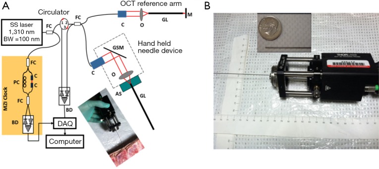
The OCT needle imaging system is similar to the previous reported prototype (see Figure 1A) (30). This frequency-domain OCT system utilizes a wavelength-swept laser as light source which is centered at 1,310 nm with 100 nm bandwidth. The wavelength-swept frequency is 16 kHz with 19 mW output power. A Mach-Zehnder interferometer (MZI) receives 3% of the laser output power and uses it to generate a frequency-clock signal with uniformly spaced optical frequency to trigger the sampling of the OCT signal into data acquisition (DAQ) board. The remaining 97% of the laser power is split evenly into the sample and reference arms of a fiber-based Michelson interferometer. The reflected signals from the sample and reference arms form interference fringes at the fiber coupler (FC). The interference fringes from different depths received by a balanced detector (BD) are encoded with different frequencies. Depth-resolved tomography can be obtained by analyzing the frequency spectrum of the interference fringes through Fourier transform.
Figure 1.

(A) Schematic of the hand-held OCT needle imaging system; (B) hand-held part. The inset image shows the GRIN needle placing aside of a US dime. SS, swept source; BW, bandwidth; MZI, Mach-Zehnder interferometer; FC, fiber coupler; PC, polarization controller; C, collimator; BD, balanced detector; DAQ, data acquisition; M, mirror; GSM, galvonometer scanning mirror; O, objective lens; AS, alignment stage; GL, GRIN lens needle; OCT, optical coherence tomography; GRIN, gradient-index.
During imaging, the laser spot is scanned by a galvonometer scanning mirror (GSM) and delivered into tissues with special relay optics called gradient-index (GRIN) rod lens (31). The GRIN rod lens design eliminates the need to scan in the constrictive distal end and thus significantly reduces the probe size. The axial resolution was optimized with careful dispersion matching at the reference arm using another GRIN rod lens that had the same specifications as the one used in the sample arm. Both the lateral and axial resolutions in tissue are around 13 μm. The needle imaging device is equipped with a 0.5-mm-in-diameter GRIN rod lens, and the resulting lateral imaging field-of-view (FOV) is around 0.44 mm. The sensitivity of system was optimized to 92 dB, calculated using a mirror with a calibrated attenuator. The total outer diameter (O.D.) including the GRIN rod lens and the protective steel tubing is around 0.74 mm, which can be fitted into the clinically-used 18 gauge epidural needle. Figure 1B shows the picture of the miniaturized hand-held needle device. The hand-held portion of this device measures around 13 cm (length) × 4 cm (width) × 4 cm (height), and it enables insertion of the needle device by hand during experiments (see the photo inset in Figure 1A).
Animal imaging experiments
All of the procedures are approved by the Institutional Animal Care and Use Committees (IACUC) at both the University of Maryland and the Children’s National Medical Center (CNMC). For ex vivo tissue imaging, six porcine spinal tissues were purchased from a local slaughter house, and imaged freshly with in several hours after tissue harvest. During imaging, the imaging needle was inserted manually into the tissue. The insertion depth was measured for each recorded image to facilitate the localization of needle tip.
For in vivo experiments, three Yorkshire piglets (~8 kg) were used. The piglets were fasted overnight prior to the day of surgery. The animals were pre-medicated using ketamine (20 mg/kg) and xylazine (2 mg/kg) and weighed. They were then transported to the dedicated animal operating room at CNMC where they were intubated and ventilated, with general anesthesia maintained using isoflurane. The piglet’s neck was pinched with toothed forceps to ensure adequate anesthesia. The piglet’s bilateral groin areas, neck, and lower back was clipped for preparation of procedures. The same areas were then aseptically prepared using Chlorhexidine scrub twice to maintain sterility of the procedure. Upon successful general anesthesia, OCT needle imaging was carried out under sterile condition. During imaging, the animals were monitored continuously using electrocardiograph (ECG) monitoring and pulse oximeter. Vital signs were continuously observed to ensure adequate anesthesia and animal well-being. After experiment, the animals were euthanized compulsorily. Beuthanasia (1 mL per 4.5 lb weight) was administered intravenously into an ear vein. Animal death was determined by listening for heart sounds and respiratory activity. Bilateral thoracotomy was performed as secondary terminal procedure.
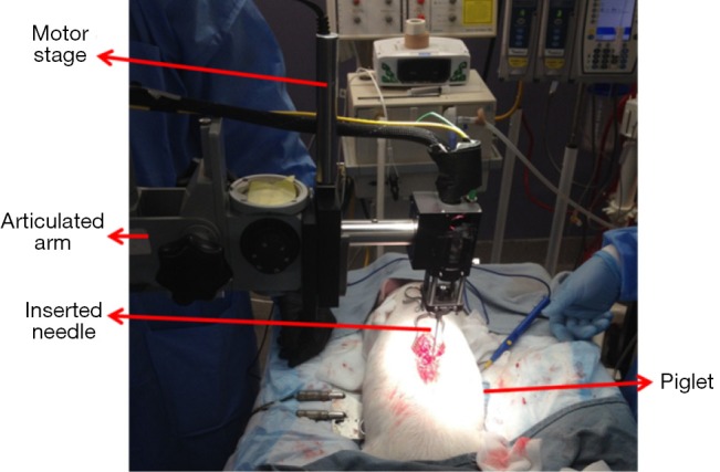
Figure 2 shows the experimental setup for in vivo animal experiments. In order to obtain a smooth insertion process with constant speed and avoid bulk motion due to hand operation, the hand-held part of the OCT needle device was mounted on a motor stage which was controlled by a motor controller (ESP301, 3 Axis Motion Controller, Newport Corporation). The motor stage was fixed on an articulated arm for easy adjustment and stability. During the experiment, the skin of the insertion location was opened and the hand-held needle was slowly inserted into different depths inside the tissue. OCT images were acquired corresponding to different structures during the insertion from the supraspinous ligaments to the spinal cord.
Figure 2.

In vivo piglet experiment setup.
Results and discussion
Ex vivo porcine tissue experiment
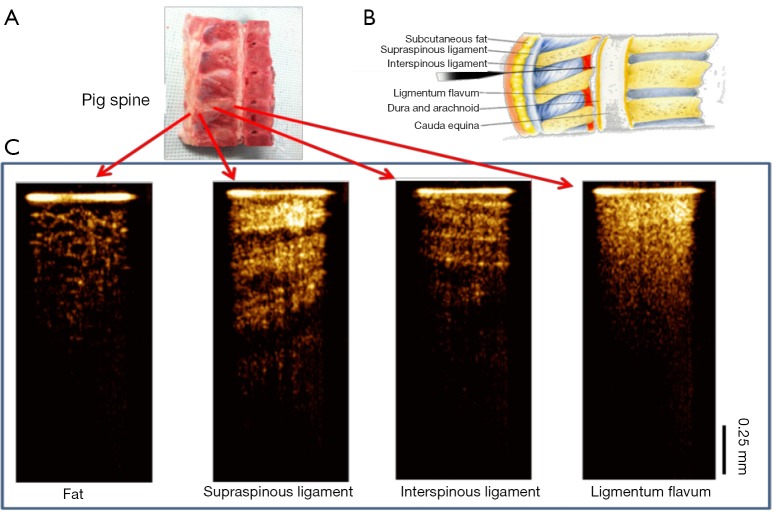
The feasibility of our system for epidural anesthesia guidance was first investigated using an ex vivo porcine spine model. Figure 3 shows representative results of the OCT-guided insertion. Figure 3A shows the photo of the pig spine used for experiment. It was cut in sagittal view and the corresponding structures can be identified based on anatomy as shown in Figure 3B.
Figure 3.
Needle OCT images of spinal tissue ex vivo. (A) The porcine spine tissue used for experiment; (B) anatomy of lumbar spine (sagittal view). Image is adapted from http://pharma-munvar.blogspot.com/2010/02/local-anesthetics-local-anestheticsla.html; (C) cross-sectional OCT images acquired by GRIN needle device corresponding to different tissues. OCT, optical coherence tomography; GRIN, gradient-index.
During experiment, the hand-held needle was slowly inserted into different positions in the tissue. OCT images were acquired corresponding to different structures during the insertion from the skin to the epidural space. The OCT images shown in Figure 3C clearly show different tissue types. The fat tissue is featured with pockets of adipocytes. The ligaments are featured with bright and dark stripes due to birefringence. The supraspinous and interspinous ligaments can be differentiated by their different fiber orientations and thickness of fiber bundles. For ligamentum flavum, its OCT image is bright (hyper-reflective) and homogenous. These results indicate that it is feasible to distinguish epidural space and ligamentum flavum since the epidural space is filled with fat and blood vessels.
In vivo piglet experiment
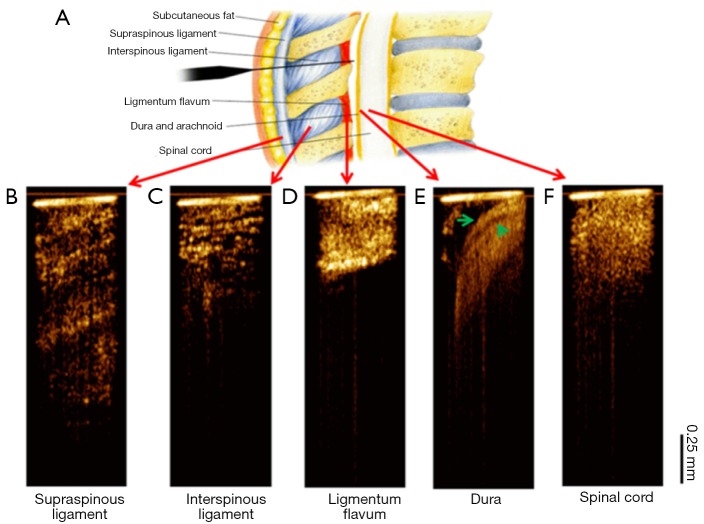
Figure 4 shows the OCT needle images acquired from different tissue types in vivo. Consistent with the ex vivo results, the supraspinous (Figure 4B) and interspinous (Figure 4C) ligaments can be differentiated by their different fiber orientations and thickness of fiber bundles. Furthermore, penetration is much deeper in supraspinous ligaments. The OCT image of ligamentum flavum (Figure 4D) shows bright and homogeneous reflectance. After ligamentum flavum, the probe reached the epidural space (Figure 4E). The dura membrane, a very important landmark for epidural injection, can be identified. The anesthetist can stop the needle here and deliver drugs. Continuing the needle advancement, the needle probe penetrated the dura and reached the spinal cord (Figure 4F). The OCT image of spinal cord shows prominent speckle patterns with the brightness between the dura and ligamentum flavum. These results demonstrate that there are characteristic differences between different structures, especially between ligamentum flavum and dura membrane or fat, which is the landmark for determine the positon of epidural space. The in vivo OCT images clearly show the feasibility of differentiating tissue types in real time, therefore, it will be beneficial to guide the anesthetists to identify the needle tip location during epidural interventions.
Figure 4.
In vivo needle optical coherence tomography (OCT)-guided insertion. (A) Tissue layers through epidural needle insertion track. Image is adapted from http://pharma-munvar.blogspot.com/2010/02/local-anesthetics-local-anestheticsla.html; (B-F) in vivo needle OCT images corresponding to different tissues types: supraspinous (B) and interspinous (C) ligaments, ligamentum flavum (D), epidural space (E) with the dura membrane indicated by two green arrows, and spinal cord (F). The bright horizontal line at the top of each OCT image indicates the tip of needle.
Conclusions
We have developed an OCT forward-imaging needle device which can be integrated with an 18-gauge epidural needle and acquires OCT images in real-time for epidural anesthesia surgery guidance. The ability to identify tissues at different locations along the insertion to epidural space was demonstrated both ex vivo and in vivo. More in vivo experiments on animal models are necessary to further assess this device’s potential to improve the rate of successful epidural anesthesia. In addition, we are in the process of developing quantitative imaging parameters such as tissue attenuation and texture for better classification of tissue types. With relevant tissue structures clearly visualized and differentiated at the needle tip, the OCT needle imaging device is promising to enhance clinical outcomes with regards to complication rates, induced pain, and procedure failure when compared to standard practice. Furthermore, this technology could be used in combination with ultrasound/fluoroscopy to further enhance the clinical outcomes.
Acknowledgements
We would like to thank the support from UMCP-CNMC Seed Grant Program.
Disclosure: The authors declare no conflict of interest.
References
- 1.Heran MK, Smith AD, Legiehn GM. Spinal injection procedures: a review of concepts, controversies, and complications. Radiol Clin North Am 2008;46:487-514, v-vi. [DOI] [PubMed] [Google Scholar]
- 2.Scott DB. Identification of the epidural space: loss of resistance to air or saline? Reg Anesth 1997;22:1-2. [DOI] [PubMed] [Google Scholar]
- 3.Rathmell JP, Desjardins AE, van der Voort M, Hendriks BH, Nachabe R, Roggeveen S, Babic D, Söderman M, Brynolf M, Holmström B. Identification of the epidural space with optical spectroscopy: an in vivo swine study. Anesthesiology 2010;113:1406-18. [DOI] [PubMed] [Google Scholar]
- 4.Grau T, Leipold RW, Conradi R, Martin E, Motsch J. Efficacy of ultrasound imaging in obstetric epidural anesthesia. J Clin Anesth 2002;14:169-75. [DOI] [PubMed] [Google Scholar]
- 5.Jeng CL, Torrillo TM, Rosenblatt MA. Complications of peripheral nerve blocks. Br J Anaesth 2010;105Suppl 1:i97-107. [DOI] [PubMed] [Google Scholar]
- 6.Curatolo M, Orlando A, Zbinden AM, Scaramozzino P, Venuti FS. A multifactorial analysis to explain inadequate surgical analgesia after extradural block. Br J Anaesth 1995;75:274-81. [DOI] [PubMed] [Google Scholar]
- 7.Rigg JR, Jamrozik K, Myles PS, Silbert BS, Peyton PJ, Parsons RW, Collins KS, MASTER Anaethesia Trial Study Group . Epidural anaesthesia and analgesia and outcome of major surgery: a randomised trial. Lancet 2002;359:1276-82. [DOI] [PubMed] [Google Scholar]
- 8.Ho KY. Vascular uptake of contrast despite negative aspiration in interlaminar cervical epidural injection. Pain Physician 2006;9:267-8. [PubMed] [Google Scholar]
- 9.Hodges SD, Castleberg RL, Miller T, Ward R, Thornburg C. Cervical epidural steroid injection with intrinsic spinal cord damage. Two case reports. Spine (Phila Pa 1976) 1998;23:2137-42; discussion 2141-2. [DOI] [PubMed] [Google Scholar]
- 10.Tripathi M, Nath SS, Gupta RK. Paraplegia after intracord injection during attempted epidural steroid injection in an awake-patient. Anesth Analg 2005;101:1209-11. [DOI] [PubMed] [Google Scholar]
- 11.Saberski LR, Kondamuri S, Osinubi OY. Identification of the epidural space: is loss of resistance to air a safe technique? A review of the complications related to the use of air. Reg Anesth 1997;22:3-15. [DOI] [PubMed] [Google Scholar]
- 12.Grondin LS, Nelson K, Ross V, Aponte O, Lee S, Pan PH. Success of spinal and epidural labor analgesia: comparison of loss of resistance technique using air versus saline in combined spinal-epidural labor analgesia technique. Anesthesiology 2009;111:165-72. [DOI] [PubMed] [Google Scholar]
- 13.Evron S, Sessler D, Sadan O, Boaz M, Glezerman M, Ezri T.Identification of the epidural space: loss of resistance with air, lidocaine, or the combination of air and lidocaine. Anesth Analg 2004;99:245-50. [DOI] [PubMed] [Google Scholar]
- 14.McLeod A, Roche A, Fennelly M.Case series: Ultrasonography may assist epidural insertion in scoliosis patients. Can J Anaesth 2005;52:717-20. [DOI] [PubMed] [Google Scholar]
- 15.Stojanovic MP, Vu TN, Caneris O, Slezak J, Cohen SP, Sang CN. The role of fluoroscopy in cervical epidural steroid injections: an analysis of contrast dispersal patterns. Spine (Phila Pa 1976) 2002;27:509-14. [DOI] [PubMed] [Google Scholar]
- 16.Ting CK, Tsou MY, Chen PT, Chang KY, Mandell MS, Chan KH, Chang Y. A new technique to assist epidural needle placement: fiberoptic-guided insertion using two wavelengths. Anesthesiology 2010;112:1128-35. [DOI] [PubMed] [Google Scholar]
- 17.Richardson J, Groen GJ. Applied epidural anatomy. Contin Educ Anaesth Crit Care Pain 2005;5:98-100. [Google Scholar]
- 18.Ting CK, Chang Y. Technique of fiber optics used to localize epidural space in piglets. Opt Express 2010;18:11138-47. [DOI] [PubMed] [Google Scholar]
- 19.Gong CS, Lin SP, Mandell MS, Tsou MY, Chang Y, Ting CK. Portable optical epidural needle-a CMOS-based system solution and its circuit design. PLoS One 2014;9:e106055. [DOI] [PMC free article] [PubMed] [Google Scholar]
- 20.Lin SP, Mandell MS, Chang Y, Chen PT, Tsou MY, Chan KH, Ting CK. Discriminant analysis for anaesthetic decision-making: an intelligent recognition system for epidural needle insertion. Br J Anaesth 2012;108:302-7. [DOI] [PubMed] [Google Scholar]
- 21.Desjardins AE, Hendriks BH, van der Voort M, Nachabé R, Bierhoff W, Braun G, Babic D, Rathmell JP, Holmin S, Söderman M, Holmström B. Epidural needle with embedded optical fibers for spectroscopic differentiation of tissue: ex vivo feasibility study. Biomed Opt Express 2011;2:1452-61. [DOI] [PMC free article] [PubMed] [Google Scholar]
- 22.Huang D, Swanson EA, Lin CP, Schuman JS, Stinson WG, Chang W, Hee MR, Flotte T, Gregory K, Puliafito CA, Fujimoto JG. Optical coherence tomography. Science 1991;254:1178-81. [DOI] [PMC free article] [PubMed] [Google Scholar]
- 23.Bouma BE, Tearney GJ. Clinical imaging with optical coherence tomography. Acad Radiol 2002;9:942-53. [DOI] [PubMed] [Google Scholar]
- 24.Li XD, Boppart SA, Van Dam J, Mashimo H, Mutinga M, Drexler W, Klein M, Pitris C, Krinsky ML, Brezinski ME, Fujimoto JG. Optical coherence tomography: advanced technology for the endoscopic imaging of Barrett’s esophagus. Endoscopy 2000;32:921-30. [DOI] [PubMed] [Google Scholar]
- 25.Wang RK. Optical Microangiography: A Label Free 3D Imaging Technology to Visualize and Quantify Blood Circulations within Tissue Beds in vivo. IEEE J Sel Top Quantum Electron 2010;16:545-54. [DOI] [PMC free article] [PubMed] [Google Scholar]
- 26.Chen Z, Milner TE, Dave D, Nelson JS. Optical Doppler tomographic imaging of fluid flow velocity in highly scattering media. Opt Lett 1997;22:64-6. [DOI] [PubMed] [Google Scholar]
- 27.Raphael DT, Yang C, Tresser N, Wu J, Zhang Y, Rever L. Images of spinal nerves and adjacent structures with optical coherence tomography: preliminary animal studies. J Pain 2007;8:767-73. [DOI] [PubMed] [Google Scholar]
- 28.Li X, Chudoba C, Ko T, Pitris C, Fujimoto JG. Imaging needle for optical coherence tomography. Opt Lett 2000;25:1520-2. [DOI] [PubMed] [Google Scholar]
- 29.Han S, Sarunic MV, Wu J, Humayun M, Yang C. Handheld forward-imaging needle endoscope for ophthalmic optical coherence tomography inspection. J Biomed Opt 2008;13:020505. [DOI] [PubMed] [Google Scholar]
- 30.Liang CP, Wierwille J, Moreira T, Schwartzbauer G, Jafri MS, Tang CM, Chen Y. A forward-imaging needle-type OCT probe for image guided stereotactic procedures. Opt Express 2011;19:26283-94. [DOI] [PMC free article] [PubMed] [Google Scholar]
- 31.Xie T, Guo S, Chen Z, Mukai D, Brenner M.GRIN lens rod based probe for endoscopic spectral domain optical coherence tomography with fast dynamic focus tracking. Opt Express 2006;14:3238-46. [DOI] [PubMed] [Google Scholar]


