Abstract
An on-chip actuation transmitter for achieving fast and accurate cell manipulation is proposed. Instead of manipulating cell position by a directly connected macro-scale pump, polydimethylsiloxane deformation is used as a medium to transmit the actuation generated from the pump to control the cell position. This actuation transmitter has three main advantages. First, the dynamic response of cell manipulation is faster than the conventional method with direct flow control based on both the theoretical modeling and experimental results. The cell can be manipulated in a simple harmonic motion up to 130 Hz by the proposed actuation transmitter as opposed to 90 Hz by direct flow control. Second, there is no need to fill the syringe pump with the sample solution because the actuation transmitter physically separates the fluids between the pump and the cell flow, and consequently, only a very small quantity of the sample is required (<1 μl). In addition, such fluid separation makes it easy to keep the experiment platform sterilized because there is no direct fluid exchange between the sample and fluid inside the pump. Third, the fabrication process is simple because of the single-layer design, making it convenient to implement the actuation transmitter in different microfluidic applications. The proposed actuation transmitter is implemented in a lab-on-a-chip system for red blood cell (RBC) evaluation, where the extensibility of red blood cells is evaluated by manipulating the cells through a constriction channel at a constant velocity. The application shows a successful example of implementing the proposed transmitter.
I. INTRODUCTION
Microfluidic techniques have been widely used in biomechanical and biochemical research in the last decade because of their capability for single cell manipulation and evaluation. For example, studies have been conducted on finding the biomarkers of cancer cells,1–4 and evaluating the deformability of human red blood cells (RBCs).5–8 To provide consistent operation and evaluation in microfluidic devices, the control of cell motion is essential. There are four main approaches to cell manipulation: optical, magnetic, electric, and mechanical.9–13 Of these, the mechanical approach of hydrodynamics is usually used for applications with large numbers of cells, or cells requiring fast manipulation because it is capable of driving the whole flow in a microfluidic device. In the mechanical approach of hydrodynamics, the cell motion is usually assumed to be moving with the flow of the suspension fluid, because of its low Reynolds number.14 Unger et al. published one of the earliest studies using polydimethylsiloxane (PDMS) deformation for controlling flow in a two-layer microfluidic device.15 Subsequently, PDMS deformation has been applied to flow control for different purposes. For example, Gong et al. proposed a hand-powered membrane pump for a patient-to-chip syringe interface.16 Davies et al. developed a microthrottle pump for pumping whole blood.17 Sakuma et al. used PDMS deformation to achieve cell manipulation by direct flow control.18 The proposed actuation transmitter in this study also uses such PDMS deformation as the core of its transmission, and in addition, a high-speed piezoelectric actuator and a high-speed camera are equipped in this system to achieve high-speed cell manipulation. To the best of the authors' knowledge, this is the first work that investigates the frequency response of cell manipulation using an actuation transmitter based on PDMS deformation.
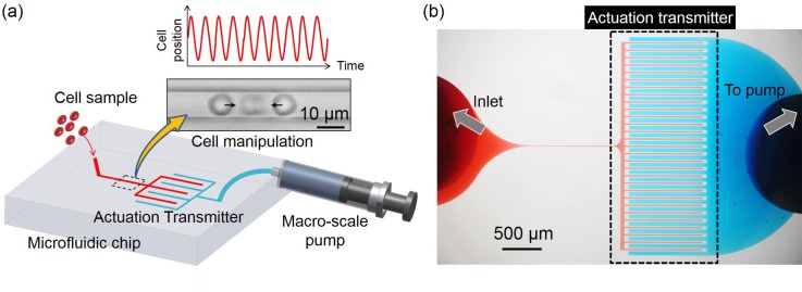
Figs. 1(a) and 1(b) show the illustration of the proposed actuation transmitter system, and a photograph taken through a microscope of the actual fabricated microfluidic system. In the proposed actuation transmitter shown in Fig. 1(a), two physically separated microfluidic circuits are made on the same layer of a microfluidic chip, and are the circuits for cell manipulation and actuation, shown as the red and blue circuits, respectively. The cells are put into the device from the inlet of the manipulation circuit while the inlet of the actuation circuit is connected to a macro-scale pump controlled by a piezoelectric actuator. The cell position is indirectly manipulated by the macro-scale pump through the actuation transmitter with a real-time feedback controller, using the cell position from a high-speed camera.
FIG. 1.
The overview of the proposed actuation transmitter. (a) Samples are injected into the chip from the left inlet into the manipulation circuit (red) and manipulated by the separated control circuit (blue) through the actuation transmitter. (b) A photograph of the actual microfluidic system where the two circuits are filled with different color dyes for identification.
The manipulation system with and without the proposed actuation transmitter is investigated through theoretical modeling and experiments. The system is modelled by a mechanical system and its response shows that the time constant is shortened with the proposed transmitter. In the experiments, the RBCs are manipulated in simple harmonic motion (SHM) at different frequencies. The theoretical results confirmed that the frequency response of RBC manipulation with the proposed actuation transmitter was better than without it. The phase angle between the target position and actual RBC position reached 180° while RBCs were manipulated at 90 Hz without the actuation transmitter, but can be manipulated up to 130 Hz with it. The experimental results show that the cell manipulation with the proposed actuation transmitter can not only achieve the same accurate manipulation without the actuation transmitter as in our former work6,18 but also performs better in terms of frequency response. An integrated microfluidic system with the proposed actuation transmitter was developed as an example of an application, and the extensibility of RBCs from the same subject was evaluated. The actuation transmitter manipulated the RBCs through a constriction channel at a constant velocity successfully, even when the RBCs were significantly deformed.
The remainder of the paper is organized as follows. The working principle of the proposed actuation transmitter along with theoretical modeling is presented in Sec. II. Computational simulation for the transmission with different dimensions of transmitter designs is performed in Sec. III. The experimental design, setup, procedure, and results for cell manipulation with and without the proposed actuation transmitter are outlined in Sec. IV. An example of employing the proposed actuation transmitter in an integrated evaluation system and the evaluation results are shown in Sec. V. Finally, the paper is concluded in Sec. VI.
II. WORKING PRINCIPLE AND MODELING
A. Deformation transmission between two separated microfluidic circuits
Fig. 2 illustrates the working principle of the proposed actuation transmitter where the red and blue blocks represent the microfluidic circuits for cell manipulation and actuation, respectively. Fig. 2(a) shows the neutral state where no external pressure is applied from the macro-scale pump. When the pump pushes forward, the pressure in the actuation circuit increases and leads to the deformation as shown in Fig. 2(b). The deformation of the right circuit transmits to the left-hand circuit through PDMS deformation, and causes a drop in pressure on the right-hand side of the manipulation circuit. As a result, the RBC is moved to the right as indicated by the red arrow. Conversely, if the pump were retracted backwards by the actuator, as shown in Fig. 2(c), the RBC would move to the left. In summary, the actuation from the macro-scale pump is transmitted through PDMS deformation while the direction of actuation is reversed.
FIG. 2.

The working principle of the actuation transmitter. (a) At neutral state, the microfluidic channels are not deformed. (b) When the macro-scale pump pushes forward, RBC moves to the right. (c) When the macro-scale pump is retracted backward, the RBC moves to the left.
B. Dynamic response of cell manipulation with the actuation transmitter
The relationship between the movement of a macro-scale pump and a micro-scale cell displacement without the transmitter was discussed with the mechanical model as shown in Fig. 3(a).18 To understand the system with the proposed transmitter, we adopted and extended the model with additional components representing the transmitter, the highlighted area in Fig. 3(b). The deformations of PDMS at different parts of the system are represented by equivalent components of a piston and a spring. The deformation is said to be the same as the volume change caused by the piston movement, and the structural stiffness of the parts are represented by spring constant . and are the cross-sectional area and displacement of the pistons, respectively. The subscripts 1, 2, 3, 4, and indicate the piston-spring sets of the macro-scale pump and the deformations of the transmitter on the actuation side, the actuation circuit and the transmitter on the manipulation side, as illustrated in Fig. 3(b). Assuming that the fluid inside the microfluidic circuits is incompressible, the constant volumetric flow in the circuits gives
| (1) |
| (2) |
We assume the flow is laminar, thus can also describe the cell displacement. Conversely, the force balance of the system gives
| (3) |
| (4) |
| (5) |
where and are the pressure in the actuation circuit, the pressure in the manipulation circuit, and the viscosity of the fluid in the circuit, respectively. We assume the fluid flow inside the manipulation circuit is laminar, thus the fluid flow can also represent the velocity of the manipulated cell. The transfer function is defined as , which shows the relationship between cell displacement and pump displacement. The general solution of can be derived from Eqs. (1) to (5), and is
where
| (6) |
where is the time constant of the response of the system in Fig. 3(b). Let be the time constant in the manipulation system without any transmitter as in Fig. 3(a),18 and we have the relationship between the two time constants as
| (7) |
We can further simplify the relationship by assuming . Equation (8) then becomes
| (8) |
in Eq. (8) is the ratio between two time constants, and is always smaller than one when and . The results show that the time constant of the system with the proposed actuation transmitter is shortened by implementing the transmitter. In other words, the dynamic response of the system should be enhanced because of the additional stiffness term brought to the system with the actuation transmitter.
FIG. 3.

A mechanical model for cell motion and manipulation. (a) The model of a conventional manipulation system without an actuation transmitter where a macro-scale pump directly controls the cell motion. Reprinted with permission from Sakuma et al., Micromachines 5, 1188–1201 (2014). Copyright 2014 MDPI Creative Commons Attribution 4.0 International. (b) The manipulation system where cell motion is controlled by a macro-scale pump through the proposed actuation transmitter.
To understand the physical meaning behind the results in Eqs. (6) and (8), two extreme cases are discussed here. The first extreme case is when the stiffness term of the actuation transmitter, , is extremely small as in , will be obtained in Eq. (8). Physically, this means that the actuation from the macro-scale pump is fully transmitted through an extremely soft transmitter, so that the time constant is the same as with the system without the transmitter. In contrast, when the transmitter becomes very stiff, as in , the ratio of the time constants becomes zero, which shows that the response of the system with the transmitter is very much faster than without the transmitter. However, the magnitude of the output in Eq. (6) would also turn zero, as in , meaning no actuation will be transmitted because the transmitter is too stiff to deform. Such characteristics show the limitation of the system with the proposed transmitter when the gain of actuation is limited by from the transmitter. In other words, the gain of the system is a tradeoff against the enhanced dynamic response according to the model in Fig. 3(b). We specifically note that the effect of inertia in the system was ignored in this simplified model, and the derived response was only valid for the simplified model shown in Fig. 3(b).
III. COMPUTATIONAL SIMULATION
Computational simulation is performed in this section to determine a proper set of dimensions for the transmitter design. Fig. 4(a) shows the design of the actuation transmitter used for the experiments. The coupled comb-shaped design works on the same principle as that discussed in Sec. II, except for the shape and geometry. The comb-like shape increases the mutual interaction between the circuits for actuation and manipulation to achieve a better transmission.
FIG. 4.
The simulation results for three different widths of subchannels on the actuation side of the actuation transmitter circuit. (a) The design of the actuation transmitter in a 3D view. (b) The deformation on the cross-sections of the actuation transmitter is shown by different colors. The cross-sections are as the AA′ cross-section in (a). (c) The increase in area of the subchannels on the manipulation side resulting from the deformation with different subchannel widths is obtained from the simulation with respect to different pressures.
The simulation was performed using COMSOL Multiphysics® (version 4.0a, COMSOL), using the finite element method for computing the deformation of the actuation transmitter circuits on both the actuation and the manipulation sides. The Young's modulus, Poisson ratio, and density of the PDMS are set as kPa, , and , respectively. These parameters correspond to the PDMS with a mixing volume ratio of 1:10 as the curing agent versus polymer.19 The bottom of the microfluidic chip is assumed rigid and the bonding between the PDMS and substrate is assumed to be firmly attached. Geometrical parameters for the simulations are given as μm, μm, and μm, where , , and are the width of each subchannel on the manipulation circuit side of the actuation transmitter, the height of both the subchannels and the distance between subchannels, respectively. Three different widths for the actuation subchannels are simulated, while the other parameters are kept constant.
Fig. 4(b) shows the simulation results under a given fluidic pressure in the actuation subchannels kPa, where three results from top to bottom are with μm, respectively. Different colors indicate different levels of deformation for each color bar on the left. For example, the area in dark blue shows zero deformation while and dark red shows μm displacement for the top result in Fig. 4(b). The cross-sectional areas in Fig. 4(b) correspond to AA′ in Fig. 4(a). According to the graphical results, we find that a greater deformation of both the circuits for the manipulation and actuation is obtained with a wider subchannel width.
Fig. 4(c) shows the deformation of the area change, , of each cross section on the manipulation side of the actuation transmitter with respect to different given pressures, , on the actuation side of the actuation transmitter. Green, red, and blue lines in Fig. 4(c) are the results with μm, respectively. According to the simulation results, μm gives the greatest as well as best sensitivity in terms of transmitter deformation for the same given pressure; therefore, is used for this experimental study.
IV. EXPERIMENTS
A. Experimental setup
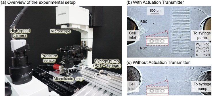
Fig. 5(a) shows an overview of the experimental system, which is composed of a microfluidic chip, syringe pump, high-speed camera, pressure sensor, and microscope. The image resolution of the high-speed camera (Photron Co.) and the microscope (IX71, Olympus Co.) is 240 nm/pixel while the frame rate of the camera is set at 1000 frames per second (fps). The syringe pump is bolted to the piezoelectric actuator (Messtech Co.) to minimize any possible backlash during syringe retraction. The microfluidic chip is a single-layer design fabricated using PDMS with a standard soft-lithography process. The volume ratio of the curing agent and polymer for the PDMS is 1:10, which is the same as the ratio used in the simulation in Sec. III. Figs. 5(b) and 5(c) show the photos taken during the experiments, and are the cell manipulation chips with and without the proposed actuation transmitter circuit, respectively. The RBCs are put into the manipulation circuit from the inlet on the left while the syringe pump is directly connected to the inlet on the right. The RBCs are taken from a volunteer subject, who read and signed the consent for the experiment. The black particles in Figs. 5(b) and 5(c) are the RBCs.
FIG. 5.
The experimental system. (a) A photograph of the experimental system which is constructed using a microfluidic chip, syringe pump, high-speed camera, microscope, and pressure sensor. (b) A photograph of the manipulation system with the actuation transmitter in action, where the black objects are RBCs. (c) A photograph of the manipulation system without the actuation transmitter. RBCs are manipulated with the same pressure at the sample inlet for both cases.
The manipulation system was developed on a proportional-integral-derivative (PID) controller with visual feedback of cell position and programmable piezoelectric actuator. RBCs are manipulated by the controller to follow an assigned target position. The target position follows a SHM signal with different frequencies. The RBC is first manipulated at 1 Hz and the frequency is gradually increased until the phase lag between the target position and measured RBC position reaches , which indicates the frequency limit of the manipulation system. For each frequency, at least five different RBCs are tested to ensure system performance.
To compare the performance of cell manipulation with and without an actuation transmitter, the same experiments are repeated on both chips shown in Figs. 5(b) and 5(c), and the conditions, such as channel dimensions and fluid pressure at the cell inlets, are kept the same for both systems. The dimensions of the actuation transmitter are μm, where is the length of each subchannel. The number of paired subchannels of the transmitter is 30.
B. Experimental results
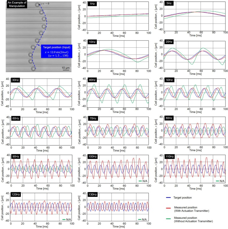
Fig. 6 shows the experimental results of manipulating RBCs in SHM at different frequencies (see Ref. 20 for supplementary material). Overall, fifteen different frequencies, are performed in the experiments and the input target position for the manipulation is calculated using the following equation:
| (9) |
where , , and are the input target position, frequency of SHM and elapsed time, respectively. The magnitude of 12 μm in Eq. (9) is equivalent to 50 pixels on the images from the high-speed camera.
FIG. 6.
The experimental results of manipulating RBCs with and without the actuation transmitter in SHM. The plots of cell position during the manipulation are at 1, 5, 10, 20, 30 40, 50, 60, 70, 80, 90. 100, 110, 120, and 130 Hz.
The top-left corner of Fig. 6 shows an example of a cell being manipulated along given target positions in a series of photographs, and the remainder show the results of the target position (blue) and cell positions with/without actuation transmitter (red/green) at frequencies from 1 to 130 Hz. The responses of cell position without the transmission are not applicable after 90 Hz because the phase lag reaches at 90 Hz and cell motion diverges beyond that. The results show that even at the lowest frequency such as 1 Hz, the manipulation without the actuation transmitter is slightly behind the input target positions. Conversely, the manipulation system with the actuation transmitter is clearly better in terms of phase lag, which remains less than until .
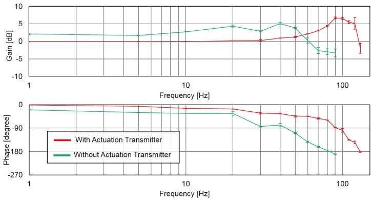
The data for the measured cell position and time are inserted into discrete Fourier transforms for calculating the phase angle and gain of the RBC manipulation with respect to the given target positions. Fig. 7 shows the frequency responses with (red) and without (green) the proposed actuation transmitter. The test at each frequency is repeated at least five times with different target cells, and the standard deviation from test to test is represented by the error bar in Fig. 7. The results show that the manipulation system with the actuation transmitter is better than the conventional method without an actuation transmitter on phase lag. The quicker response from the experimental results is well matched to the response derived in Sec. II.
FIG. 7.
The frequency response of cell manipulation with and without the actuation transmitter.
V. AN APPLICATION FOR EVALUATING RBC EXTENSIBILITY
One of the goals of microfluidic research is to develop an all-in-one microfluidic chip to perform a simple and easy evaluation or diagnosis.21 To achieve this goal, different microfluidic functions must be implemented on a single chip. The actuation transmitter proposed in this study can be easily implemented on a single chip because the actuation transmitter is built with a single-layer design. As an example of an application, we put the proposed actuation transmitter and different functional microfluidic systems on a lab-on-a-chip system for evaluating RBC extensibility from whole blood. The RBC extensibility was previously found to be related to cell fatigue state, which is defined as the ability of a RBC to recover from reciprocated mechanical stress.6 Furthermore, the required quantity for the sample was expected to be less than 1 μl for the total volume of the evaluation circuit.
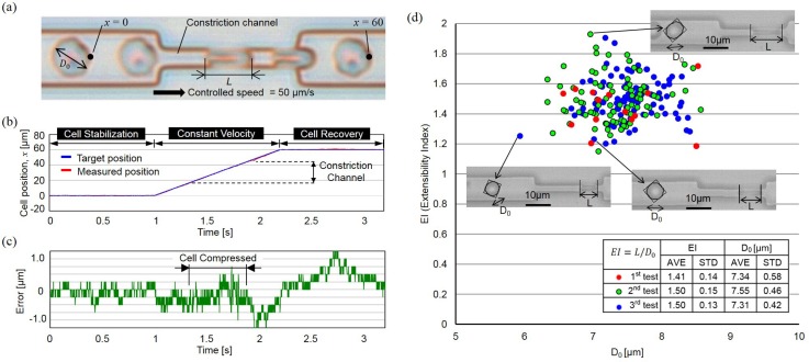
The operation flow of the evaluation and the design of the microfluidic system are illustrated in Figs. 8(a) and 8(b). The integrated chip consists of three main parts, the parts for on-chip dilution, extensibility evaluation, and the actuation transmitter. The flow of operation, after a small quantity of blood is retrieved from a subject, is for the blood to be directly inserted into the chip from the inlet for on-chip RBC dilution. The purpose of dilution is to reduce the number of RBCs to make single cell manipulation possible while avoiding using any artificial buffer solution. Next, the RBCs are evaluated using the evaluation circuit. Each target RBC is first held steady in front of the constriction channel for 2 s, so that its undeformed size can be measured without the influence of shear stress from fluid flow. The diameter of the undeformed RBC, , is used as the basis for calculating cell extensibility. After measuring the undeformed diameter, , each RBC is manipulated through the constriction channel at a constant velocity of 50 μm/s using the cell manipulation system with the proposed actuation transmitter (see Ref. 20 for supplementary material). The length of deformed the RBC, L, is measured during the transit inside the constriction channel. To evaluate deformability, we define the extensibility as . The has previously been discovered to be directly related to the state of cell fatigue.6 In addition, the minimal required quantity of the sample for the test, whole blood in this case, is less than 1 μl. The volume is calculated based on the microfluidic design using the commercial software Autocad (Autodesk, Inc.), and the volume required for fully filling the evaluation circuit is μl with a total surface area of 7.3 mm2 and a circuit height of 0.0035 mm. The volume is significantly reduced compared to our former systems6 because of the physical separation of the evaluation circuit and actuation circuit using the proposed actuation transmitter.
FIG. 8.
An application of the actuation transmitter. The transmitter is embedded in an integrated chip for RBC extensibility evaluation. (a) Whole blood is directly inserted into the chip for the evaluation. (b) The integrated lab-on-chip system includes the parts of dilution (red), evaluation (blue), and the actuation transmitter (green) as the three highlighted blocks.
The throughput of the system depends on the duration of the measurement, the transit time under the specified velocity and the speed of cell feed. In this particular case, the time for testing one cell was 3.2 s, including 2 s for the measurement and 1.2 s transit time at the constant velocity. However, the actual feeding speed depends on the on-chip dilution part, and has a wide variation, which can be as short as few milliseconds or as long as tens of seconds. By assuming the cells are constantly fed to the evaluation part every 6 s, the throughput of the system can be estimated at about 6.5 cells/min.
The RBC extensibility of the same subject was evaluated three times on three different days, and the results are summarized in Fig. 9. Fig. 9(a) shows a series of RBC motions through the constriction channel. Figs. 9(b) and 9(c) show the position of an RBC and the error from the input target position, respectively. The error is within 1.2 μm even during the transit of RBCs through the constriction channel where they are heavily deformed. Fig. 9(d) shows the evaluation results of the relationship between EI and for the subject. Examples of RBC photographs captured from the experiment are shown for selected points. Each image in Fig. 9(d) is the combination of two separate images, the images when the cell is held steady for the measurement and when the cell is moved at constant velocity through the constriction channel. In summary, preliminary results for the RBC extensibility were acquired using the integrated microfluidic chip, and it supports the feasibility of applying the proposed actuation transmitter in a microfluidic application for accurate cell manipulation.
FIG. 9.
RBCs are controlled passing through the constriction channel at constant speed using the proposed actuation transmitter for the evaluation. (a) Snapshots of a RBC moving through the constriction channel. (b) and (c) The tracked cell position and the errors from the input target position. (d) The evaluation results for the extensibility of the tested RBCs.
VI. CONCLUSIONS
A microfluidic actuation transmitter is proposed and was experimentally tested in this study. The concluding remarks are:
-
(1)
According to the theoretical modeling and experimental results, the dynamic response of cell manipulation with the actuation transmitter was better than the manipulation without the actuation transmitter. The actuation transmitter has experimentally shown its capability of manipulating a cell in a SHM up to 130 Hz.
-
(2)
The tradeoff for enhanced dynamic response is that the gain of actuation is limited by the elastomeric property of the transmitter. Thus, the proposed actuation transmitter is suitable for fast cell manipulation under low magnitude.
-
(3)
The actuation transmitter physically separates the actuation and cell manipulation circuits, which avoids filling the connected macro-scale pump with the sample solution and is desirable for keeping the experimental platform sterilized as well as suitable for the testing with small sample quantities.
-
(4)
The actuation transmitter was designed on a single layer and can be easily implemented on different microfluidic applications. The actuation transmitter was successfully implemented to a lab-on-a-chip system for extensibility evaluation.
ACKNOWLEDGMENTS
This work was supported by Grant Nos. 23106003, 26630098, and 26820086 and “Creating Hybrid Organs of the future” for The Ministry of Education, Culture, Sports, Science and Technology (MEXT) of Japan.
References
- 1.Huang Y., Agrawal B., Sun D., Kuo J. S., and Williams J. C., Biomicrofluidics 5, 013412 (2011). 10.1063/1.3555195 [DOI] [PMC free article] [PubMed] [Google Scholar]
- 2.Zhang Z., Xu J., Hong B., and Chen X., Lab Chip 14, 2576–2584 (2014). 10.1039/c4lc00301b [DOI] [PubMed] [Google Scholar]
- 3.Lin Y.-H., Chen Y.-J., Lai C.-S., Chen Y.-T., Chen C.-L., Yu J.-S., and Chang Y.-S., Biomicrofluidics 7, 024103 (2013). 10.1063/1.4794974 [DOI] [PMC free article] [PubMed] [Google Scholar]
- 4.Byun S., Son S., Amodei D., Cermak N., Shawa J., Kang J. H., Hecht V. C., Winslow M. M., Jacks T., Mallick P., and Manalis S. R., PNAS 110(19), 7580–7585 (2013). 10.1073/pnas.1218806110 [DOI] [PMC free article] [PubMed] [Google Scholar]
- 5.Tsai C. D., Sakuma S., Arai F., and Kaneko M., RSC Adv. 4(85), 45050–45058 (2014). 10.1039/C4RA08276A [DOI] [Google Scholar]
- 6.Sakuma S., Kuroda K., Tsai C. D., Fukui W., Arai F., and Kaneko M., Lab Chip 14, 1135–1141 (2014). 10.1039/c3lc51003d [DOI] [PubMed] [Google Scholar]
- 7.Tomaiuolo G., Barra M., Preziosi V., Cassinese A., Rotoli B., and Guido S., Lab Chip 11, 449–454 (2011). 10.1039/c0lc00348d [DOI] [PubMed] [Google Scholar]
- 8.Tsai C. D., Sakuma S., Arai F., and Kaneko M., IEEE Trans. Biomed. Eng. 61(4), 1187–1195 (2014). 10.1109/TBME.2013.2296624 [DOI] [PubMed] [Google Scholar]
- 9.Yun H., Kim K., and Lee W. G., Biofabrication 5, 022001 (2013). 10.1088/1758-5082/5/2/022001 [DOI] [PubMed] [Google Scholar]
- 10.Huang N.-T., Zhang H., Chung M.-T., Seo J. H., and Kurabayashi K., Lab Chip 14, 1230–1245 (2014). 10.1039/c3lc51211h [DOI] [PubMed] [Google Scholar]
- 11.Liu Y.-J., Guo S.-S., Zhang Z.-L., Huang W.-H., Baigl D., Xie M., Chen Y., and Pang D.-W., Electrophoresis 28, 4713–4722 (2007). 10.1002/elps.200700212 [DOI] [PubMed] [Google Scholar]
- 12.Doh I. and Cho Y.-H., Sens. Actuators A 121, 59–65 (2005). 10.1016/j.sna.2005.01.030 [DOI] [Google Scholar]
- 13.Hur S. C., Henderson-MacLennan N. K., McCabe E. R. B., and Carlo D. D., Lab Chip 11, 912–920 (2011). 10.1039/c0lc00595a [DOI] [PubMed] [Google Scholar]
- 14.Sugii Y., Okuda R., Okamoto K., and Madarame H., Meas. Sci. Technol. 16, 1126–1130 (2005). 10.1088/0957-0233/16/5/011 [DOI] [Google Scholar]
- 15.Unger M. A., Chou H. P., Thorsen T., Scherer A., and Quake S. R., Science 288, 113–116 (2000). 10.1126/science.288.5463.113 [DOI] [PubMed] [Google Scholar]
- 16.Gong M. M., MacDonald B. D., Nguyen T. V., and Sinton D., Biomicrofluidics 6, 44102 (2012). 10.1063/1.4762851 [DOI] [PMC free article] [PubMed] [Google Scholar]
- 17.Davies M. J., Johnston I. D., Tan C. K. L., and Tracey M. C., Biomicrofluidics 4, 044112 (2010). 10.1063/1.3528327 [DOI] [PMC free article] [PubMed] [Google Scholar]
- 18.Sakuma S., Kuroda K., Arai F., Taniguchi T., Ohtani T., Sakata Y., and Kaneko M., Micromachines 5(4), 1188–1201 (2014). 10.3390/mi5041188 [DOI] [Google Scholar]
- 19.Armani D., Liu C., and Aluru N., in Twelfth IEEE International Conference on Micro Electro Mechanical Systems (MEMS '99), Orlando, FL ( IEEE, 1999), pp. 222–227. [Google Scholar]
- 20.See supplementary material at http://dx.doi.org/10.1063/1.4907757E-BIOMGB-9-016501 for the manipulation of a RBC in simple harmonic motion at different frequencies using the proposed actuation transmitter and for RBC motions through the constriction channel in an evaluation.
- 21.Park S.-M., Sabour A. F., Son J. H., Lee S. H., and Lee L. P., IEEE Trans. Biomed. Eng. 61(5), 1506–1521 (2014). 10.1109/TBME.2014.2309119 [DOI] [PMC free article] [PubMed] [Google Scholar]
Associated Data
This section collects any data citations, data availability statements, or supplementary materials included in this article.
Data Citations
- See supplementary material at http://dx.doi.org/10.1063/1.4907757E-BIOMGB-9-016501 for the manipulation of a RBC in simple harmonic motion at different frequencies using the proposed actuation transmitter and for RBC motions through the constriction channel in an evaluation.


