Abstract
This study reports a facile method for the fabrication of aligned Poly(3,4-ethylene dioxythiophene) (PEDOT) fibers and tubes based on electrospinning and oxidative chemical polymerization. Discrete PEDOT nano- and microfibers and nano- and microtubes are difficult to fabricate quickly and reproducibly. We employed poly(lactide-co-glycolide) (PLGA) polymers that were loaded with polymerizable 3,4-ethylene dioxythiophene (EDOT) monomer to create aligned nanofiber assemblies using a rotating glass mandrel during electrospinning. The EDOT monomer/PLGA polymer blends were then polymerized by exposure to an oxidative catalyst (FeCl3). PEDOT was polymerized by continuously dripping a FeCl3 solution onto the glass rod during electrospinning. The resulting PEDOT fibers were conductive, aligned and discrete. Fiber bundles could be easily produced in lengths of several centimeters. The PEDOT sheath/PLGA core fibers were immersed in chloroform to remove the PLGA and any residual EDOT resulting in hollow PEDOT tubes. This approach made it possible to easily generate large areas of aligned PEDOT fibers/tubes. The structure and properties of the aligned assemblies were measured using optical microscopy, electron microscopy, Raman spectroscopy, thermal gravimetric analysis, and DC conductivity measurements. We also demonstrated that the aligned PEDOT sheath/PLGA core fiber assemblies could be used in supporting and directing the extension of dorsal root ganglia (DRG) neurons in vitro.
1. Introduction
Poly(3,4-ethylene dioxythiophene) (PEDOT) is a π-conjugated polymer that has received considerable interest for a variety of applications [1–3]. The rigid, linear conformation of PEDOT facilitates charge transport and favors crystallization [4] resulting in favorable properties such as, high charge/discharge capacities, fast response times and high sensing capabilities [5–9]. PEDOT is polymerized oxidatively, either with appropriate oxidants (chemically) or with an electrochemical current.
Among the different potential nanostructured morphologies, fibers and tubes have attracted particular attention due to their anisotropic transport and optical properties. PEDOT nanowires and nanotubes have been developed by electrochemical polymerization in a porous alumina template [10]. This complicated process involves polymerizing in a gold-coated alumina template with a certain pore diameter followed by subsequent removal of the template and metal. This is not an efficient method, and results in a mixture of both tubular and fibrous structures. PEDOT nanofibers as thin as 10 nm in diameter have been synthesized by soft template assisted self-assembly techniques that involve chemically polymerizing EDOT monomer loaded in cylindrical surfactant micelles or reverse microemulsions [11–12]. Although the PEDOT nanofibers produced by these techniques showed enhanced electrical conductivity, the fibers segregate into randomly oriented fiber mats after surfactant template removal. This makes it hard to further process these fibers due to the inherent insolubility of PEDOT polymer. Thus, methods for processing PEDOT into the desired morphology remain a significant obstacle.
Electrospinning is a convenient way to make polymer nano- and microfibers and tubes with diameters ranging from below 30 nm to 100 μm [13–14]. Dorsal root ganglia (DRG) neurite growth has been previously shown to be directed by aligned electrospun fibers [15]. Different PEDOT morphologies coated on electrodes have been shown to have potential for improving the communication between bionic devices and living tissue [16–21]. Previously we have shown that aligned assemblies of PEDOT nanotubes can be created by electrochemical polymerization around and through oriented PLGA electrospun nanofibers [22–24]. However, in this method much of the PEDOT does not come in contact with the PLGA template, and thus remains unoriented. Also, the method is restricted to relatively thin films. Another major disadvantage of these previous approaches is the inability to obtain completely discrete fibers. Individual nanofibers are expected to facilitate longitudinal cell alignment and minimize lateral neurite wandering as opposed to mats of interconnected fibers. It has been challenging to obtain a high density of highly aligned, discrete fibers without an excess of non-oriented PEDOT between the individual fibers and tubes.
Here, we report a robust, straightforward method for the fabrication of highly aligned PEDOT/PLGA nano- and microfibers and consequent PEDOT nano- and microtubes through the combined process of electrospinning PLGA polymer loaded with EDOT monomer coupled with chemical synthesis of PEDOT. Furthermore, it was shown that the aligned nanofiber assemblies could be used to direct neural cell growth in vitro. These materials and methods are of considerable interest for creating interfaces with peripheral nerves [25–27].
2. Experimental
All materials were obtained from Sigma-Aldrich except where otherwise indicated.
2.1. Electrospinning
A schematic of the electrospinning process is shown in Figure 1. Electrospinning is a technique whereby a high DC voltage is used to form a jet of a polymer solution between the polymer source and a grounded collector (typically a rotating wheel or rod). In this case, the jet was a stable thread that stretched between the syringe tip and the collector and remained visible to the naked eye when backlit throughout the process. To form this stable jet, a high molecular weight carrier polymer was used in the electrospinning solution. PLGA with average Mw 190,000–240,000 g/mole was dissolved in 80:20 (v/v) chloroform: DMF at a concentration of 31% (w/w). The EDOT monomer was added to the solution such that the ratio of EDOT: PLGA was 1:10, 3:10 or 5:10 (by weight). The PLGA provided the critical chain entanglement necessary to maintain the continuity of the jet. A second solution of 1.5 g/ml (60 wt%), 1.0 g/ml (50 wt%) or 0.5 g/ml (30 wt%) FeCl3, as an oxidizer, was prepared in deionized water. The solution was allowed to cool to room temperature before use as the hydrolysis of FeCl3 is exothermic. Electrospinning was conducted using a syringe pump (KD Scientific) and a high speed motor (Caframo). The motor rotated a gold-palladium sputtered glass rod at 200 RPM. The EDOT: PLGA solution was pumped from above at 0.02 ml/h through a 25 gauge metal tip. A DC voltage of approximately 2 to 5 kV was applied between the syringe tip and the rod. The FeCl3 solution was dripped onto the rod and continuously replenished during electrospinning. Following the electrospinning step, the fibers were washed extensively in deionized water to remove any entrapped FeCl3 and then dried at room temperature. The fibers were immersed in chloroform to remove the PLGA and any residual EDOT and stored at room temperature.
Figure 1.
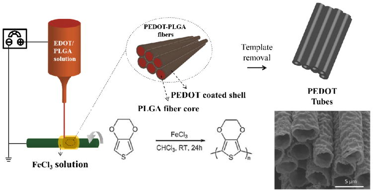
Schematics of the synthesis of PEDOT microtubes using aligned electrospun PEDOT shell/PLGA core microfibers as templates.
2.2. Characterization
A JSM-7400F Scanning Electron Microscope (SEM) operating at 3 kV and an Amray SEM operating at 5 kV were used to obtain secondary electron images of the surface morphology. Samples were sputtered (Technics Hummer VI) with gold/palladium prior to imaging. For the Transmission Electron Microscopy (TEM) measurements, copper grids were put on Scotch® tape for 5 minutes and then taken off. PEDOT-PLGA fibers were stuck onto the copper grids with the glue remnant and examined with a JEOL-2000FX (200 kV LaB6 gun). The DC conductivity of the fibers was determined using a two-point measurement of fiber bundles with a length of 0.48 cm. Conductivity values were normalized by bundle thickness, as determined by SEM images. Raman spectroscopy was obtained with a green laser at 532 nm with a power of 2 mW. TGA was performed using a Perkin-Elmer Thermogravimetric Analyzer (TGA) in a nitrogen environment with heating to 500 °C at a scan rate of 20 °C/min.
2.3. Cell culture and imaging
All animal experiments were conducted in accordance with the guide for the use and care of laboratory animals and approved by the IACUC at the Veterans Affairs Healthcare Center in Ann Arbor. Serum-free culture of dorsal root ganglia (DRG) was performed as previously described. Briefly, the fiber samples were incubated in 0.01% poly-L-lysine (PLL) for 1 hr at room temperature, then dried and rinsed twice in sterile water. DRG were removed whole from E15 rat embryos and placed on the fibers in media. Media consisted of Neurobasal (Invitrogen) supplemented with B27 (Gibco BRL), 30 nM selenium, 10 nM hydrocortisone, 10 nM β-estradiol, 10 mg L-1 apo-transferrin and 2 μM L-glutamine. DRG were fixed six days after plating in 4% paraformaldehyde for 30 minutes. Membranes were permeabilized and non-specific antibody binding was blocked by incubating samples in 1.25% bovine serum albumin, 4% normal goat serum and 0.05% Triton-X-100 for 30 minutes. Rabbit anti-neurofilament (Chemicon, Temecula, CA) was used at 1:1000 to label neurons and mouse S-100 was used at 1:250 to label Schwann cells. Primary antibodies were applied overnight and secondary antibodies were applied for four hours at 1:200. All cell staining procedures were carried out at room temperature. Samples were mounted on slides with Prolong Gold (Invitrogen) containing the nuclear counter-stain DAPI. Images were acquired on Leica stereo and Zeiss confocal microscopes.
3. Results and discussions
3.1. Preparation of PEDOT sheath/PLGA core 1-D microstructure
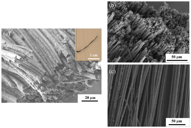
EDOT monomer was mixed into solutions of PLGA [22, 28–29]. Fibers were obtained from the PLGA/EDOT solutions (in a 80:20 (v/v) chloroform: DMF mixed solvent) with different EDOT/PLGA weight ratios, 1:10, 3:10 and 5:10 (w/w), respectively. As the fibers were collected onto the surface of the rotating glass rod, they were oriented circumferentially. As electrospinning was taking place, the aligned fibers were exposed to an aqueous solution of FeCl3 oxidant in order to polymerize the EDOT monomer. After polymerization, residual FeCl3 was removed by soaking the fibers in an excess amount of water for an extended period of time (> 24 hours). The overall alignment of fibers was well preserved after polymerization. The color of the fibers turned to light blue for thinner samples and dark color for thick samples due to the characteristic optical absorption of PEDOT formation (Figure S1). Optical and electron microscopy images of the aligned PEDOT/PLGA fibers bundles are shown in Figure 2(a). PLGA can be removed by soaking the fibers in acetone or chloroform since PEDOT is insoluble in those organic solvents. After the PLGA template was removed, well-aligned conductive PEDOT tubes were formed. An SEM micrograph of the tubes is shown in Figure 2(b) and (c). The PEDOT formed in the aligned microfibers was mechanically stable enough to withstand the template removal without significant collapse or reorganization.
Figure 2.
(a) FE-SEM image and optical image (inset) of aligned PEDOT/PLGA microfibers before template removal. (b), (c) FE-SEM images of aligned PEDOT microtubes after removal of PLGA.
3.2. Microscopy characterization of PEDOT sheath/PLGA core microfibers and PEDOT tubes
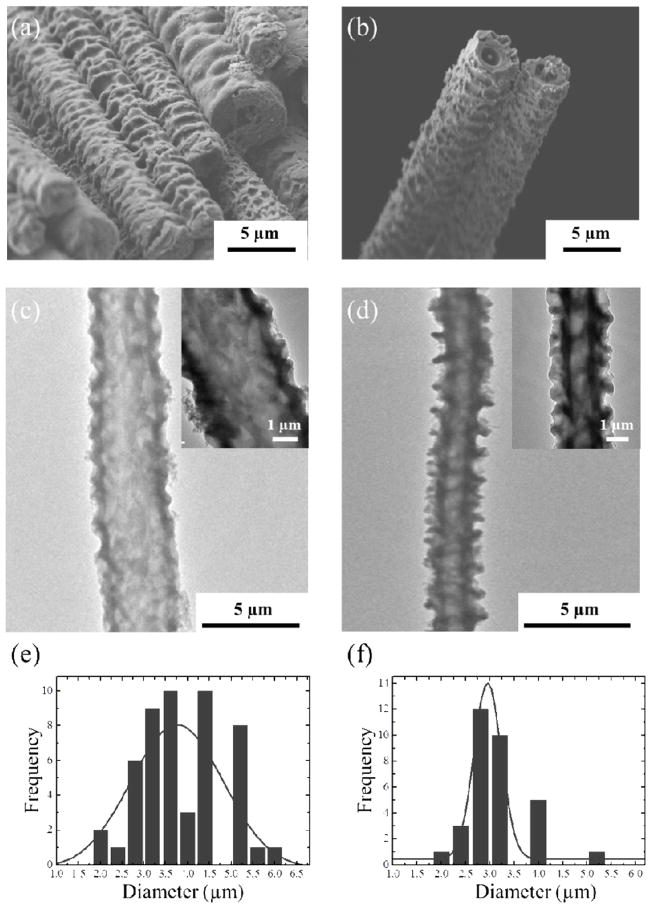
To investigate the formation of aligned PEDOT/PLGA fibers, longitudinal (Figure 3(a), (b)) and cross sectional (Figure 3(c), (d)) SEM images were collected with various EDOT to PLGA weight ratios (1:1, 3:10 or 5:10 (w/w)) under same amount of FeCl3 solution as oxidant (60 wt%). When the EDOT:PLGA ratios of 3:10 (Figure 3(a)) or 5:10 (Figure 3(b)) were employed, fiber bundles having a rough and wrinkled texture were obtained. After washing with chloroform, the fibers exhibited a hollow morphology (Figure 3(c), (d)). The tubes were completely hollow along their entire length and the walls of the interior lumen were uniform and smooth. By unwinding the fibers from the glass rod, it was possible to obtain individual fibers and bundles of fibers of centimeter lengths. In the case of a EDOT:PLGA ratio of 3:10, the diameter of the fibers was 3.7 ± 0.9 μm and it was 2.9 ± 0.6 μm for 5:10 (w/w). Both of these were much smaller than the typical size of the fibers prepared from EDOT:PLGA ratio of 1:10 (w/w) (~ 10 μm, see Figure S2). Interestingly, the thickness of the tube walls (around 500 nm), was not a function of the overall tube diameter. This suggests that PEDOT wall thickness is only dependent on the amount of FeCl3 oxidant solution that diffuses into the tubes over the time frame of the oxidative polymerization.
Figure 3.
Longitudinal FE-SEM and TEM images of PEDOT/PLGA microfibers synthesized from (a), (c) EDOT:PLGA = 3:10 (b), (d) EDOT:PLGA = 5:10. Corresponding sizes of PEDOT/PLGA microfibers are depicted; (e) EDOT:PLGA = 3:10 and (f) EDOT:PLGA = 5:10.
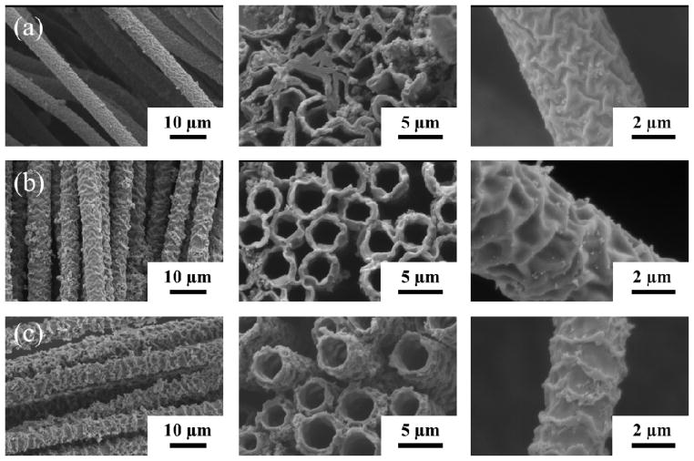
In order to determine the effects of oxidizer concentration, hollow tubes were prepared by varying the amount of FeCl3 oxidant. Figure 4 shows that the surfaces of the fiber become rougher as the oxidizer concentration is increased from 30 wt%, 50 wt%, and 60 wt% respectively. The tubular structure probably originated from the fast polymerization of PEDOT from the outer tube walls, limiting the diffusion of oxidizer into the fibers for further polymerization of the remaining EDOT monomer. Inside the tube, the PLGA and unpolymerized EDOT could be later washed away by an excess amount of acetone. The conductive PEDOT tubes were well aligned, uniform and strong enough to remain open after the washing process. Some evidence of tube collapse was seen if the tube walls were too thin, as in Figure 3c.
Figure 4.
Longitudinal (left, scale bars = 10 μm), cross-sectional (middle, scale bars = 5 μm), and close up (right, scale bars = 2 μm) SEM images of PEDOT fibers electrospun into (a) 30 wt % (b) 50 wt% (c) 60% FeCl3 solutions.
3.3. Conductivity, Raman spectroscopy and thermal analysis of PEDOT sheath/PLGA core microfibers
The DC conductivity of the fibers was measured by using a two point probe (Table 1). The normalized conductivity of fibers obtained by using the ratio between EDOT to PLGA (3:10 and 5:10) ratios were higher than the fibers prepared from EDOT:PLGA (1:10) confirming their dense PEDOT walls. Fibers with lower conductivity were obtained with lower concentrations of oxidizer due to the lower amount of PEDOT formation. This is consistent with the TEM studies that showed that less concentrated oxidizer produced thinner PEDOT walls. (Figure 5)
Table 1.
Resistance (R) of PEDOT fibers obtained by varying the EDOT:PLGA ratios (1:9, 3:7, 1:1, respectively). Conductivity ( ) was obtained from the resistivity ( ). A: cross-sectional area of fibers, l: length (0.48 cm). The diameter of each fiber was obtained from the Figure 3.
| Sample | Average diameter (μm) | Resistance (kΩ) | Conductivity (S/cm) |
|---|---|---|---|
| EDOT:PLGA – 1:10 (60 wt% FeCl3) | 10 | 2.2 | 0.07 |
| EDOT:PLGA – 3:10 (60 wt% FeCl3) | 3.7 | 4 | 0.28 |
| EDOT:PLGA = 5:10 (60 wt% FeCl3) | 2.9 | 7.8 | 0.23 |
| EDOT:PLGA = 3:10 (50 wt% FeCl3) | 3.7 | 13 | 0.09 |
| EDOT:PLGA = 3:10 (30 wt% FeCl3) | 3.7 | 50 | 0.02 |
Figure 5.
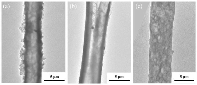
TEM images showing hollow morphology of electrospun PEDOT fibers. TEM images of electrospun EDOT fibers obtained by varying the FeCl3 oxidizer concentration (a) 30 wt % (b) 50 wt% (c) 60 wt%.
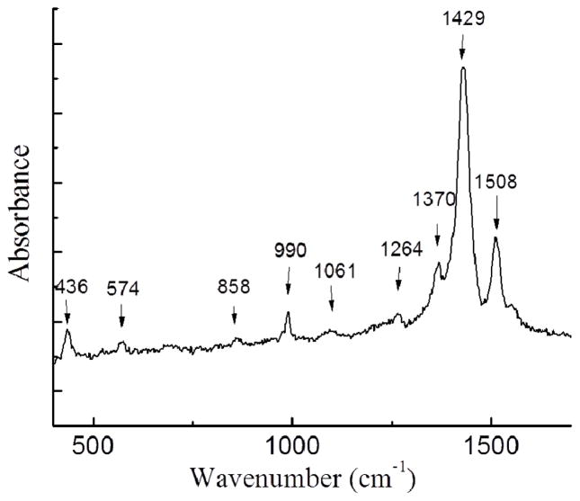
A typical Raman spectrum (λ=532 nm) is shown in Figure 6. The data are all consistent with previous experimental and theoretical studies of PEDOT [30–32]. The peaks at 436 and 574 cm−1 are associated with C-O-C bond deformation. The peak at 858 and 990 cm−1 are assigned to O-C-C deformation and oxyethylene ring deformation respectively. The peaks at 1228 and 1264 cm−1 both originate from the thiophene C-C inter-ring stretching in-plane modes. The peaks at 1061, 1370, 1429 and 1508 cm−1 correspond to C-O stretching, C-C stretching in plane modes, C=C stretching in plane modes (symmetric) and C=C stretching in-plane modes (antisymmetric) respectively as shown in Table 2.
Figure 6.
Raman spectroscopy of PEDOT/PLGA microfibers.
Table 2.
Comparison of the experimental and reference frequencies of Raman spectroscopic results of PEDOT.
| Experimental frequencies (cm−1) | Reference frequencies (cm−1) | |
|---|---|---|
| 1508 | 1509 | C=C strecthing in plane modes (antisym.) |
| 1429 | 1444 | C==C stretching in plane modes (sym.) |
| 1370 | 1366 | C-C stretching in plane modes |
| 1264 | 1267 | C-C inter-ring stretching in plane modes |
| 1228 | 1228 | C-C inter-ring stretching in plane modes |
| 1061 | 1061 | C-O stretching |
| 990 | 988 | oxyethylene ring deformation |
| 858 | 865 | O-C-C deformation |
| 574 | 565 | C-O-C deformation |
| 436 | 440 | C-O-C deformation |
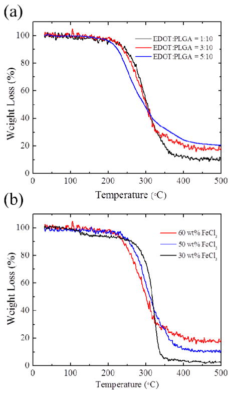
The thermal behavior and the amount of PEDOT polymer in PEDOT/PLGA fibers were investigated by thermogravimetric analysis (TGA) (Figure 7). A significant weight loss in the TGA scans of PLGA was observed in a temperature range from 300 to 400 °C and the decomposition of PLGA is almost completed around 500 °C. The major thermal decomposition of PEDOT occurred from 140–330 °C and there was around 40 wt% carbon left after heating to 500 °C (See Figure S3). Figure 7(a) shows the thermal decomposition of samples with different EDOT:PLGA ratios. There were 11 wt%, 17 wt% and 20 wt% left over for sample A (EDOT:PLGA = 1:10), sample B (EDOT:PLGA = 3:10) and sample C (EDOT:PLGA = 5:10), respectively. This means that samples A, B, C contain approximately 27.5 wt%, 42.5 wt% and 50 wt% of PEDOT in the PEDOT/PLGA fibers. It is noted that sample C has the highest PEDOT/PLGA ratio in the fibers confirmed by its highest PEDOT shell content at PEDOT-PLGA tube (~34 %). Also, the onset decomposition temperature of fibers having more PLGA in them (EDOT:PLGA = 1:10 or 3:10) (~ 260 °C) is slightly higher than that of the other fibers (EDOT:PLGA=5:10) (~ 215 °C) implying that the addition of PEDOT lead to a slight decrease in degradation temperature. Figure 7(b) shows the thermal decomposition of samples prepared with different FeCl3 oxidizer amounts. There were 18 wt%, 11 wt% and 2.5 wt% left over which is attributed to 45 wt%, 27.5 wt% and 6.3 wt% of PEDOT in the PEDOT/PLGA fibers respectively. It tells us that the lower amount of FeCl3 produced lower amount of PEDOT shell in the PEDOT/PLGA fibers as corroborated with the TEM morphology (Figure 5) and conductivity results. Thus, the fibers that have more PLGA in them (those with 30 wt% FeCl3) show slightly higher decomposition temperatures.
Figure 7.
TGA of PEDOT/PLGA fibers obtained by (a) varying the ratio between EDOT to PLGA (A) 1:10 (B) 3:10 (C) 5:10 (b) varying the concentration of FeCl3 oxidizer solutions (A) 60 wt % (B) 50 wt % (C) 30 wt %.
3.4. Cell growth
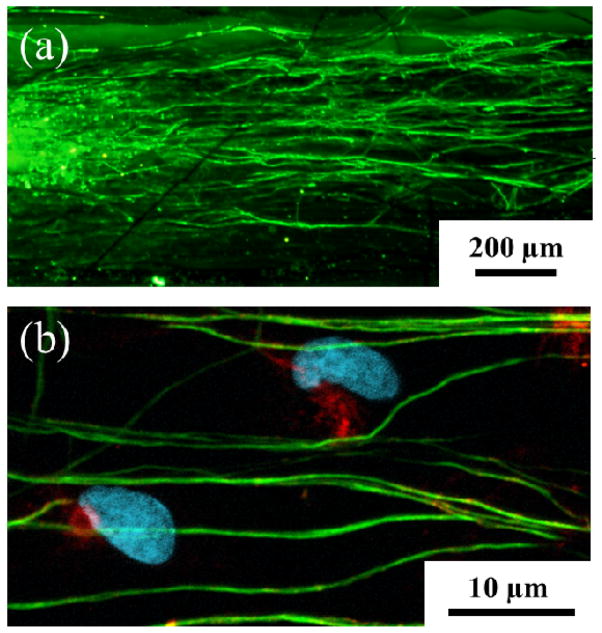
To investigate the ability of the PEDOT nano- and microfibers to direct neural regeneration, dorsal root ganglia (DRG) were cultured on bundles of PEDOT microfibers in defined media. Immunochemistry revealed that the DRG sensory neurons adhered to the PEDOT fiber bundles and sent out neurites that precisely followed the direction of fiber alignment as shown in Figure 8(a). Additionally, Schwann cells migrated out of the body of the DRGs along the PEDOT fibers and exhibited their classic spindle-shaped morphology as shown in Figure 8(b). The DRGs were cultured for a period of six days and the extent of neurite outgrowth indicated good biocompatibility with the PEDOT fibers.
Figure 8.
(a) Confocal image of DRG neurites cultured on the aligned electrospun PEDOT microfibers. Beta-tubulin (green), a structural component of neurons, indicates that the DRG neurites followed the direction of fiber alignment (horizontal). (b) Schwann cells are identified by co-localization of s100 (red) and DAPI (blue). Scale bars: 200 μm (a) and 10 μm (b).
4. Conclusions
We have successfully synthesized aligned poly(3,4-ethylene dioxythiophene) (PEDOT)/poly(lactide-co-glycolide) (PLGA) nano-/microfibers and PEDOT nano-/microtubes through electrospinning of 3,4-ethylene dioxythiophene (EDOT) monomer/PLGA polymer blends and chemical polymerization of PEDOT. We have shown that PEDOT wall thickness is highly dependent on the amount of FeCl3 oxidizer instead of EDOT: PLGA ratio. The results indicate that PEDOT preferentially polymerized at the outer tube walls tuned by the FeCl3 oxidizer concentration, which controls the degree of FeCl3 solution diffusion over the time frame of the oxidative polymerization. Higher oxidizer produced rougher fiber/tube surfaces while the lowest oxidizer concentrations resulted in significant collapse of the tubes due to the insufficient PEDOT polymerization. The conductivities of the fibers were influenced by the PEDOT wall thickness instead of fiber diameters, which was confirmed by thermal analysis. Raman spectroscopic results confirmed the PEDOT formation in the microfibers. The key advantage of this approach is its versatility at directing neural regeneration or use as a potent drug delivery system.
Supplementary Material
Footnotes
Publisher's Disclaimer: This is a PDF file of an unedited manuscript that has been accepted for publication. As a service to our customers we are providing this early version of the manuscript. The manuscript will undergo copyediting, typesetting, and review of the resulting proof before it is published in its final citable form. Please note that during the production process errors may be discovered which could affect the content, and all legal disclaimers that apply to the journal pertain.
References
- 1.Kirchmeyer S, Reuter KJ. Mat Chem. 2005;15:2077–2088. [Google Scholar]
- 2.Groenendaal L, Jonas F, Freitag D, Pielartzik H, Reynolds JR. Adv Mater. 2000;7:481–494. [Google Scholar]
- 3.Yang J, Martin DC. Sensors and Actuators A: Physical. 2004a;113:204–211. [Google Scholar]
- 4.Lock JP, Im SG, Gleason KK. Macromolecules. 2006;39:5326–5329. [Google Scholar]
- 5.Aleshin AN. Adv Mater. 2006;18:17–27. [Google Scholar]
- 6.Law M, Goldberger J, Yang P. Annu Rev Mater Res. 2004;34:83–122. [Google Scholar]
- 7.Cho S, Lee SB. Acc Chem Res. 2008;41:699–707. doi: 10.1021/ar7002094. [DOI] [PubMed] [Google Scholar]
- 8.Li N, Martin CR, Scrosati B. Electrochem Solid State Lett. 2000;3:316–318. [Google Scholar]
- 9.Cassagneau T, Caruso F. Adv Mater. 2002;14:1837–1841. [Google Scholar]
- 10.Xiao R, Cho S, Liu R, Lee SB. J Am Chem Soc. 2007;129:4483–4489. doi: 10.1021/ja068924v. [DOI] [PubMed] [Google Scholar]
- 11.Han MG, Foulger SH. Small. 2006;2:1164–1169. doi: 10.1002/smll.200600135. [DOI] [PubMed] [Google Scholar]
- 12.Zhang X, Lee JS, Lee GS, Cha DK, Kim MJ, Yang DJ, Manohar SK. Macromolecules. 2006;39:470–472. [Google Scholar]
- 13.Zhou Y, Freitag M, Hone J, Staii C, Johnson AT, Pinto NJ, MacDiarmid AG. Appl Phys Lett. 2003;83:3800–3802. [Google Scholar]
- 14.Huang Z, Zhang Y, Kotaki M, Ramakrishna S. Composites Science and Technology. 2003;63:2223–2253. [Google Scholar]
- 15.Corey JM, Lin DY, Mycek KB, Chen Q, Samuel S, Feldman EL, Martin DC. J Biomed Mater Res Part A. 2007;83A:636–645. doi: 10.1002/jbm.a.31285. [DOI] [PubMed] [Google Scholar]
- 16.Cui X, Martin DC. Sensors and Actuators B: Chemical. 2003;89:92–102. [Google Scholar]
- 17.Yang J, Kim DH, Hendricks JL, Leach M, Northey R, Martin DC. Acta Biomat. 2004;1:125–136. doi: 10.1016/j.actbio.2004.09.006. [DOI] [PubMed] [Google Scholar]
- 18.Yang J, Martin DC. Sensors and Actuators B: Chemical. 2004b;101:1–2. [Google Scholar]
- 19.Xiao Y, Martin DC, Cui X, Shenai M. Appl Biochem Biotech. 2006;128:117–129. doi: 10.1385/abab:128:2:117. [DOI] [PubMed] [Google Scholar]
- 20.Yang J, Lipkin K, Martin DC. J Biomater Sci Polym Ed. 2007;18:1075–1089. doi: 10.1163/156856207781494359. [DOI] [PubMed] [Google Scholar]
- 21.Martin DC, Wu J, Shaw CM, King Z, Spannigga SA, Richardson-Bruns S, Hendrick J, Yang J. Polym Rev. 2010;50:340–384. [Google Scholar]
- 22.Abidian MR, Kim DH, Martin DC. Adv Mater. 2006;18:405–409. doi: 10.1002/adma.200501726. [DOI] [PMC free article] [PubMed] [Google Scholar]
- 23.Abidian MR, Martin DC. Biomaterials. 2008;29:1273–1283. doi: 10.1016/j.biomaterials.2007.11.022. [DOI] [PMC free article] [PubMed] [Google Scholar]
- 24.Abidian MR, Martin DC. Adv Funct Mater. 2009;19:573–585. [Google Scholar]
- 25.Bellamkonda RV, Pai B, Renaud P. MRS Bulletin. 2012;37:557–561. [Google Scholar]
- 26.Corey JM, Gertz CC, Wang BS, Birrell LK, Johnson SL, Martin DC, Feldman EL. Acta Biomat. 2008;4:863–875. doi: 10.1016/j.actbio.2008.02.020. [DOI] [PMC free article] [PubMed] [Google Scholar]
- 27.Green RA, Lovell NH, Wallace GG, Poole-Warren LA. Biomaterials. 2008;29(24–25):3393–3399. doi: 10.1016/j.biomaterials.2008.04.047. [DOI] [PubMed] [Google Scholar]
- 28.Li W, Laurencin CT, Caterson EJ, Tuan RS, Ko FK. J Biomed Mater Res. 2002;60:613–621. doi: 10.1002/jbm.10167. [DOI] [PubMed] [Google Scholar]
- 29.Yoshimoto H, Shin YM, Terai H, Vacanti JP. Biomaterials. 2003;24:2077–2082. doi: 10.1016/s0142-9612(02)00635-x. [DOI] [PubMed] [Google Scholar]
- 30.Nguyen TP, Rendu PL, Long PD, De Vos SA. Surf Coat Tech. 2004;180–181:646–649. [Google Scholar]
- 31.Xu Q, Czernuszka JT. J Controlled Release. 2008;127:146–153. doi: 10.1016/j.jconrel.2008.01.017. [DOI] [PubMed] [Google Scholar]
- 32.Tran-Van F, Garreau S, Louarn G, Froyer G, Chevrot C. J Mater Chem. 2001;11:1378–1382. [Google Scholar]
Associated Data
This section collects any data citations, data availability statements, or supplementary materials included in this article.


