Abstract
We demonstrate a valve-less microfluidic peristaltic pumping method which enables the delivery of continuous nanoliter-scale flow with high precision. The fluid is driven by squeezing the microchannels embedded in a poly(dimethylsiloxane) device with rolling cams or bearings. We achieve continuous and uniform flow with velocity range from 1 to 500 nl/s, with outflow volume error within 3 nl. The devices show enhanced backpressure resistance up to 340 kPa. This method also shows great flexibility. By altering the channels' layout, emulsions and plugs can be generated easily. These low-cost and easy-to-fabricate micro-pumps offer novel approaches for liquid actuation in various microfluidic applications.
INTRODUCTION
Microfluidic flow control is becoming a critical technology and getting widely used because of the need for precise manipulation of low-quantity liquid sample in both lab-on-a-chip1 and point-of-care2 applications.3 Although most microfluidic chips are designed in compact formats, many of them still rely on bulky equipment that externally connected to the chips with micro-bore tubing to provide reagents or air-pressure.4–9 These external instruments enable precise control of fluids but also increase the complexity which limits the usage of microfluidic devices in less equipped environments. To simplify the liquid driving mechanism and fully utilize the advantage of microfluidics, a desired micro-pumping system should be small in size, precise in operation, ready to be integrated with compact chips, and scalable to drive multiple flow channels in parallel.
Many conventional pumping techniques can drive fluids in micro-channels.10,11 Among these techniques, some off-chip pumps have been widely used because of their well-characterized performance and straightforward operation.12 Sucking by vacuum13 or pushing by compressed air6 are the simplest means to drive liquids on-chip. However, precisely metering is commonly challenging. Currently, syringe pumps9 and external peristaltic pumps14 are the dominant working horses, but they typically exhibit a few limitations including relatively high costs, bulky sizes, and large dead volumes at the world-to-chip interface.
A number of on-chip pumping mechanisms have been introduced to cope with the existing challenges. The peristaltic pumps that are based on poly(dimethylsiloxane) (PDMS) valves are extremely precise but require multi-layer soft lithography and external solenoid valves to operate.15 The outflow is pulsatile, especially when the peristaltic pumps work at the low velocity. Alternations such as magnetic actuation,16 thermal expansion,17 and direct pressing using screw18 or Braille displays19 have also been demonstrated. Other chip-based methods have employed capillary force20 or centrifugal force,21 but they have had difficulty providing long-term stable continuous flow with fine control.
Some previous reports have demonstrated a pumping mechanism that uses rolling balls to squeeze circular channels embedded in PDMS-chips.22,23 It makes continuous outflow and is ready for integration into microfluidic devices with reduced dead volume. However, the magnetic-based driving mechanism, rather than direct driving, introduces extra complexity and reduces stability and robustness of the system. The channels in these devices were relatively wide (∼2 mm) to fit the balls and to get fully compressed. This dimension limits the popularization of rolling-ball pumps in the applications that require precise control of liquid flow down to nL/s or when multiple channels need to be controlled.
Here, we demonstrate a practical approach of chip-based, valve-less planar peristaltic micro-pumps. The primal design is a “linear-shape” micro-pump with continuous outflow but with intrinsic back-flow and strokes. The improved design is a “round-shape” micro-pump, in which the circular micro-channels embedded in PDMS are squeezed by bearings, enabling continuous, steady, and precise fluidic perfusion with optimized channel layout. Compared with conventional valve-based on-chip pumps, this approach reduces the complexity of chip designs and fabrication with single-layer lithography and is able to deliver smooth outflow. We have also performed simultaneous control on multiple flows by squeezing parallel channels. Additionally, multiple flows with different relative velocity have been achieved by controlling channel-width. We have generated multiphase emulsion and plug flows with this valve-less micro-pump. This chip-top operation provides a simple and precise way to control microfluidic flow, with great flexibility to be seamlessly integrated with other applications.
EXPERIMENTAL
The linear-shape micro-pump
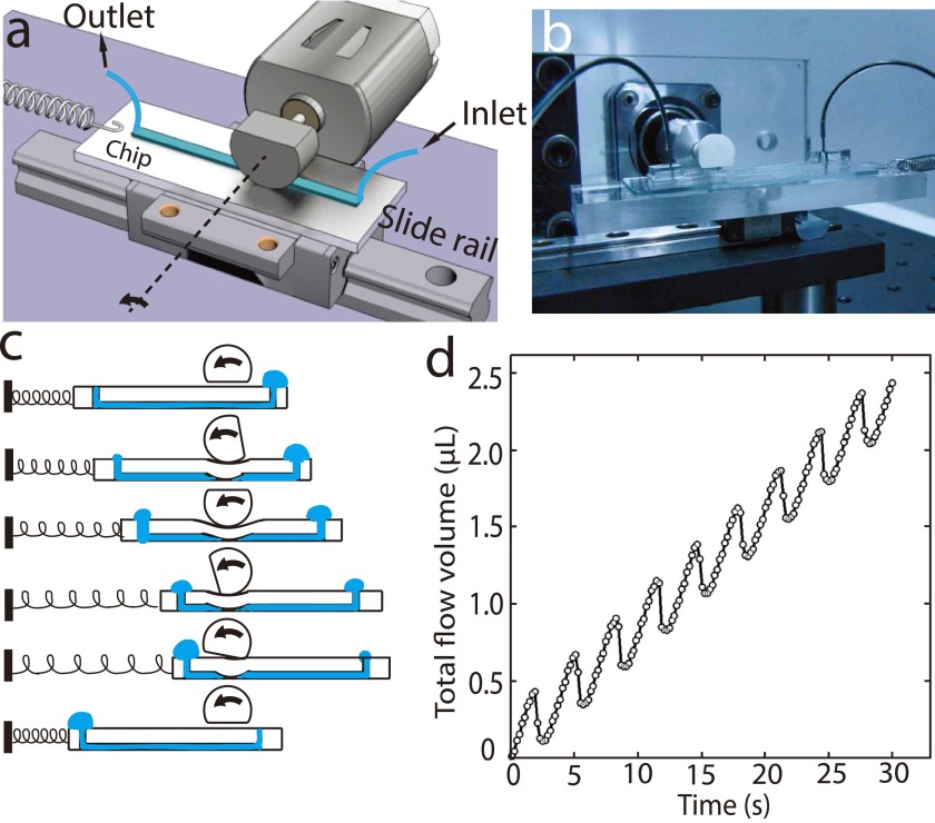
A cam was connected to the stepper motor with a shaft joint (Figs. 1(a) and 1(b)). The stepper motor was driven by a microstep motor driver (CW250AC, Chuangwei-motor Ltd, China) with the microstep set at 1/256. A DC power supply (6632B, Agilent, Palo Alto, CA, USA) and a function generator (AFG3022C, Tektronix, Beaverton, Oregon, USA) were used to support the driver. The cam was made of nylon through 3D printing, with a radius of 6 mm. The PDMS chip, with a linear micro-channel embedded, was set on a linear slide rail. The chip was fabricated by plasma bonding a PDMS sheet (Height = 1.5 mm) replicated from a silicon mold, with a piece of glass permanently. The mold was made of AZ50XT (AZ Electronic Materials, Branchburg, NJ, USA) photoresist with thickness ∼50 μm, and was patterned with photolithography to define a channel (width = 200 μm and length = 4 cm). We rounded the channel-pattern on mold by heating the wafer at 150 °C for 2 h.24 Mechanism of fluidic delivering is shown in Fig. 1(c), in which cam and spring enables the auto ‘reset’ of the pump thus providing quasi-continuous outflow. We placed the cam on top of the linear channel and adjusted the position between cam and chip to ensure that the deformed PDMS slab blocked the channel. As the cam rotates, it pulls the chip along the slide rail and stretches the spring. At the end of each cycle, the flat part of the cam loses contact with the chip and the released chip is pulled back by the spring.
FIG. 1.
The round-shape micro-pump
Round-shape micro-pump (Fig. 2(a)) has a similar structure with “linear-shape” one except with curve channels. Oxygen-plasma treatment before bonding is critical for tight sealing. We installed two bearings (SKF, Sweden; d = 2.5 mm, D = 6 mm) on two ends of a “T”-shape arm (L = 30 mm) and then mounted it to a stepper motor with a spring shaft joint. The diameter of the circular pattern was 33 mm. The motor axis was aligned at the centroid of the circular pattern. While the T-arm rotating, at least one bearing is kept on the channel, squeezing the channel and driving the liquid. The bearing is 2.6 mm wide while a typical channel is only 0.1–0.25 mm, allowing integration of multiple channels in parallel to construct a multiplex peristaltic pump.The characterization of micro-pumps
FIG. 2.
The structure and characterization of round-shape micro-pumps. (a) Two bearings mounted on T-shape arm squeezing on a PDMS made chip with a circular track. (b) The photograph of a device. (c)–(e) The outflow stability is improved with channels using curved inlet/outlet joints and the buffer chamber. (d) A modified channel pattern with rounded in/outlet junctions shows improved outflow consistency. (e) The optimized channel pattern with additional buffer-chamber shows ideal uniform outflow. (f) The outflow volume with time at four rotating speeds. (g) Flow rate shows perfect linearity between rotation speed and flow rate.
The outflow was pumped into Tygon microbore tubing (Saint-Gobain, Aurora, OH, USA, I.D. = 0.76 mm) or glass capillary (I.D. = 0.5 mm) and placed under a digital microscope (GE-5, Aigo, China). Red dye aqueous solution is used as a working fluid for imaging. The images were taken at rate of 1 fps and processed with Matlab (MathWorks, USA). We measured the pumping velocity by analyzing the increase of the length perfused with liquid inside the tubing under certain period of time.
RESULTS AND DISCUSSION
In a cam-driven linear micro-pump, the outflow was pulsatile. Fig. 1(d) shows a typical flow pattern with cam rotating at 18.5 rpm. When the cam squeezed the channel on-chip, the liquid was pumped from inlet (right) to outlet (left) [Fig. 1(c)] and the chip itself slid from left to right. At each cycle, when the cam's flat edge turned to downside, the spring would pull the chip back to the original position (left side in Fig. 1(c)). As the spring released, we observed an obvious backflow [Fig. 1(d), (Multimedia view)] due to the PDMS deformation recovery from the squeeze.25 Since in each cycle the volume of the back-flowed liquid is less than the liquid that been moved forwardly, the device would still pump the liquid through the micro-channel from one port to the other.
The cam-driven linear micro-pump is easy to fabricate and operate. The channel is the simplest layout, which can be further scaled up to multichannel if needed. By altering the channel width, the flow rate can range from a few nl/s to a few μl/s to meet the demands of many applications. However, its characteristic backflow pattern makes the pumping inefficient. At lower time-resolution, the flow can be considered quasi-continuous, while for many microfluidic applications that the typical flow rate is only a few nL/s, the backflow at every pumping stroke is unfavorable. Various modifications could be applied to this design to reduce the pulsed backflow and to improve the pumping efficiency, for example, adding the check valves in the pipeline.
A simpler and more effective solution would be driving the liquid by multiple squeezing sites along the microfluidic channel, and ensuring that the channel is always blocked by at least one squeezing site to prevent the backflow. To have multiple squeezing sites along the micro-channel, we applied a new design with round-shape layout of the fluidic channel (Fig. 2(a)). This design greatly improved the continuity and stability of the flow, and more importantly, the motors used in these designs can potentially be miniaturized to fit in portable devices. The pump had two bearings, fixed on a “T”-shape arm, to squeeze the channel. When the motor rotates, the liquid inside the channel will be driven through peristaltic squeezes (Fig. 2(b)). Notably, during the operation, at least one bearing will always sit on the channel. The adoption of direct-pressing rather than the previously reported magnetic-force driven rolling ball approach ensures more precise and robust driving, enabling small channel width to be employed in the devices. Thus, it becomes possible to fully utilize the flexibility of channel patterning.
We found that the liquid flow still showed small fluctuations when the bearings approaching the channel outlet, in which position the bearings will squeeze the sharp turns between outlet and the circular channel, bringing an abnormally instant increase in velocity followed by a short-term backflow (Fig. 2(c)). An improved channel pattern, by smoothing the joint part of in/outlet and the circular channels with curved connections, could partially solve this problem (Fig. 2(d)). In this design, the bearings would not generate unacceptable velocity increase but the backflow still existed when the bearings moved away from the channels.
To simply eliminate the backflow, we introduced a “buffer chamber” (Fig. 2(e)), which was placed outside the moving track of bearings, upstream of the outlet port. Whenever one bearing moves off the channel, the fluid will retract, but the buffer volume in the chamber can compensate this effect and effectively reduce the backflow. This simple design shows great improvement of pumping performance by reducing the pulsation of liquid flow. The buffer chambers can also be placed cascaded in series to enhance the effect. Each buffer chamber has a typical volume of 100 nl, which is also the dead volume of the device. To avoid fluid loss, the fluid left in the buffer chambers can be pushed out by the replacement of an immiscible liquid (e.g., mineral oil for aqueous solution).
The velocity of pump can be well controlled by adjusting the rotation speed of the motor. To demonstrate the consistency of the micro-pump at different rotating speed, we measured the flow velocity when the motor rotated at 0.6, 1.2, 2.4, and 4.8 rpm (Fig. 2(f)). The fitted slopes of 2.66, 5.43, 10.98, and 21.8 nl/s indicated the system's robust response on varied velocities. It also validates the reproducibility of the device on separate experiments (Fig. 2(g)).
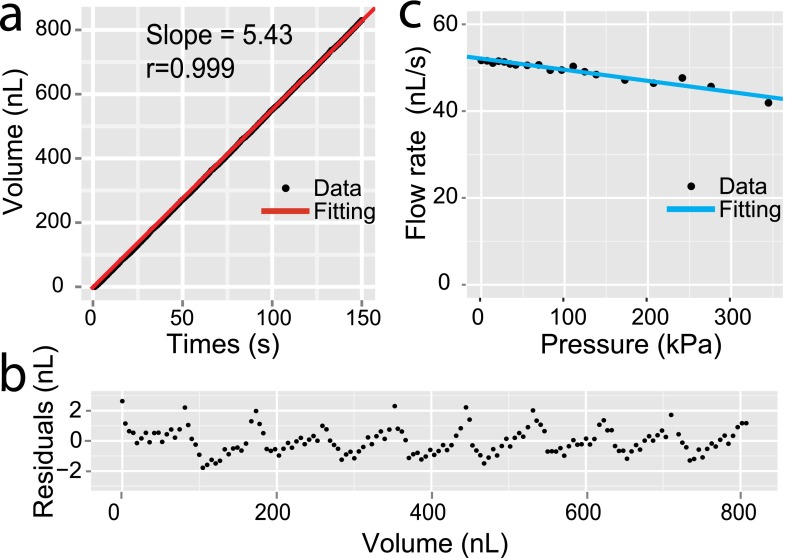
For many small-scale biochemical applications, precise delivery of liquid at microliter and sub-microliter levels is essential to the miniaturized devices or systems. Peristaltic pumps, with intrinsic pulsation flow patterns, have limited accuracy when the delivery scale reaches sub-microliters. We set the rotational speed at 1.2 rpm and measured the outflow volume according to the pumping time (Fig. 3(a)). We plot the residuals according to outflow volume in Fig. 3(b). The data show that the delivery error is not larger than ±3 nl across a wide range of pumping volume. We thus access that, if the relative metering error is limited to be less than 10%, a practical lower limit of the working volume of this pump will be around 30 nl.
FIG. 3.
The precision and stability of a round-shape micro-pump. (a) The outflow volume as a function of time. The flow rate is 5.43 nl/s through linear fitting. (b) The residuals of the linear model between fitted and measured outflow at different outflow volume. The residuals show consistent distribution at wide outflow range. (c) Pump flow rate as a function of backpressure. The data are obtained with rotation speed of 7.5 rpm and channel width of 0.2 mm.
We then measured the flow rate of this pump device under different backpressure (BP), ranging from 0 to 340 kPa (Fig. 3(c)). The device shows good resistance to high BP. At 300 kPa BP, the flow rate drops by 14.7%. Compared to most commercial peristaltic pumps that typically claim to resist to 100 kPa BP, our device is a significant improvement. The enhancement is probability caused by the small scale of the channel in microfluidic devices.
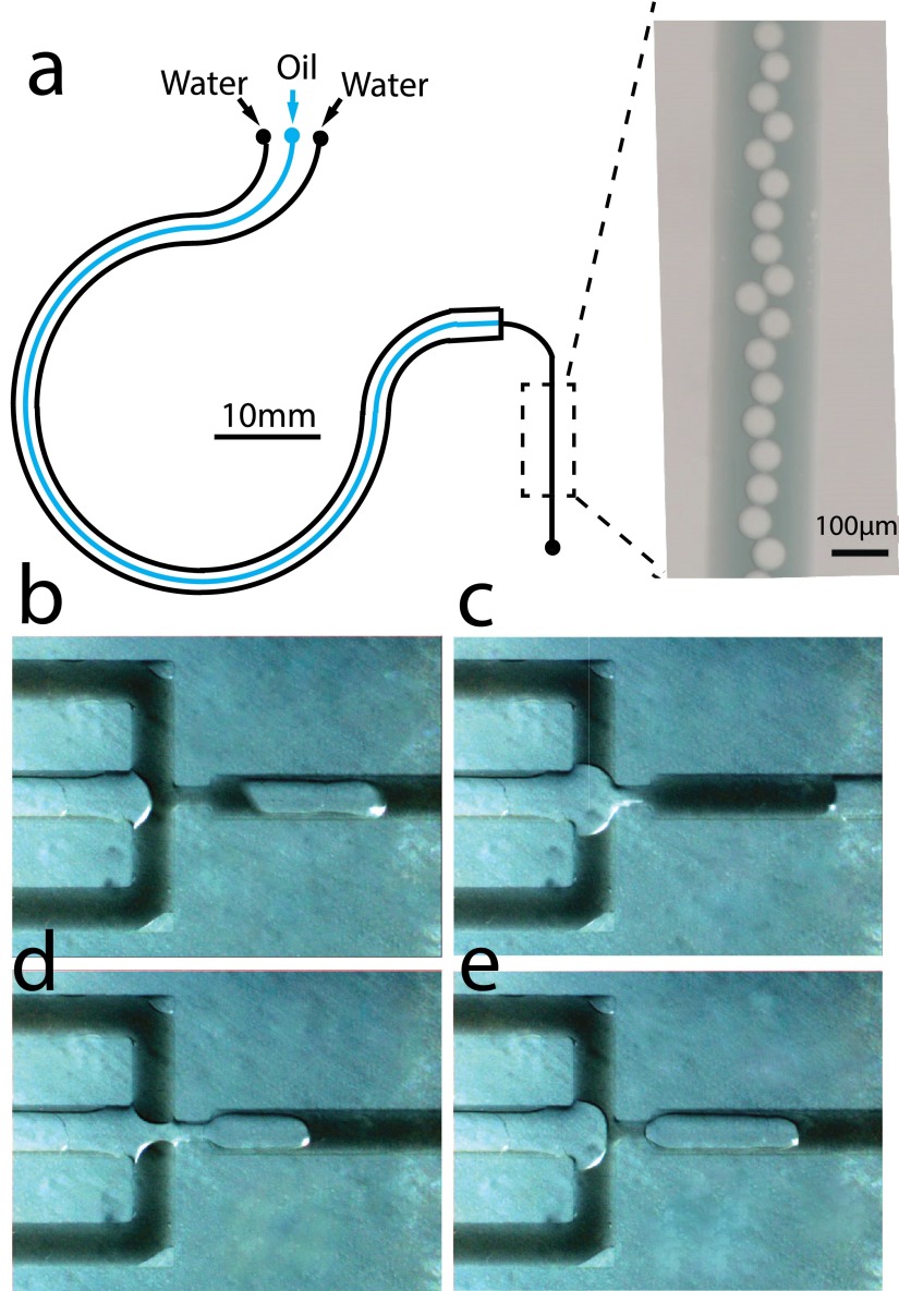
We next demonstrated a multichannel micro-pump to exploit the flexibility of channel patterning in the microfluidic devices made of PDMS. We placed three adjacent microfluidic channels in parallel, and curved them to suit the track of bearings (Fig. 4(a)). We introduced silicon oil (Trimethylsiloxy terminated PDMS, M.M. 770, Alfa Aesar Co., Inc.) and two streams of water (aqueous dye solution) to the inputs and combined all channels into a T-junction. Oil droplets or plugs were generated with bearings squeezing over the channels [Figs. 4(b)–4(e), (Multimedia view)]. Different ratio between fluids can be performed with predesigned set of channels widths. As for multiphase flow, the squeezing speed influences the formation of either droplets or plugs. Under the high-speed conditions, forming smaller droplets is preferred; while at lower speed, larger plugs tend to form at the two-phase interface. The formation of two-phase patterns is robust, owing to the stableness of pumped flow.
FIG. 4.
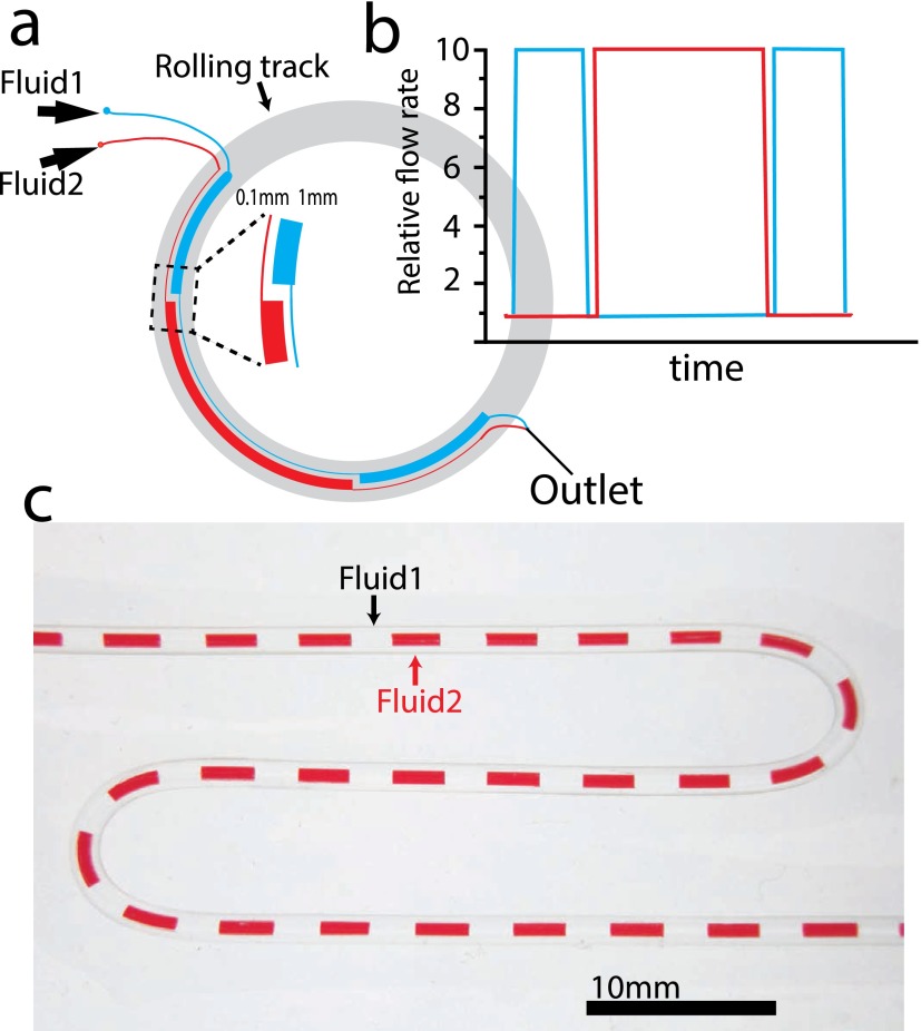
We also extended the flexibility of this pumping mechanism by designing the microfluidic devices with altering-width channels. With this approach, any multi-input flow pattern could be generated simply by pre-designed layout of channels (Fig. 5(a)). Different from the surface tension controlled two-phase flow,26 in this design, each channel is continuous but the width is not constant. We expected that when the bearings squeezed over the channels, the flow rate of each channel was proportional to its width at the squeezing point (Fig. 5(b)). The combined flow was fed into a micro-tubing (Fig. 5(c)), to show the modulation pattern between two liquids. This modulated flow can be widely used in reactant mixing (single-phase) or plug generation (multi-phase) at the sub-microliter scales. We have tested the stability of the modulation with different segmentation volumes, and found that the system achieved stable reproducibly when the segment volume was greater than 100 nl.
FIG. 5.
Multi-phase flow through squeezing pre-patterned channels. (a) The pattern of a two-channel design. (b) The expected relative outflow of two fluids. (c) The combined two-phase outflow that delivered into a micro-tubing.
The pattern of the channels can be flexibly designed as long as their widths can be completely covered by the bearings. When a bearing squeezes along a channel and pushes the downstream liquid, the upstream liquid will passively fill in the channel. We discovered, however, that the peristaltic pumping driven by rolling bearings did not always work well when the channels were too narrow. Narrow channels greatly increase the flow resistance and cause difficulty for liquid to flow fast enough to catch the bearing's moving speed. Since PDMS was gas permeable, air-bubbles would be generated inside the channels when we increased the moving speed of bearings. We observed that more viscous the fluid is, easier the air bubbles would appear. When the channel was 100 μm wide and 30 μm high, and water as working fluid, the air bubbles would not arise inside the channel until the rolling speed reached 16 mm/s. In practical, channel width from 200 μm to 2 mm was preferred, and water could be easily pumped at the flow rate from 1 to 500 nl/s. Compared to commercial peristaltic pumps, which ranges from 1 μl/min to 24 ml/min, our devices have much higher precision of flow rate control, indicating that it is more suitable for miniaturized devices. The backpressure resistance is also increased correspondingly. Compared to some laboratory build peristaltic pumps,8 our device shows better uniformity and reduced pulsating flow.
CONCLUSIONS
We have developed a practical pumping system for low-cost, easy-to-fabricate, and precise control of fluid, with greatly improved flow uniformity and stability for microfluidic devices. The flow velocity can be precisely controlled at the range of 1 ∼ 500 nl/s, which is compatible with most microfluidic biochemical analyses. We have also demonstrated that the error of outflow volume is less than 3 nl. These devices show great backpressure resistance up to more than 340 kPa. The micro-pump can fully utilize the flexibility of channel patterning of chip with multi-channel integration and multi-flow synchronization, effectively reducing the complexity of liquid control in multi-input microfluidic devices. This peristaltic pumping mechanism holds great potential to be integrated into various existing microfluidic applications, including both single-phase and multi-phase complex flows. This method provides a novel approach for driving liquid in miniature analytical systems, and to meet the increasing demands of inexpensive and robust point-of-care diagnostic devices.
ACKNOWLEDGMENTS
The authors thank Dr. Aaron Streets and Tao Chen for the help and discussions. This work was supported by National Natural Science Foundation of China (Grant Nos. 21222501, 91313302, and 21327808 to Y.H.).
References
- 1.Stone H. A., Stroock A. D., and Ajdari A., Annu. Rev. Fluid Mech. 36, 381–411 (2004). 10.1146/annurev.fluid.36.050802.122124 [DOI] [Google Scholar]
- 2.Chin C. D., Linder V., and Sia S. K., Lab Chip 12, 2118–2134 (2012). 10.1039/c2lc21204h [DOI] [PubMed] [Google Scholar]
- 3.Whitesides G. M., Nature 442, 368–373 (2006). 10.1038/nature05058 [DOI] [PubMed] [Google Scholar]
- 4.Thorsen T., Maerkl S. J., and Quake S. R., Science 298, 580–584 (2002). 10.1126/science.1076996 [DOI] [PubMed] [Google Scholar]
- 5.Liu J., Hansen C., and Quake S. R., Anal. Chem. 75, 4718–4723 (2003). 10.1021/ac0346407 [DOI] [PubMed] [Google Scholar]
- 6.Bong K. W., Chapin S. C., Pregibon D. C., Baah D., Floyd-Smith T. M., and Doyle P. S., Lab Chip 11, 743–747 (2011). 10.1039/c0lc00303d [DOI] [PubMed] [Google Scholar]
- 7.Streets A. M. and Huang Y. Y., Biomicrofluidics 7, 011302 (2013). 10.1063/1.4789751 [DOI] [PMC free article] [PubMed] [Google Scholar]
- 8.Skafte-Pedersen P., Sabourin D., Dufva M., and Snakenborg D., Lab Chip 9, 3003–3006 (2009). 10.1039/b906156h [DOI] [PubMed] [Google Scholar]
- 9.Song H., Tice J. D., and Ismagilov R. F., Angew. Chem. Int. Ed. 42, 768–772 (2003). 10.1002/anie.200390203 [DOI] [PubMed] [Google Scholar]
- 10.Iverson B. D. and Garimella S. V., Microfluid. Nanofluid. 5, 145–174 (2008). 10.1007/s10404-008-0266-8 [DOI] [Google Scholar]
- 11.Laser D. J. and Santiago J. G., J. Micromech. Microeng. 14(6), R35–R64 (2004). 10.1088/0960-1317/14/6/R01 [DOI] [Google Scholar]
- 12.Pennathur S., Lab Chip 8(3), 383–387 (2008). 10.1039/b801448p [DOI] [PubMed] [Google Scholar]
- 13.Stiles T., Fallon R., Vestad T., Oakey J., Marr D. W. M., Squier J., and Jimenez R., Microfluid. Nanofluid. 1, 280–283 (2005). 10.1007/s10404-005-0033-z [DOI] [Google Scholar]
- 14.Zhou Y., Pang Y. H., and Huang Y. Y., Anal. Chem. 84, 2576–2584 (2012). 10.1021/ac203469v [DOI] [PubMed] [Google Scholar]
- 15.Unger M. A., Chou H. P., Thorsen T., Scherer A., and Quake S. R., Science 288, 113–116 (2000). 10.1126/science.288.5463.113 [DOI] [PubMed] [Google Scholar]
- 16.Shen M., Dovat L., and Gijs M. A. M., Sens. Actuators, B 154, 52–58 (2011). 10.1016/j.snb.2009.10.033 [DOI] [Google Scholar]
- 17.Chia B. T., Liao H. H., and Yang Y. J., Sens. Actuators, A 165, 86–93 (2011). 10.1016/j.sna.2010.02.018 [DOI] [Google Scholar]
- 18.Weibel D. B., Kruithof M., Potenta S., Sia S. K., Lee A., and Whitesides G. M., Anal. Chem. 77, 4726–4733 (2005). 10.1021/ac048303p [DOI] [PubMed] [Google Scholar]
- 19.Gu W., Zhu X. Y., Futai N., Cho B. S., and Takayama S., Proc. Natl. Acad. Sci. U.S.A. 101, 15861–15866 (2004). 10.1073/pnas.0404353101 [DOI] [PMC free article] [PubMed] [Google Scholar]
- 20.Juncker D., Schmid H., Drechsler U., Wolf H., Wolf M., Michel B., de Rooij N., and Delamarche E., Anal. Chem. 74, 6139–6144 (2002). 10.1021/ac0261449 [DOI] [PubMed] [Google Scholar]
- 21.Lai S., Wang S., Luo J., Lee L. J., Yang S. T., and Madou M. J., Anal. Chem. 76, 1832–1837 (2004). 10.1021/ac0348322 [DOI] [PubMed] [Google Scholar]
- 22.Yobas L., Tang K. C., Yong S. E., and Ong E. K. Z., Lab Chip 8, 660–662 (2008). 10.1039/b720024b [DOI] [PubMed] [Google Scholar]
- 23.Yobas L., Cheow L. F., Tang K. C., Yong S. E., Ong E. K. Z., Wong L., Teo W. C. Y., Ji H. M., Rafeah S., and Yu C., Biomed. Microdev. 11, 1279–1288 (2009). 10.1007/s10544-009-9347-z [DOI] [PubMed] [Google Scholar]
- 24.Futai N., Gu W., and Takayama S., Adv. Mater. 16, 1320 (2004). 10.1002/adma.200400595 [DOI] [Google Scholar]
- 25.Hardy B. S., Uechi K., Zhen J., and Kavehpour H. P., Lab Chip 9, 935–938 (2009). 10.1039/b813061b [DOI] [PubMed] [Google Scholar]
- 26.Zheng B., Roach L. S., and Ismagilov R. F., J. Am. Chem. Soc. 125, 11170–11171 (2003). 10.1021/ja037166v [DOI] [PubMed] [Google Scholar]


