Abstract
Millions of patients are either slowly losing their vision or are already blind due to retinal degenerative diseases such as retinitis pigmentosa (RP) and age-related macular degeneration (AMD) or because of accidents or injuries. Employment of artificial means to treat extreme vision impairment has come closer to reality during the past few decades. Currently, many research groups work towards effective solutions to restore a rudimentary sense of vision to the blind. Aside from the efforts being put on replacing damaged parts of the retina by engineered living tissues or microfabricated photoreceptor arrays, implantable electronic microsystems, referred to as visual prostheses, are also sought as promising solutions to restore vision. From a functional point of view, visual prostheses receive image information from the outside world and deliver them to the natural visual system, enabling the subject to receive a meaningful perception of the image. This paper provides an overview of technical design aspects and clinical test results of visual prostheses, highlights past and recent progress in realizing chronic high-resolution visual implants as well as some technical challenges confronted when trying to enhance the functional quality of such devices.
Keywords: Electrical Stimulation, Medical Implants, Neural Prostheses, Visual Prostheses
INTRODUCTION
Owing to the incredible recent technological progress in the development of tools and devices aiming at interfacing to the nervous system, much research has been conducted over the past few decades to either deepen our understanding of the human neural system, or to interface with the nervous system for prosthetic purposes. Implantable microsystems designed and developed to either stimulate the nervous system or directly record neuronal activities with high spatial resolution are referred to as neural prostheses.[1] Among the successfully commercialized examples of neural prostheses, one can name cochlear implants, which provided partial hearing to more than 120,000 persons worldwide at the end of year 2008.[2]
The idea of electrically stimulating the human visual system was first described in the 18th century by Franklin,[3] Cavallo[4] and LeRoy.[5] In 1755, LeRoy[5] produced visual sensations of light by passing an electrical charge through the eye of a blind man. In 1929, Foerster, a German neurosurgeon, observed a visual neural response to electrical stimulation, when his patient saw a spot of light during electrical stimulation of his visual cortex.[6] Since then, the idea of restoring vision to the blind has moved from a distant dream to near-future reality.[7]
Failure in the operation of any part of the visual system, as illustrated in Figure 1, can potentially cause blindness. Aside from approaches such as cell regrowth using stem cells and semiconductor photodetector arrays, implantable visual prostheses have exhibited successful performance through electrical stimulation.[8] Implantable visual prosthesis microsystems, in general, aim at receiving image information from the outside world and accordingly stimulating a proper part of the visual system. In fact, a visual prosthesis is designed to bypass failing parts of the visual pathway and deliver the image information to the rest of the natural visual system that works perfectly. This will artificially produce visual perception in individuals with profound loss of vision. Although it is unlikely to recreate perfect vision, artificial vision systems may evoke enough phosphene (a collection of the spots of light which are seen during electrical stimulation of the visual cortex) perception to perform every-day tasks such as navigation, face recognition, and reading large-size texts.[9,10]
Figure 1.
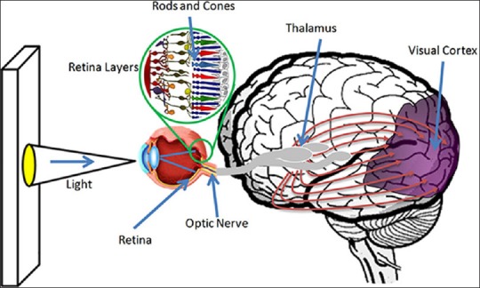
Human visual pathway.
It is worth mentioning that to develop a fully functional visual prosthesis, in addition to the development of electronics and hardware required for this purpose, engineers need to collaborate with specialists in clinical and surgical fields to form a multidisciplinary team. In addition to making decisions on main issues such as surgical and implantation procedures, the medical research team also works on the selection of appropriate types of lab animals, assesses and monitors issues related to the health and normal behavior of the subjects pre- and post-implantation, and on the design and development of clinical tests to assess the efficacy of the implant. In summary, to develop a visual prosthesis system for chronic operation, close collaboration between specialists in both engineering (designing circuits and systems, fabricating microstructures and signal processing) and medical disciplines is inevitable. Figure 2 illustrates the different design thrusts of a visual prosthesis microsystem.
Figure 2.
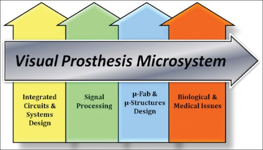
Visual prosthesis design thrusts.
In this review article, the general structure of a visual prosthesis is studied. Main building blocks of a typical visual prosthesis system are then briefly introduced. Some of the key design aspects at the system level as well as challenges faced in the development of such systems are subsequently addressed. Finally, the latest achievements in the design of visual prostheses by various research groups around the globe and some of their clinical test results will be reviewed.
VISUAL PROSTHESES, GENERAL DESIGN
Figure 3 shows the general architecture for visual prostheses of different kinds developed by several groups worldwide.[11,12,13,14,15,16] In a visual prosthesis system, an external video camera, usually worn on eyeglasses, captures images from the vision field of the patient in the outside world. Some external pre-processing is performed on recorded images in order to extract key image information and hence reduce the amount of data that will be transmitted to the implant. After retrieval of data on the implant side, an embedded processor sends the image information to a stimulation back-end, which is in charge of generating analog electrical pulses. Usually, a flexible cable conveys these electrical outputs to an electrode array that interfaces to the target tissue.
Figure 3.
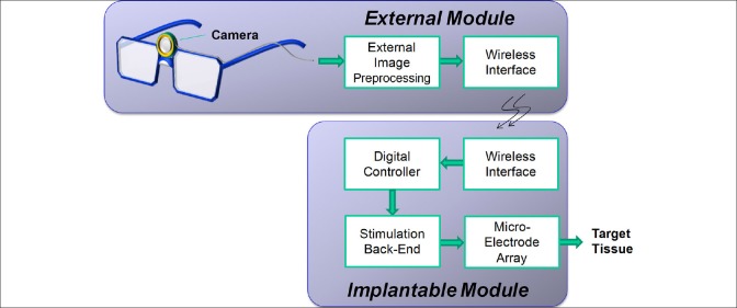
General architecture for different kinds of visual prosthesis systems developed by several groups actively involved in this research domain.
In the following subsections, a brief description of the aforementioned visual prosthesis electronic hardware units as well as some the associated design concerns are presented.
External Video Capture and Processing
The external module of a visual prosthesis consists of two parts: Video capture unit and image processing unit. As an inseparable part of any visual prosthesis system, the video capture unit comprises a miniaturized camera mounted on the patient's eyeglasses or head. Different types of cameras have been used for image and video capture, e.g. photodiode arrays,[16] charge-coupled devices (CCDs),[17] and complementary metal-oxide semiconductor (CMOS) cameras.[13,14] Due to the limited number of electrodes in the implant, image resolution of the camera does not impose any particular constraints on the image processing capability of the entire system. Temporal resolution is not expected to be a problem either, since the response of typical cameras is usually much faster than that of the human visual system.
The external unit of a visual prosthesis is usually powered by batteries and the implanted electronics receive power through wireless connection. Considering the fact that the implantable module is preferred to be realized with small physical size and operate with low power dissipation, any attempt to reduce circuit complexity and also power consumption of the implant is welcomed. For this reason, complex image processing tasks are usually performed right after capturing video information on the wearable external module where physical size and supplying electric power are not major concerns. Edge detection and image quality enhancement, zooming, contrast and brightness adjustment are among the image pre-processing tasks that are realized on the external side.[18] Image processing complexity depends on the type of techniques employed for enhancement of image quality and also on the part of the visual system being stimulated (i.e. retina, optic nerve, or the visual cortex).
The amount of data conveying the image captured from the outside world needs to be reduced in order to comply with some system-level restrictions and constraints such as wireless transmission bandwidth and processing capabilities of the implanted module. For this purpose, both resolution and color information of the image is lowered. Figure 4 shows a sample indoor picture, with different resolutions and gray levels.
Figure 4.

Various pixelized versions of different spatial resolutions with different gray levels.[20]
In image processing, in general, pixels are usually in the shape of small squares sitting by each other and forming a continuous picture. This is while, in visual prostheses, each pixel corresponds to a stimulating electrode. Patients undergoing electrical stimulation report visual sensations as a matrix of separate light spots. Therefore, to visualize what a patient carrying a visual prosthesis sees, it might be more meaningful to pixelize pictures with circular shapes rather than with square-shape pixels. The quality of vision restored using a visual prosthesis is highly dependent on the resolution of the image delivered to the visual system of the subject. This resolution is indeed defined by the number of stimulation sites on the target tissue. Simulations of prosthetic vision suggest that 600–1000 electrodes will be required to restore visual function to a level that would allow for reading, independent mobility, and facial recognition in retinal prostheses.[8]
Figure 5 shows two CMOS camera modules used as the external video capture device by one of the Iranian research groups (Research Laboratory for Integrated Circuits and Systems [ICAS], K. N. Toosi University of Technology, Tehran, Iran) in the field of visual prostheses.[19,20] These are both wearable hardware that can be used in dynamic tests to evaluate the image processing algorithms used in research prototypes and also in real visual prostheses.
Figure 5.

CMOS camera hardware used by ICAS visual prosthesis team (a) First generation,[19] (b) Second generation.[20]
Wireless Interface
Due to implant size limitations in visual prostheses and because of the necessity to avoiding wires to reduce the risk of infection, wireless operation of visual prostheses is inevitable. An inductive link between two closely-coupled coils is the most common approach to wirelessly send power and data from the external world to implantable biomedical devices.[21,22,23] In this approach, as shown in Figure 6a, a primary (transmitting) coil is placed on the outside and a secondary (receiving) coil is implanted inside the body with the thin layers of living tissues between them. Both sides of the link are tuned to the same resonant frequency, referred to as the carrier frequency. The wireless interface on the implant contains a power regulator and a data demodulator circuit for the retrieval of the received power and data, respectively.[24]
Figure 6.
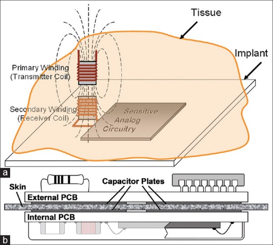
(a) Inductive coupling approach (b) Capacitive coupling approach.[25]
Recently, capacitive links have been proposed as novel alternatives which offer several advantages over their traditional counterparts, i.e. the inductive links [Figure 6b]. One of the most important advantages of the capacitive coupling approach is the high-pass nature of the link.[25,26] This is specifically welcomed in visual prostheses, where rather high data rates are required to enhance the quality of the images telemetered to the implant.
Besides size constrains, type of the wireless link and the high data rate, one of the most important issues in wireless telemetry is power dissipation in the human eye. This power dissipation may result in excessive temperature rise in biological tissues, which can lead to tissue damage. Therefore, when designing wireless interfaces, the amount of absorbed radio frequency (RF) energy has to be evaluated and compared with the human safety levels, usually expressed in terms of specific absorption rate (SAR) in associated standards.[27] Nowadays, SAR calculations are performed using high-resolution three-dimensional human body models by most electromagnetic simulators.[28,29]
Embedded Control Unit
Similar to almost any other implantable microstimulating systems, a visual prosthesis receives both setup and stimulation data from an external module. The implantable microsystem contains an embedded centralized controller, which is in charge of both administering the implant operation and generating stimulation commands/data. In general, system level specifications of the designed embedded controllers to be used in any kind of visual prostheses are the same. The stimulation data provided by the embedded controller are sent to a stimulation back-end, according to which appropriate stimulation pulses are generated and delivered to the target tissue. In fact, the embedded controller commands the microstimulator to generate electrical pulses with various amplitudes and pulse widths according to the data received from the external module. Other parameters such as inter-phase interval and stimulation period are also controlled by this block. Moreover, the embedded controller controls the sequence and order of stimulations for all the electrodes.
As the embedded controller is designed to be implanted inside the body, it needs to be realized with small physical dimensions, consume small amount of power, and utilize a limited bandwidth for data telemetry according to frequency allocation regulations. There are other concerns in the design of an embedded controller, which include interfacing with other modules of the system through minimum possible interconnects, and also operation with such a fast pace that allows the system to stimulate the natural visual system for real-time, flicker-free video streaming. This is why the research groups developing visual prosthesis systems prefer to design their own special-purpose controller[30,31] rather than using off-the-shelf commercially available, general purpose controllers.
Stimulation Circuitry
In a microstimulation system, analog stimulation pulses need to be generated according to the digital commands and data issued by the embedded controller. A stimulation back-end is in charge of generating and delivering electrical stimulation pulses to the target tissue. In electrical stimulation, stimulations can, in general, be in the form of current, voltage, or charge pulses. From the standpoint of the general form of the stimuli, both monophasic and biphasic pulses are used for stimulation. In monophasic stimulation, for each stimulation, a single pulse is generated to deliver a certain amount of electric current, charge, or voltage to the target tissue. In this case, one needs to consider provisions for discharging the stimulated area to avoid damage to the target tissue caused by charge accumulation. In charge-balanced biphasic stimulation [Figure 7], each stimulation pulse (anodic pulse) is followed by a pulse of reverse polarity (cathodic pulse) to collect charges delivered to the stimulated area by the anodic pulse. Amplitude and timing specifications of the stimulation pulses need to be tuned based on patient feedback on visual perception. Typical pulse amplitudes are within the 10–600 μA range, and the pulse widths range from 100 μs to around 2 ms. A typical delay of 0–1 ms is considered between the anodic and cathodic pulses, and pulse repetition rate for visual prostheses varies from 10 Hz to 125 Hz.[32]
Figure 7.
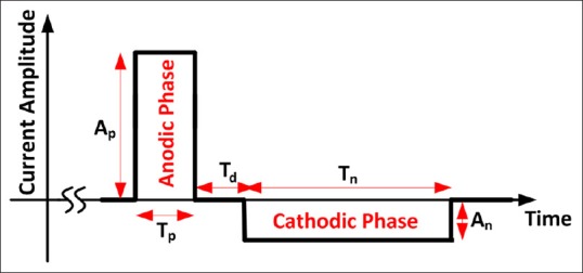
Diagram of biphasic current pulse in form of current.
It should be noted that, even in charge balanced biphasic stimulation, unavoidable systematic mismatches in the design and fabrication of the stimulation cause small residual charge at stimulation sites. Moreover, other issues such as charge leakage from adjacent stimulation sites over a period of time may result in the buildup of electric charge in the tissue being stimulated. Thus, charge cancellation circuitry is envisioned to periodically discharge stimulation sites by connecting the electrodes to the common ground potential.
Microelectrode Arrays
The advent of microelectrode arrays (MEAs) more than 20 years ago led to steady advancement in the development of neural interfaces as well as a meaningful progress in neuroscience research. The MEAs used in advanced neural and visual prosthesis microsystems comprise multiple electrode sites developed for chronic implantation.[33,34] Typically, an MEA is connected to the electronics platform using a ribbon cable containing multiple interconnects coated by or sandwiched in between flexible biocompatible polymeric protective layers [Figure 8]. However, the protective passivation layer, which is an insulator from the standpoint of electrical conduction, is removed from over the electrode sites in order to allow them to electrically interface with the target tissue. Silicon,[35] polyethylene terephthalate (PET),[36] polyimide,[37,38] and liquid crystal polymer[39] are among the materials used as the electrode substrate. Electrode sites are usually made of gold,[36] platinum,[40] and iridium-oxide.[41] High-temperature silicon oxide[42] and polymeric materials such as Parylene-C,[41] epoxy-based negative photoresist (SU-8)[36] and polydimethylsiloxane (PDMS)[43] are used for passivation.
Figure 8.
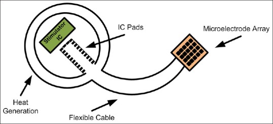
Stimulation microelectrode array.
In principle, the higher the number of stimulation sites are, the better the resolution will be. An immediate consequence of the increase in the number of channels is the increased complexity, size, and power dissipation of the system, none of which are desirable in visual prostheses.
DIFFERENT APPROACHES TO THE DEVELOPMENT OF VISUAL PROSTHESES
The visual pathway extends from photoreceptors in the retina to the visual cortex in the brain. Conceptually, to realize a visual prosthesis, the image information recorded from the external world can be delivered to the natural visual system at any point along this path (of course, provided that from there on, the rest of the system is healthy and functioning). Hence, several approaches are taken to restore vision to the blind, which can be categorized into: Stimulation of the retina, optic nerve stimulation, and cortical stimulation. Each one of these approaches has its own attraction. One of the key reasons, on the engineering side, for the great interest directed towards retinal approaches is to maximally benefit from the image processing performed in the natural visual system, hence reducing the extent of the image processing expected from the visual prosthesis. Optic nerve stimulation is an attempt to deliver image information to the natural visual system at the very first place after the retina. This approach can be a possible option when the retina is atrophied. The cortical approach is also considered as one of the possible candidates, trying to bypass the visual pathway all the way to the visual cortex.
Retinal Prosthesis
It has been shown that electrical stimulation of retinal bipolar and ganglion cells yields visual sensation. Therefore, a retinal implant for patients suffering from RP and AMD seems to be feasible.[8,11,12,16] There are two main approaches to stimulate retinal ganglion cells: (I) Epi-retinal stimulation, in which, the prosthetic device is attached to the inner retinal surface; and (II) the sub-retinal approach, which involves implanting an electrode array between bipolar cells and the retinal pigment epithelium[11,12] [Figure 9]. In both approaches, generally, power and information are delivered to the electrode array from a separating processing unit. While the electrode array needs to be attached to a certain area in the retina, factors such as surgical detail, length of interconnections between the electrode array and the implanted electronic package, and thermal safety considerations determine where the electronics platform will be placed.[11,12]
Figure 9.
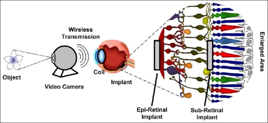
Retinal visual prosthesis.
A number of retinal prosthesis projects are being pursued through both epi-retinal and sub-retinal approaches. The advantages of the epi-retinal approach include the following: (1) The procedure for implantation is relatively straightforward and placement on the epi-retinal surface will not separate the retina from retinal pigment epithelium and choroid. (2) Epi-retinal placement allows for the vitreous to act as a sink for heat dissipation from the microelectronic device.[44,45] Disadvantages of this approach include: (1) Requirement of techniques that will provide prolonged attachment of the device to the inner retina on the medical side,[46,47] and (2) stimulation at the output of the retina (ganglion cells) on the engineering side, which will require more sophisticated image processing to account for retina algorithms.[48]
Placement of the prosthesis in the sub-retinal space has advantages such as closer proximity to the next surviving layers of neurons in the visual pathway (i.e. bipolar cells).[49,50] Stimulation at the bipolar cell level will allow significant retinal processing to shape the neural response. Placing an electrode interface in the sub-retinal space will use the retina to hold the electrode in close proximity to the electrode.[49] Also, fixation of an implant in the sub-retinal space might be more stable than tacking it to the epi-retinal surface. Disadvantages of this approach include the limited sub-retinal space to place the electronics as well as the close proximity of the retina to the electronics which would increase the likelihood of thermal injury to neurons and consequently limit the thermal budget of the implant. If the sub-retinal implant is only an electrode array with the electronics outside the eye, then the implant will have a cable across the sclera, which may result in a tethering effect on the cable.[51] Furthermore, this cable, over the long term, increases the likelihood of sub-retinal hemorrhage and total or local retinal detachment.
There is another sub-retinal approach, in which a microchip containing photodiode arrays is implanted under the transparent retina to substitute the degenerated photoreceptors. The implant is, indeed, a single component in charge of converting incident light to electrical current and delivering the resulting electrical stimuli to the retina.[16] While all of the approaches on the development of visual prostheses require external image and data processing due to bypassing retinal image analysis, implantable photodiode arrays are intended to replace the function of degenerated photoreceptors by directly translating the image into small electrical stimulations with no need for additional electronic circuitry. Other advantages of this approach include easy placement, fewer components, and since no video camera is used, the possibility of using eye movement to locate objects. In its original form, the principal drawback of this system is the inability of the photodiodes to generate strong enough currents to stimulate the adjacent neurons by using merely the incident light. Also, placement of the photodiode array component could damage the retina through pigment epithelium separation or obstruction of blood flow from the retina.
Optic Nerve Stimulation
The optic nerve, which is about 1–2 mm in diameter, serves as a compact conduit for all the information in the visual scene. This means that electrical stimulation of a small area of the optic nerve would be expected to activate a large segment of the visual field. Stimulation of the optic nerve is realized using a cuff electrode encircling it, as illustrated in Figure 10. Since the electrodes are on the outside of a very densely packed nerve (~1.2 million fibers within the nerve), focal stimulation and detailed perception are difficult to achieve.[52] This approach also requires real-time image capture and processing, and also a telemetry link for the transfer of power and data to the electronic implant. As a result of completely bypassing the retina, not only this approach can be used for patients with retinal degeneration, it also offers a relatively safer and easier implantation procedure compared to retinal approaches. This approach is, however, rather immature compared to its counterparts. The possibility of generating pattern vision by eliciting spatially adjacent phosphenes using optic nerve stimulation is still unclear.[53]
Figure 10.
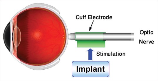
Optic nerve stimulation.
The Cortical Approach
Historically, there has been notable research in the development of a visual prosthesis that stimulates the visual cortex. Starting in the 1960’s, several reports were released on the induction of phosphenes in patients with profound blindness.[54,55] Patients reported the ability to read Braille patterns, real letters, drive a car in a parking lot, and walk around a room using this kind of prostheses.[56,57,58]
Without taking so many technological, surgical, and cognitive challenges into consideration, stimulation of the visual cortex [Figure 11] is believed to be successful in restoration of vision for the blind due to different causes, including those suffering from damage to both the retina and optic nerve. However, for those who are eligible to use retinal prosthesis or optic nerve stimulation, cortical visual prostheses might not be the first choice. The rather high surgical risk that a patient with an otherwise healthy brain needs to take, and also the extra complicated image processing that the artificial system needs to handle are among the reasons why the cortical approach has not been welcomed as compared with other approaches.[7,10,59,60,61,62] Among the significant advantages of the cortical approach over its counterparts, one can point to the reduced power requirements per stimulation site, more predictable phosphene generation, less phosphene interaction, absence of flicker, and the possibility of packing more stimulation channels thereby increasing resolution.[63]
Figure 11.
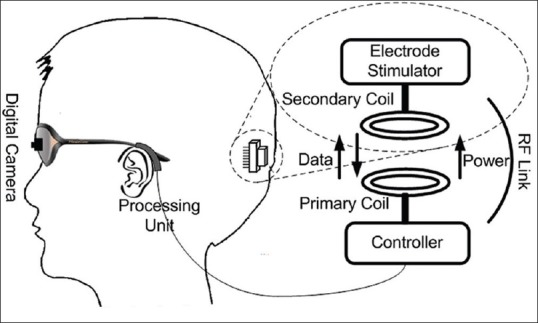
Cortical approach.
VISUAL PROSTHESES PIONEERING RESEARCH GROUPS
Over the past decade, several research teams have been involved in the development of functioning visual prostheses. Based on a search within Elsevier's Scopus database, Figure 12 shows the exponential-like growth of scientific and technical documents published on ‘visual’ and ‘prosthesis’ over the past decades. Contribution of pioneer countries in the field of visual prostheses, in terms of papers published during 2008–2013[64] is illustrated in Figure 13. More than 55% of these publications are in the field of medicine.[64]
Figure 12.
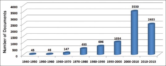
Number of scientific and technical documents published with the keywords ‘visual’ and “prosthesis” in their titles or abstracts.
Figure 13.
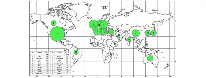
Contribution of the countries actively involved in research on visual prostheses in terms of the number of papers they published during 2008–2013.
The Artificial Retina team is one of the pioneer groups in the development of implantable visual prostheses. Professors M. Humayun and E. DeJuan of the Doheny Eye Institute at the University of Southern California (USC), Dr. R. Greenberg of Second Sight company, and Professor W. Liu of the University of California at Santa Cruz (UCSC) are the original inventors of the active epi-retinal prosthesis. They demonstrated proof of principle in acute patient investigations at Johns Hopkins University in the early 1990s. In the late 1990s, the company Second Sight was formed by Dr. Greenberg along with medical device entrepreneur, A. Mann, to develop a chronically implantable retinal prosthesis. Their first generation implant had 16 electrodes and was implanted in 6 subjects between 2002 and 2004. These subjects, who were all completely blind prior to implantation, could perform a surprising array of tasks using the device.[7] In 2007, Second Sight began a trial of its second generation 60-electrode implant, named Argus II, in the U.S. and Europe. In total, 30 subjects participated in the studies spanning 10 sites in 4 countries. The preliminary results show that the Argus II system provides some functional vision to blind subjects.[59] In the spring of 2011, after more than two decades of research and development in the field of visual prosthesis, Argus II was approved for clinical and commercial use in Switzerland, France, and the UK.[65] Second Sight Company launched the product later the same year. Three major U.S. government funding agencies (National Eye Institute, Department of Energy, and National Science Foundation) have supported the work at Second Sight Company, USC, UCSC, CalTech, and other research laboratories.[7]
To date, Second Sight has sponsored clinical tests approved by the US Food and Drug Administration (FDA) for the Argus I and II model systems. The Argus II retinal implant was successfully implanted in 2013 in two patients suffering from RP in Saudi Arabia. The patients were one man and one woman and had the Argus II retinal prosthesis system implanted in one eye. Average length of surgery was 3 h. Now, the patients can recognize the presence of people in front of them and are able to detect buildings outside, as well as flowers in grass areas.[7] As research on the implant progresses, upgraded performance for the processing of visual information are expected in the future. The Second Sight Company expects future upgraded models to give patients the ability to see faces, color and also night vision.[7] The next step of the Argus project is to produce a 256-electrode device ready for extensive preclinical testing.[11] Their new design has a highly compact array and this array is four times more densely packed with metal contact electrodes than that of the Argus II.[11] Simulations and calculations indicate that the 256 electrode device should provide improved vision for patients. Interested readers are referred to the latest news published by the Second Sight Company's website for more information and also clinical studies.[7]
The Boston Retinal Implant (USA) is involved in the development of a sub-retinal visual prosthesis. Their miniaturized, hermetically-encased, wirelessly-operated retinal prosthesis has been developed for preclinical studies in a Yucatan minipig. The implant part of this system attaches to the outer surface of the eye and electrically drives a microfabricated thin film polyimide array of sputtered iridium oxide film electrodes. This array is implanted into the sub-retinal space using a customized ab externo surgical technique. The implanted device includes a hermetic titanium case containing a 15-channel stimulator chip as well as some discrete circuit components. The operation of this implant has been verified in two pigs for up to 5½ months by detecting stimulus artifacts generated by the implanted device.[12,60]
C-Sight (Chinese Project for Sight) is a multidisciplinary research project on visual prosthesis founded in China. The goal of the C-Sight project is to develop an implantable optic nerve stimulation microelectronic medical device that will restore vision to a limited extent to the blind. In their approach, they couple the encoded electrical stimuli into axons of ganglion cells by penetrating multi-electrode arrays into the optic nerve. Feasibility of this approach has been studied using animal experiments.[13,66]
As an example of cortical visual prosthesis, one can name the system developed by the Dobelle Institute under direction of William Dobelle (1941–2004). In this work, visual information are transcutaneously transferred from an external image capture and preprocessing unit to an implanted 64-electrode array. The patient carrying this prosthesis was able to read two inch tall letters at a distance of five feet, representing a visual acuity of about 20/400. Although the electrode array produces tunnel vision, the subject was able to navigate in unfamiliar environments.[54]
While all of the above mentioned approaches work on the same basic concept illustrated in Figure 3, the Retina Implant group in Germany tries to restore vision using a subretinal microphotodiode array. In the first clinical pilot study, the array was implanted in 11 patients suffering from photoreceptor degeneration. In one subject, whose implant was placed under the macula, visual acuity of 20/1000 was reported. The results of this study demonstrated, for the first time, that sub-retinal microelectrode arrays with 1,500 photodiodes can create detailed meaningful visual perception.[10,16] In another study, the photodiodes were implanted in 9 blind patients. The patients received the subretinal visual implant in one eye and the other eye was always occluded during the tests. None of the subjects had other eye diseases that might affect the visual pathway. In this study, visual acuity measurement with Landolt C-rings up to Snellen visual acuity of 20/546 (corresponding to decimal 0.037 or corresponding to 1.43 logMAR [minimum angle of resolution]) were restored via the subretinal implant.[67] Light perception, light localization and motion detection tests were also performed on the subjects. This study has shown that the designed system can restore useful vision in daily life for at least two-thirds of the blind patients investigated.
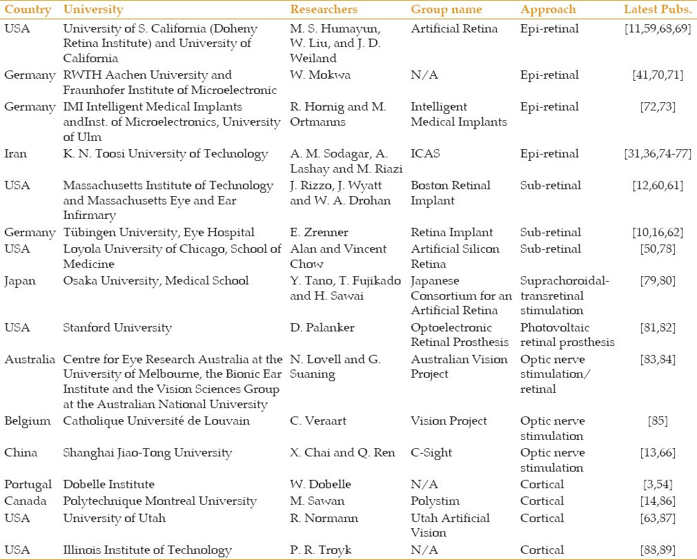
A brief overview of current artificial vision projects is presented in Table 1. Interested readers are referred to the latest papers published by each research group for more information.
Table 1.
Brief overview of current artificial vision projects around the world
SUMMARY
A review of the visual prostheses intended to restore functional vision is provided herein. Basic concepts in research on these implantable microsystems are studied, and general issues in their design and development are discussed. Different types of visual prostheses, from the standpoint of how they work and how they are used, are introduced. Subsequently, latest achievements in the design of visual prostheses by pioneer research groups and companies around the globe and some of their clinical test results are briefly reviewed.
ACKNOWLEDGMENTS
The authors would like to thank the ICAS visual prosthesis team members: M. A. Shahzeidi, A. Shaker, H. Salehi, L. Saadati-fard, S. Novin, M. Takhti, E. Ashoori, and F. Asgarian for their technical contribution; S. Sharafzadeh and Z. Erfani-Gholampour for their assistance in artwork and computer graphics; and also A. Sheikholeslami, J. Maghami, and F. Khosravi for their help and support.
Footnotes
Source of Support: Nil.
Conflict of Interest: None declared.
REFERENCES
- 1.Prochazka A, Mushahwar VK, McCreery DB. Neural prostheses. J Physiol. 2001;533(Pt 1):99–109. doi: 10.1111/j.1469-7793.2001.0099b.x. [DOI] [PMC free article] [PubMed] [Google Scholar]
- 2.Zeng FG, Rebscher S, Harrison W, Sun X, Feng H. Cochlear implants: System design, integration, and evaluation. IEEE Rev Biomed Eng. 2008;1:115–142. doi: 10.1109/RBME.2008.2008250. [DOI] [PMC free article] [PubMed] [Google Scholar]
- 3.Dobelle WH. Artificial vision for the blind by connecting a television camera to the visual cortex. ASAIO J. 2000;46:3–9. doi: 10.1097/00002480-200001000-00002. [DOI] [PubMed] [Google Scholar]
- 4.Fodstad H, Hariz M. Electricity in the treatment of nervous system disease. In: Sakas DE, Simpson BA, Krames ES, editors. Operative Neuromodulation: Functional Neuroprosthetic Surgery. Vol. 1. Vienna: Springer; 2007. pp. 11–19. [Google Scholar]
- 5.Sekirnjak C, Hottowy P, Sher A, Dabrowski W, Litke AM, Chichilnisky EJ. High-resolution electrical stimulation of primate retina for epiretinal implant design. J Neurosci. 2008;28:4446–4456. doi: 10.1523/JNEUROSCI.5138-07.2008. [DOI] [PMC free article] [PubMed] [Google Scholar]
- 6.Margalit E, Maia M, Weiland JD, Greenberg RJ, Fujii GY, Torres G, et al. Retinal prosthesis for the blind. Surv Ophthalmol. 2002;47:335–356. doi: 10.1016/s0039-6257(02)00311-9. [DOI] [PubMed] [Google Scholar]
- 7.Second Sight Company. [Last accessed on 2013 Nov 30]. Available from: http://www.2-sight.eu/ee/home-ee .
- 8.Weiland JD, Humayun MS. Visual prosthesis. Proc IEEE Inst Electr Electron Eng. 2008;96:1076–1084. [Google Scholar]
- 9.Humayun MS, Dorn JD, da Cruz L, Dagnelie G, Sahel JA, Stanga PE, et al. Interim results from the international trial of Second Sight's visual prosthesis. Ophthalmology. 2012;119:779–788. doi: 10.1016/j.ophtha.2011.09.028. [DOI] [PMC free article] [PubMed] [Google Scholar]
- 10.Electronic supplementary material to the publication of E. Zrenner et al. Subretinal electronic chips allow blind patients to read letters and combine them to words. Proc R Soc B. 2011;278:1489–1497. doi: 10.1098/rspb.2010.1747. Available from: URL: http://dx.doi.org/10.1098/rspb.2010.1747 . [DOI] [PMC free article] [PubMed] [Google Scholar]
- 11.Chen K, Yang Z, Hoang L, Weiland JD, Humayun MS, Liu W. An Integrated 256-Channel Epiretinal Prosthesis. IEEE J Solid-State Circuits. 2010;45:1946–1956. [Google Scholar]
- 12.Shire DB, Kelly SK, Chen J, Doyle P, Gingerich MD, Cogan SF, et al. Development and implantation of a minimally invasive wireless subretinal neurostimulator. IEEE Trans Biomed Eng. 2009;56:2502–2511. doi: 10.1109/TBME.2009.2021401. [DOI] [PMC free article] [PubMed] [Google Scholar]
- 13.Chai X, Li L, Wu K, Zhou C, Cao P, Ren Q. C-sight visual prostheses for the blind. IEEE Eng Med Biol Mag. 2008;27:20–28. doi: 10.1109/MEMB.2008.923959. [DOI] [PubMed] [Google Scholar]
- 14.Sawan M, Trepanier A, Trepanier JL, Audet Y, Ghannoum R. A New CMOS multimode digital pixel sensor dedicated to an implantable visual cortical stimulator. Analog Integr Circuits Signal Process. 2006;49:187–197. [Google Scholar]
- 15.Coulombe J, Sawan M, Gervais JF. A highly flexible system for microstimulation of the visual cortex: Design and implementation. IEEE Trans Biomed Circuits Syst. 2007;1:258–269. doi: 10.1109/TBCAS.2007.916026. [DOI] [PubMed] [Google Scholar]
- 16.Zrenner E, Bartz-Schmidt KU, Benav H, Besch D, Bruckmann A, Gabel VP, et al. Subretinal electronic chips allow blind patients to read letters and combine them to words. Proc Biol Sci. 2011;278:1489–1497. doi: 10.1098/rspb.2010.1747. [DOI] [PMC free article] [PubMed] [Google Scholar]
- 17.Harvey J-F, Sawan M. Vol. 1. Amsterdam, Netherlands, October 31- November 3: Proc of the Annual International Conference of the IEEE EMBS (EMBC); 1996. Image Acquisition and Reduction Dedicated to a Visual Implant; pp. 403–404. [Google Scholar]
- 18.Boyle J. PhD Dissertation. Queensland University of Technology; 2005. Improving Perception from Electronic Visual Prostheses. [Google Scholar]
- 19.Shahzeidi MA. MSc Dissertation. K. N. Toosi University of Technology; 2010. Video Image Capturing, Processing and Preparation for an Implantable Visual Prosthesis. [Google Scholar]
- 20.Shaker A. M.Sc. Dissertation Shahid Rajaee Teacher Training University; 2011. Image Capture and Processing to be Used in Visual Prostheses. [Google Scholar]
- 21.Hu Y, Sawan M, El-Gamal M. An integrated power recovery module dedicated to implantable electronic devices. Analog Integr Circuits Signal Process. 2005;43:171–181. [Google Scholar]
- 22.Sodagar AM, Najafi K. San Juan, Puerto Rico: Proc of the IEEE International Midwest Symposium on Circuits and Systems (MWSCAS); 2006. Wireless Interfaces for Implantable Biomedical Microsystems; pp. 265–269. [Google Scholar]
- 23.Lehmann T, Chun H, Yang Y. Power saving circuit design techniques for implantable neuro-stimulators. J Circuits Syst Comput. 2012;21:1–14. [Google Scholar]
- 24.Asgarian F, Sodagar AM. Wireless telemetry for implantable biomedical microsystems. In: Laskovski AN, editor. Biomedical Engineering, Trends in Electronics, Communications and Software. Rijeka: InTech; 2011. pp. 21–44. [Google Scholar]
- 25.Sodagar AM, Amiri P. Antalya, Turkey, April 29-May 2: Proc of the International IEEE/EMBS Conference on Neural Engineering (NER); 2009. Capacitive Coupling for Power and Data Telemetry to Implantable Biomedical Microsystems; pp. 411–414. [Google Scholar]
- 26.Takhti M, Asgarian F, Sodagar AM. San Diego, California, USA, November 10-12: Proc of the IEEE Biomedical Circuits and Systems Conference (BioCAS); 2011. Modeling of a Capacitive Link for Data Telemetry to Biomedical Implants; pp. 181–184. [Google Scholar]
- 27.IEEE Standard C95.1-2005. IEEE Standards for Safety Levels with Respect to Human Exposure to Radio Frequency Electromagnetic Fields, 3 KHz to 300 GHz. [Last accessed on 2013 Nov 20]. Available from: http://standards.ieee.org/findstds/standard/C95.1-2005.html .
- 28.Dimbylow P. Development of the female voxel phantom, NAOMI, and its application to calculations of induced current densities and electric fields from applied low frequency magnetic and electric fields. Phys Med Biol. 2005;50:1047–1070. doi: 10.1088/0031-9155/50/6/002. [DOI] [PubMed] [Google Scholar]
- 29.Christ A, Kainz W, Hahn EG, Honegger K, Zefferer M, Neufeld E, et al. The Virtual Family - Development of surface-based anatomical models of two adults and two children for dosimetric simulations. Phys Med Biol. 2010;55:N23–38. doi: 10.1088/0031-9155/55/2/N01. [DOI] [PubMed] [Google Scholar]
- 30.Talukder MI, Siy P, Auner GW. High resolution implantable microsystem and probe design for retinal prosthesis. Open Ophthalmol J. 2008;2:77–90. doi: 10.2174/1874364100802010077. [DOI] [PMC free article] [PubMed] [Google Scholar]
- 31.Salehi H, Sodagar AM. Mexico, March 14-17: Proc of the IEEE International Caribbean Conference on Devices, Circuits, and Systems (ICCDCS), Playa del Carmen; 2012. Design of an Application-Specific Controller for a Visual Prosthesis; pp. 1–4. [Google Scholar]
- 32.Auner GW, You R, Siy P, McAllister JP, Talukder M, Abrams GW. Development of a wireless high. frequency microarray implant for retinal stimulation. In: Humayun MS, Weiland JD, Chader G, Greenbaum E, editors. Artificial Sight: Basic Research, Biomedical Engineering, and Clinical Advances. New York: Springer; 2007. pp. 169–186. [Google Scholar]
- 33.Mohseni P, Najafi K. Vol. 1. San Francisco, CA, USA, February 10: Proc of the IEEE International Solid-State Circuits Conference, Digest of Technical Papers (ISSCC); 2005. A Battery-Powered 8-Channel Wireless FM IC for Biopotential Recording Applications; pp. 560–617. [Google Scholar]
- 34.Harrison RR, Watkins PT, Kier RJ, Lovejoy RO, Black DJ, Greger B, et al. A low-power integrated circuit for a wireless 100-electrode neural recording system. IEEE J Solid State Circuits. 2007;42:123–133. [Google Scholar]
- 35.Normann RA, Capmbell PK, Jones KE. Nara January 30 - February 2: Proc of the IEEE MEMS Conference; 1991. Micromachined, Silicon Based Electrode Arrays for Electrical Stimulation of or Recording from Cerebral Cortex; pp. 247–252. [Google Scholar]
- 36.Ahani A, Saadati-Fard L, Sodagar AM, Boroumad FA. Boston, Massachusetts, USA, August 30 - September 3: Proc of the Annual International Conference of the IEEE EMBS (EMBC); 2011. Flexible PET/ITO Electrode Array for Implantable Biomedical Applications; pp. 2878–2881. [DOI] [PubMed] [Google Scholar]
- 37.Johnson LJ, Scribner DA. Electrode architecture meeting the challenge of the retina-electrode interface. In: Rizzo J, Tombran-Tink J, Barnstable CJ, editors. Visual Prosthesis and Ophthalmic Devices: New Hope in Sight. Totowa, NJ: Humana Press Inc; 2007. pp. 121–133. [Google Scholar]
- 38.Sui X, Sun J, Li L, Zhou C, Luo X, Xia N, et al. Evaluation of a MEMS-based dual metal-layer thin-film microelectrode array for suprachoroidal electrical stimulation. IEEE Trans Neural Syst Rehabil Eng. 2013;21:524–531. doi: 10.1109/TNSRE.2012.2188042. [DOI] [PubMed] [Google Scholar]
- 39.Lee SE, Jun SB, Lee HJ, Kim J, Lee SW, Im C, et al. A flexible depth probe using liquid crystal polymer. IEEE Trans Biomed Eng. 2012;59:2085–2094. doi: 10.1109/TBME.2012.2196274. [DOI] [PubMed] [Google Scholar]
- 40.Weiland JD, Humayun MS, Eckhardt H, Ufer S, Laude L, Basinger B, et al. Minneapolis, Minnesota, USA, September 2-6: Proc of the Annual International Conference of the IEEE EMBS (EMBC); 2009. A Comparison of Retinal Prosthesis Electrode Array Substrate Materials; pp. 4140–4143. [DOI] [PubMed] [Google Scholar]
- 41.Mokwa W, Goertz M, Koch C, Krisch I, Trieu H-K, Walter P. Vancouver, British Columbia, Canada, August 20-24: Proc of the Annual International IEEE EMBS Conference (EMBC); 2008. Intraocular Epiretinal Prosthesis to Restore Vision in Blind Humans; pp. 5790–5793. [DOI] [PubMed] [Google Scholar]
- 42.Wang K, Deurzen M, Kooyman N, Decré MMJ. Minneapolis, Minnesota, USA, September 2-6: Proc of the Annual International Conference of the IEEE EMBS (EMBC); 2009. Towards Circuit Integration on Fully Flexible Parylene Substrates; pp. 5866–5869. [DOI] [PubMed] [Google Scholar]
- 43.Minev IR, Chew DJ, Delivopoulos E, Fawcett JW, Lacour SP. Cancun, Mexico, April 27-May 1: Proc of the International IEEE EMBS Conference on Neural Engineering (NER); 2011. Evaluation of an Elastomer Based Gold Microelectrode Array for Neural Recording Applications; pp. 482–485. [Google Scholar]
- 44.Piyathaisere DV, Margalit E, Chen SJ, Shyu JS, D’Anna SA, Weiland JD, et al. Heat effects on the retina. Ophthalmic Surg Lasers Imaging. 2003;34:114–120. [PubMed] [Google Scholar]
- 45.Gosalia K, Weiland J, Humayun M, Lazzi G. Thermal elevation in the human eye and head due to the operation of a retinal prosthesis. IEEE Trans Biomed Eng. 2004;51:1469–1477. doi: 10.1109/TBME.2004.827548. [DOI] [PubMed] [Google Scholar]
- 46.Majji AB, Humayun MS, Weiland JD, Suzuki S, D’Anna SA, de Juan E., Jr Long-term histological and electrophysiological results of an inactive epiretinal electrode array implantation in dogs. Invest Ophthalmol Vis Sci. 1999;40:2073–2081. [PubMed] [Google Scholar]
- 47.Walter P, Szurman P, Vobig M, Berk H, Lüdtke-Handjery HC, Richter H, et al. Successful long-term implantation of electrically inactive epiretinal microelectrode arrays in rabbits. Retina. 1999;19:546–552. doi: 10.1097/00006982-199911000-00012. [DOI] [PubMed] [Google Scholar]
- 48.Becker M, Eckmiller R, Hunerman R. Psychophysical test of tunable retina encoder for retinal implants. IEEE J Neural Netw. 1999;1:192–195. [Google Scholar]
- 49.Völker M, Shinoda K, Sachs H, Gmeiner H, Schwarz T, Kohler K, et al. In vivo assessment of subretinally implanted microphotodiode arrays in cats by optical coherence tomography and fluorescein angiography. Graefes Arch Clin Exp Ophthalmol. 2004;242:792–799. doi: 10.1007/s00417-004-0935-6. [DOI] [PubMed] [Google Scholar]
- 50.Chow AY, Chow VY, Packo KH, Pollack JS, Peyman GA, Schuchard R. The artificial silicon retina microchip for the treatment of vision loss from retinitis pigmentosa. Arch Ophthalmol. 2004;122:460–469. doi: 10.1001/archopht.122.4.460. [DOI] [PubMed] [Google Scholar]
- 51.Gekeler F, Kobuch K, Schwahn HN, Stett A, Shinoda K, Zrenner E. Subretinal electrical stimulation of the rabbit retina with acutely implanted electrode arrays. Graefes Arch Clin Exp Ophthalmol. 2004;242:587–596. doi: 10.1007/s00417-004-0862-6. [DOI] [PubMed] [Google Scholar]
- 52.Margalit E, Sadda SR. Retinal and optic nerve diseases. Artif Organs. 2003;27:963–974. doi: 10.1046/j.1525-1594.2003.07304.x. [DOI] [PubMed] [Google Scholar]
- 53.Cohen ED. Prosthetic interfaces with the visual system: Biological issues. J Neural Eng. 2007;4:R14–31. doi: 10.1088/1741-2560/4/2/R02. [DOI] [PubMed] [Google Scholar]
- 54.Dobelle WH, Mladejovsky MG, Girvin JP. Artifical vision for the blind: Electrical stimulation of visual cortex offers hope for a functional prosthesis. Science. 1974;183:440–444. doi: 10.1126/science.183.4123.440. [DOI] [PubMed] [Google Scholar]
- 55.Button J, Puttnam T. Visual responses to cortical stimulation in the blind. J Lowa Med Soc. 1962;52:17–21. [Google Scholar]
- 56.Brindley GS, Lewin WS. The sensations produced by electrical stimulation of the visual cortex. J Physiol. 1968;196:479–493. doi: 10.1113/jphysiol.1968.sp008519. [DOI] [PMC free article] [PubMed] [Google Scholar]
- 57.Brindley GS. Effects of electrical stimulation of the visual cortex. Hum Neurobiol. 1982;1:281–283. [PubMed] [Google Scholar]
- 58.Brindley G, Rushton D. Implanted stimulators of the visual cortex as visual prosthetic devices. Trans Am Acad Ophthalmol Otolaryngol. 1974;78:741–745. [Google Scholar]
- 59.Humayun MS, Dorn JD, Ahuja AK, Caspi A, Filley E, Dagnelie G, et al. Minneapolis, Minnesota, USA, September 2-6: Proc of the Annual International Conference of the IEEE EMBS (EMBC); 2009. Preliminary 6 Month Results from the Argus II Epiretinal Prosthesis Feasibility Study; pp. 4566–4568. [DOI] [PMC free article] [PubMed] [Google Scholar]
- 60.Kelly SK, Shire DB, Chen J, Doyle P, Gingerich MD, Cogan SF, et al. A hermetic wireless subretinal neurostimulator for vision prostheses. IEEE Trans Biomed Eng. 2011;58:3197–31205. doi: 10.1109/TBME.2011.2165713. [DOI] [PMC free article] [PubMed] [Google Scholar]
- 61.Kelly S, Shire DB, Chen J, Gingerich MD, Cogan SF, Drohan WA, et al. San Jose, California, USA, July 15-19: Proc of the IEEE International Conference on Multimedia and Expo Workshops (ICMEW); 2013. Developments on the Boston 256-Channel Retinal Implant; pp. 1–6. [Google Scholar]
- 62.Peters T, Klingberg S, Zrenner E, Wilhelm B. Emotional wellbeing of blind patients in a pilot trial with subretinal implants. Graefes Arch Clin Exp Ophthalmol. 2013;251:1489–1493. doi: 10.1007/s00417-012-2210-6. [DOI] [PubMed] [Google Scholar]
- 63.Normann RA, Maynard EM, Guillory KS, Warren DJ. Cortical implants for the blind. IEEE Spectr. 1996;33:54–59. [Google Scholar]
- 64.Based on a Search in Elsevier's Scopus Data Base with Keyword (‘visual’ AND ‘prosthesis’) in Title, Abstract, or Keywords. [Last accessed on 2014 Mar 03]. Available from: http://www.scopus.com .
- 65.A Bionic Eye Comes to Market. MIT Technology Review; 7 March. 2011. [Last accessed on 2013 Nov 30]. Available from: http://www.technologyreview.com/news/423216/a-bionic-eye-comes-to-market .
- 66.Lu Y, Yan Y, Chai X, Ren Q, Chen Y, Li L. Electrical stimulation with a penetrating optic nerve electrode array elicits visuotopic cortical responses in cats. J Neural Eng. 2013;10:036022. doi: 10.1088/1741-2560/10/3/036022. [DOI] [PubMed] [Google Scholar]
- 67.Stingl K, Bartz-Schmidt KU, Besch D, Braun A, Bruckmann A, Gekeler F, et al. Artificial Vision with Wirelessly Powered Subretinal Electronic Implant Alpha-IMS. Proc Biol Sci. 2013;280:20130077. doi: 10.1098/rspb.2013.0077. 1:8. [DOI] [PMC free article] [PubMed] [Google Scholar]
- 68.Chen K, Lo YK, Yang Z, Weiland JD, Humayun MS, Liu W. A system verification platform for high-density epiretinal prostheses. IEEE Trans Biomed Circuits Syst. 2013;7:326–37. doi: 10.1109/TBCAS.2012.2200103. [DOI] [PubMed] [Google Scholar]
- 69.Zhou DD, Dorn JD, Greenberg RJ. San Jose, California, USA, July 15-19: Proc of the IEEE International Conference on Multimedia and Expo Workshops (ICMEW); 2013. The Argus II Retinal Prosthesis System: An Overview; pp. 1–6. [Google Scholar]
- 70.Schwarz M, Ewe L, Hijazi N, Hosticka BJ, Huppertz J, Kolnsberg S, et al. Lyon, France, October 12-14: Proc of the Annual International IEEE-EMBS Special Topic Conference on Microtechnologies, Medicine & Biology; 2000. Micro Implantable Visual Prostheses; pp. 461–465. [Google Scholar]
- 71.Winkin N, Mokwa W. San Diego, CA, USA, August 28 - September 1: Proc of the Annual International Conference of the IEEE EMBS (EMBC); 2012. Flexible Multi-Electrode Array with Integrated Bendable CMOS-Chip for Implantable Systems; pp. 3882–3885. [DOI] [PubMed] [Google Scholar]
- 72.Hornig R, Zehnder T, Velikay-Parel M, Laube T, Feucht M, Richard G. The IMI retinal implant system. In: Humayun MS, Weiland JD, Chader G, Greenbaum E, editors. Artificial Sight: Basic Research, Biomedical Engineering, and Clinical Advances. New York: Springer; 2007. pp. 111–128. [Google Scholar]
- 73.Noorsal E, Sooksood K, Xu H, Hornig R, Becker J, Ortmanns M. A neural stimulator frontend with high-voltage compliance and programmable pulse shape for epiretinal implants. IEEE J Solid State Circuits. 2012;47:244–256. [Google Scholar]
- 74.Razmpour S, Sodagar AM, Faizollah M, Darmani MY, Nourian M. Beijing, China, May 19-23: Proc of the IEEE International Symposium on Circuits and Systems (ISCAS); 2013. Reconfigurable Biological Signal Co-Processor for Feature Extraction Dedicated to Implantable Biomedical Microsystems; pp. 861–864. [Google Scholar]
- 75.Zabihian AR, Maghami MH, Asgarian F, Sodagar AM. Implantable biomedical devices. In: Hudak R, Penhaker M, Majernik J, editors. Biomedical Engineering, Technical Applications in Medicine. Rijeka: InTech; 2012. pp. 157–190. [Google Scholar]
- 76.Maghami MH, Sodagar AM, Sawan M. Melbourne, Australia, June1-5: Proc of the IEEE International Symposium on Circuits and Systems (ISCAS); 2014. Biphasic, Energy-Efficient, Current-Controlled Stimulation Back-End for Retinal Visual Prosthesis; pp. 241–244. [Google Scholar]
- 77.Karimi M, Maghami MH, Faizollah M, Sodagar AM. Lausanne, Switzerland, October 22-24: Proc of the IEEE Biomedical Circuits and Systems Conference (BioCAS); 2014. A Noncoherent Low-Power High-Data-Rate BPSK Demodulator and Clock Recovery Circuit for Implantable Biomedical Devices; pp. 372–375. [Google Scholar]
- 78.DeMarco PJ, Jr, Yarbrough GL, Yee CW, McLean GY, Sagdullaev BT, Ball SL, et al. Stimulation via a subretinally placed prosthetic elicits central activity and induces a trophic effect on visual responses. Invest Ophthalmol Vis Sci. 2007;48:916–926. doi: 10.1167/iovs.06-0811. [DOI] [PubMed] [Google Scholar]
- 79.Nishida K, Kamei M, Kondo M, Sakaguchi H, Suzuki M, Fujikado T, et al. Efficacy of suprachoroidal-transretinal stimulation in a rabbit model of retinal degeneration. Invest Ophthalmol Vis Sci. 2010;51:2263–2268. doi: 10.1167/iovs.09-4120. [DOI] [PubMed] [Google Scholar]
- 80.Ohta J, Noda T, Sasagawa K, Tokuda T, Terasawa Y, Kanda H, et al. Beijing, China, May 19-23: Proc of the IEEE International Symposium on Circuits and Systems (ISCAS); 2013. A CMOS Microchip-Based Retinal Prosthetic Device for Large Numbers of Stimulation in Wide Area; pp. 642–645. [Google Scholar]
- 81.Wang L, Mathieson K, Kamins TI, Loudin JD, Galambos L, Goetz G, et al. Photovoltaic retinal prosthesis: Implant fabrication and performance. J Neural Eng. 2012;9:046014. doi: 10.1088/1741-2560/9/4/046014. [DOI] [PMC free article] [PubMed] [Google Scholar]
- 82.Mathieson K, Loudin J, Goetz G, Huie P, Wang L, Kamins TI, et al. Photovoltaic Retinal Prosthesis with High Pixel Density. Nat Photonics. 2012;6:391–397. doi: 10.1038/nphoton.2012.104. [DOI] [PMC free article] [PubMed] [Google Scholar]
- 83.Zapf MP, Matteucci PB, Lovell NH, Suaning GJ. Osaka, Japan, July 3-7: Proc of the Annual International Conference of the IEEE EMBS (EMBC); 2013. Smartphones as Image Processing Systems for Prosthetic Vision; pp. 3690–3693. [DOI] [PubMed] [Google Scholar]
- 84.Matteucci PB, Byrnes-Preston P, Chen SC, Lovell NH, Suaning GJ. Boston, Massachusetts, USA, August 30 - September 3: Proc of the Annual International Conference of the IEEE EMBS (EMBC); 2011. ARM-Based Visual Processing System for Prosthetic Vision; pp. 3921–3924. [DOI] [PubMed] [Google Scholar]
- 85.Brelén ME, Vince V, Gérard B, Veraart C, Delbeke J. Measurement of evoked potentials after electrical stimulation of the human optic nerve. Invest Ophthalmol Vis Sci. 2010;51:5351–5355. doi: 10.1167/iovs.09-4346. [DOI] [PubMed] [Google Scholar]
- 86.Mohammadi HM, Ghafar-Zadeh E, Sawan M. An image processing approach for blind mobility facilitated through visual intracortical stimulation. Artif Organs. 2012;36:616–628. doi: 10.1111/j.1525-1594.2011.01421.x. [DOI] [PubMed] [Google Scholar]
- 87.Kim S, Normann RA, Harrison R, Solzbacher F. New York, USA, August 30 - September 3: Proc of the Annual International Conference of the IEEE EMBS (EMBC); 2006. Preliminary Study of the Thermal Impact of a Microelectrode Array Implanted in the Brain; pp. 2986–2989. [DOI] [PubMed] [Google Scholar]
- 88.Lane FJ, Huyck MH, Troyk P. Looking ahead: Planning for the first human intracortical visual prosthesis by using pilot data from focus groups of potential users. Disabil Rehabil Assist Technol. 2011;6:139–147. doi: 10.3109/17483107.2010.514381. [DOI] [PubMed] [Google Scholar]
- 89.Srivastava NR, Troyk PR, Towle VL, Curry D, Schmidt E, Kufta C, et al. Kohala Coast, Hawaii, USA, May 2-5: Proc of the International IEEE EMBS Conference on Neural Engineering (NER); 2007. Estimating Phosphene Maps for Psychophysical Experiments used in Testing a Cortical Visual Prosthesis Device; pp. 130–133. [Google Scholar]


