Abstract
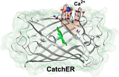
We previously designed a calcium sensor CatchER (a GFP-based Calcium sensor for detecting high concentrations in the high calcium concentration environment such as ER) with a capability for monitoring calcium ion responses in various types of cells. Calcium binding to CatchER induces the ratiometric changes in the absorption spectra, as well as an increase in fluorescence emission at 510 nm upon excitation at both 395 and 488 nm. Here, we have applied the combination of the steady-state and time-resolved optical methods and Hydrogen/Deuterium isotope exchange to understand the origin of such calcium-induced optical property changes of CatchER. We first demonstrated that calcium binding results in a 44% mean fluorescence lifetime increase of the indirectly excited anionic chromophore. Thus, CatchER is the first protein-based calcium indicator with the single fluorescent moiety to show the direct correlation between the lifetime and calcium binding. Calcium exhibits a strong inhibition on the excited-state proton transfer nonadiabatic geminate recombination in protic (vs deuteric) medium. Analysis of CatchER crystal structures and the MD simulations reveal the proton transfer mechanism in which the disrupted proton migration path in CatchER is rescued by calcium binding. Our finding provides important insights for a strategy to design calcium sensors and suggests that CatchER could be a useful probe for FLIM imaging of calcium in situ.
Introduction
Calcium transients are essential for intracellular calcium-dependent biological processes.1 The amplitude, duration, and kinetics of calcium concentration change embody the code to regulate downstream signaling. Such calcium signals are determined by the calcium gradients, the native calcium binding proteins, and the calcium channels as well as pumps. Calcium indicators with a wide range of calcium-binding affinities are needed to probe the spatial-temporal calcium dynamics in different subcellular compartments. The quantitative measurement is critical to understand [Ca2+] change and the resting calcium level in intracellular calcium stores and subcellular compartments.
For imaging calcium changes in biological systems, much effort has been taken to develop the fluorescent calcium biosensor toolkit.2−7 There is a broad range of choices for organic calcium dyes, including the ratiometric indicators, like the Fura and Indo series, and the single wavelength indicators, BAPTA, Fluo, and Rhod series.8 These organic dyes have a dissociation constant, Kd, range from 0.2 to 20 μM and are widely applied to monitor the intracellular calcium transients.
Genetically encoded calcium indicators (GECIs), based on fluorescent proteins, benefit the calcium concentration detection in specific cellular compartments, including GCaMP, Cameleon, Pericam, and the Troponin C (TN) series. These GECIs take advantage of the intrinsic calcium-binding properties of calmodulin or troponin C to induce the fluorescence intensity change upon calcium binding.4,9−13 These calcium indicators, with Kd in the magnitude from 10–7 to 10–6 M and slow calcium dissociation rates, are suitable to detect a calcium rise in cytosolic space but not for the calcium concentration change in the internal calcium stores such as the endoplasmic/sarcoplasmic reticulum (ER/SR). We have previously designed CatchER (Calcium sensor for detecting high concentration in the ER) as a sensitive fluorescence calcium probe with Kd of 0.18 mM.14 CatchER is created by the addition of a calcium binding site formed by five calcium ligand residues in the beta-barrel in proximity of the phenol group of the chromophore (Cro) from the single-enhanced green fluorescent protein (EGFP) carrying the deprotonated Cro (Figure 1).
Figure 1.
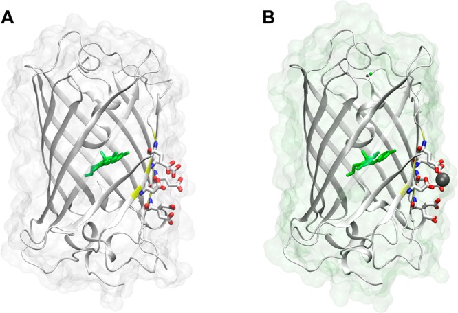
Crystal structure of (A) apo (PDB ID: 4L13) and (B) holo CatchER (PDB ID: 4L1I). The residues shown in stick form are the designed calcium binding site. Residues 164–168 are shown with 50% transparency. The residue shown in green is the chromophore. The atom shown in gray is the calcium atom. The oxygen atoms and nitrogen atoms are indicated in red and blue, respectively.
However, some major challenges for quantitative monitoring of the calcium cellular responses using the static fluorescence microscopy remain, including uneven dye loading, leakage, and photobleaching. The fluorescence lifetime imaging (FLIM) overcomes the limitations with its advantage of being independent of the concentration of fluorophore as well as the excitation light intensity.15,16 In FLIM, lifetime measurement takes place at each pixel, revealing the spatial distribution of the fluorescent molecules, allowing a simultaneous recording of multiple fluorescent labels with reliable discrimination.17 In addition, it is sensitive to the change of the microenvironment such as pH, the ion strength, hydrophobocity, oxygen concentration, and interaction with other macromolecules and protein–protein/protein–ligand interactions in situ.18−21 Thus, it provides insights into the local environment of the fluorophore. The in vivo lifetime imaging utility is being developed for small living animals to monitor the treatment of diseases, especially cancers.16,22−24 The lifetime imaging of calcium indicators, Quin-2, Calcium Green 1, and Oregon Green BAPTA (OGBs), have been used to monitor intracellular calcium transients.25−27 Here, we show CatchER is the first protein-based calcium indicator with the single fluorescent moiety to show the direct correlation between the lifetime and calcium binding, suggesting that CatchER could be a useful probe for FLIM imaging of calcium in cells.
CatchER belongs to the GFP protein family in which the prototropic properties in both the ground and the excited states are reasonably characterized.28−30 The general prototropic behavior of GFP-like Cro experiencing excited-state proton transfer (ESPT) is depicted by Scheme 1. The absorbance spectra of CatchER showed that the population of the neutral form (ROH) decreased while the anionic form (RO–) increased when calcium concentration increased. The fluorescence studies showed that the fluorescence intensity of the Ca2+-bound CatchER increased when CatchER was excited at both neutral (λabs 395 nm) and anionic (λabs 488 nm) forms. The dynamic properties of the excited CatchER, including its photophysical and photochemical properties, are still unknown. Indeed, the resulting apparent fluorescence lifetimes of both excited ROH (R*OH) and RO– (R*O–) are in direct connection with the steady-state fluorescence measurements commonly used in molecular biology.
Scheme 1. Simple Two-Level ESPT Kinetic Scheme.
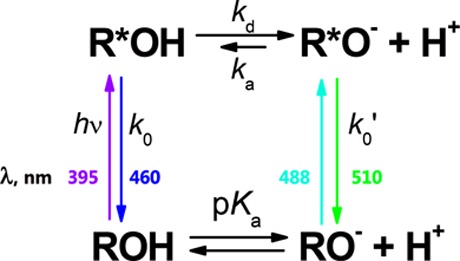
Here 1/k0 = τ0 and 1/k0′ = τ0′ are the fluorescence lifetimes of the excited protonated and deprotonated Cro, respectively. And kd and ka are the apparent rate constants of the excited-state dissociation and reprotonation, respectively.
In this paper, we conducted the time-resolved fluorescence measurements of CatchER to understand the calcium-induced fluorescence changes. The main goal of this study is to reveal the effects of Ca2+ on the ground and excited-state prototropic equilibrium in CatchER. Our results show that calcium binding alters the ionization state of CatchER Cro and reduces the nonadiabatic proton geminate recombination (quenching) in the excited state to increase the apparent lifetime of an indirectly excited anionic Cro. CatchER also exhibits the direct correlation between the lifetime and calcium binding. Our finding provides important insights into the strategy for designing calcium sensors and calcium-induced optical property changes.
Experimental Methods
Sample Preparation
CatchER was expressed by E. coli BL21 and purified using the Ni2+ charged prepacked Hi-Trap column and the size-exclusion column packed with Superdex-75 (GE Healthcare) using the established protocol.14 The concentrated pure proteins in 10 mM Tris, pH 7.4, were lyophilized and dissolved in H2O and D2O (95% D). The final pH and pD were checked and adjusted to 7.4 and 7.8, respectively. The pH cocktail buffer was prepared as 10 mM MES, 10 mM MOPS, 10 mM Tris, and 10 mM CAPS. The aliquots of 5 M KOH were titrated to increase the pH from 5.0.
To obtain the optimal signal in lifetime measurements, the absorbance spectra were collected and the protein concentration was adjusted to get the 395 nm peak maximum in the range of 0.2–0.3 OD. The final concentration of 10 mM Ca2+ was supplemented to obtain the calcium-loaded (holo) CatchER. The ground-state pKa of CatchER was calculated using eq 1,
| 1 |
where Y is the absorption of the neutral or anionic Cro at 395 or 488 nm, respectively; Yacid and Ybase are the absorption at the lowest and highest pH, respectively.
Lifetime Measurements
Fluorescence lifetimes were measured using an Edinburgh Instrument time-correlated single photon counting (TCSPC) system. In these measurements, picosecond excitation pulsed diode lasers (Picoquant) emitting at 372 or 467 nm were used as an excitation light source. The detection system consisted of a high-speed MicroChannel Plate PhotoMultiplier Tube (MCP-PMT, Hamamatsu R3809U-50) and TCSPC electronics. The time resolution of the system was 30 ps after deconvolution with an instrument response function (IRF) signal.
The QD fluorescence decays F(t) were fitted to multiexponential function after the convolution with the IRF:
| 2 |
The quality of fit was evaluated using the chi square and weighted residuals. To compare the time-resolved and the steady-state data, we used the amplitude-weighted average lifetimes of QD [τave =∑i = 1n(Aiτi/∑i = 1Ai)]. All measurements were carried out at 25 °C.
2.3. Molecular Dynamics Simulation
The 20 ns molecular dynamics (MD) simulation with an AMBER FF99SB force field was performed for both apo and calcium bound CatchER (PDB IDs: 4L13 and 4L1I)31 based on the particle mesh Ewald method. The atomic coordinates were taken from the crystal structures, and proteins were placed in a periodic box of TIP3P water by the AMBER tLEaP module. The system was first treated by 2500 steps of steep descent followed by 2500 steps of conjugate gradient minimization. After minimization, the system was heated to 300 K at 2 fs stepwise for 50 ps using the Langevin thermostat with the collision frequency of 1.0 ps–1. The weak restraint of 1.0 kcal mol–1 Å–1 was applied. Another 50 ps period was run without restraints to pre-equilibrate the system. Equilibrium runs were made for a 20 ns duration with a 2 fs time step. The temperature was controlled by the Langevin thermostat, and the pressure was maintained by isotropic position scaling with a relaxation time of 2 ps. All hydrogen atoms were constrained using the SHAKE algorithm. The space cut off was 9.0 Å, and the trajectory file was analyzed by the AMBER ptraj module. The hydrogen bond (H bond) cut off was set as 3.0 Å for donor–acceptor distance and 120° for a donor–hydrogen–acceptor angle.
Results and Discussion
pH Effect on the Ground and Excited-State Prototropic Behavior of CatchER
The pH titration of apo-CatchER (calcium-free) monitored by absorption spectroscopy is shown in Figure 2. At pH 5.0, a single peak with the maximum at 395 nm was observed, demonstrating the presence of only neutral Cro at these conditions. As the pH increased, the anionic Cro peak at 488 nm increased with the simultaneous decrease of the neutral absorption peak. At neutral pH, CatchER showed the presence of both the neutral and anionic forms of Cro in the ground (detected by absorption spectroscopy) and in the excited (detected by emission spectroscopy) states. At pH 9.3, the neutral-to-anionic peak ratio was 0.74. At a pH higher than 9.3, the peak of the anionic form began to decrease, and a shoulder around 465 nm was observed (not shown). At the same time, the peak maximum of the neutral Cro was red-shifted, and a shoulder was observed around 425 nm, indicating the degradation of protein at pH > 9.3. The pKa of CatchER Cro of 7.6 was determined using eq 1. Thus, the anionic form of the Cro was expected to be predominant at pH 10. However, the intensity of the neutral peak absorption was 60% of that at pH 5.0, implying that the portion of neutral Cro was solvent-inaccessible. Similar behavior is known for the wild-type GFP (wt-GFP) that shows very weak pH dependence of its absorption spectra in the pH range of 6–10.32,33 Alternatively, we propose that neutral Cro exists in two environments differing in the arrangement of the proton network around them. One such population can be easily titrated (we name it Cro1), while the other (Cro2) protects the Cro from the pH changes in the outside medium. From known extinction coefficients of the ROH and RO– in the GFP-type proteins and their synthetic Cros,34 we estimate the relative populations of Cro1 and Cro2 as very close. Such splitting of the ROH population for the number of GFP variants has already been reported.35,36
Figure 2.
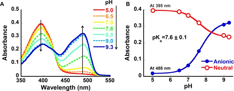
pH dependence of CatchER absorbance. (A) The pH titration from 5 to 9.3; (B) the pKa fitting by eq 2. The pH titration was carried out using 5 M KOH in a buffer cocktail consisting of 10 mM MES, 10 mM MOPS, and 10 mM CAPS, pH 5.0.
Figure 3 shows the emission spectra of CatchER at various pH levels. At pH 5.0, the excitation of CatchER led to a two-peak emission spectrum, the high-energy band at 465 nm belonging to the neutral Cro (R*OH), and the band at 510 nm from the anionic Cro (R*O–), formed via ESPT. With pH increase, the relative contribution of the 465 nm emission band decreased together with the relative population of the neutral Cro in the ground state (Figure 2). The emission maxima of the directly and indirectly excited anions (excited at 488 and 395 nm, respectively) are the same within the experimental error.
Figure 3.
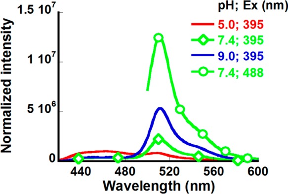
Emission spectra of CatchER in the cocktail buffer at different pH 5.0 (red), 7.4 (green ◇) and 9.0 (blue) when excited at 395 nm and the emission spectrum of CatchER at pH 7.4 when excited at 488 nm (green ○). The emission spectra were normalized by the absorbance at the corresponding excitation wavelength.
Fluorescence decay curves of R*OH and R*O– forms of CatchER at various pH are presented in Figure 4. The decay of R*OH at pH 9.6 belongs only to Cro2, which still exists in the neutral form at these conditions (Figure 2). The nonexponential decay of R*OH could be caused by the ESPT geminate recombination and nonhomogenous distribution of Cro conformers in the protein.37 Further analysis of the kinetic data is presented below.
Figure 4.
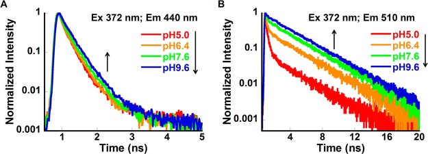
CatchER fluorescence decay at pH 5.0, 7.6, and 9.6. The excitation wavelength was 372 nm, and the emission wavelengths were (A) 440 nm and (B) 510 nm.
Ground and Excited-State Prototropic Behavior of CatchER
Fluorescence decay curves of R*OH and R*O– at pH 7.4 are shown in Figure 5. The decay of R*OH and the directly excited (at 467 nm) R*O– form could be fitted by the double-exponential expressions with the average lifetimes of 0.19 and 2.61 ns, respectively (Table 1). For the indirectly excited (at 372 nm) R*O– form, a fast quenching component within the first 2 ns was detected, which was followed by the long time asymptotic decay closely approaching the lifetime of the directly excited R*O– (Table 1). To make sure that our observation is not an experimental artifact, we have measured the fluorescence kinetics of the wt-GFP, and its several variants, and reproduced the published data. None of the known fluorescence proteins exhibited such fluorescence kinetic behavior of the indirectly excited R*O–, showing the characteristic biphasic decay.
Figure 5.
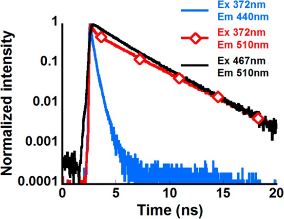
Fluorescence decay curves of CatchER at pH 7.4 excited and monitored at various wavelengths.
Table 1. Values of the Time Constants (τi) and Normalized (to 1) Pre-Exponential Factors (Ai) of the Multi-Exponential Function Fitting the ps-Emission Transients of CatchER in Various Solventsa.
| in H2O | τ1 (ns) | A1 | τ2 (ns) | A2 | τ3 (ns) | A3 | τave (ns) | |
|---|---|---|---|---|---|---|---|---|
| Ex372; Em440 | Apo | 0.15 ± 0.01 | 0.81 ± 0.01 | 0.37 ± 0.01 | 0.19 ± 0.01 | NA | NA | 0.19 ± 0.01 |
| Holo | 0.17 ± 0.01 | 0.81 ± 0.01 | 0.41 ± 0.01 | 0.19 ± 0.01 | NA | NA | 0.22 ± 0.01 | |
| Ex372; Em510 | Apo | 0.16 ± 0.03 | 0.47 ± 0.03 | 0.73 ± 0.24 | 0.09 ± 0.04 | 3.14 ± 0.03 | 0.44 ± 0.02 | 1.51 ± 0.10 |
| Holo | 0.21 ± 0.01 | 0.37 ± 0.02 | 3.34 ± 0.03 | 0.63 ± 0.02 | NA | NA | 2.18 ± 0.06 | |
| Ex467; Em510 | Apo | 2.01 ± 0.14 | 0.75 ± 0.11 | 4.47 ± 0.87 | 0.25 ± 0.11 | NA | NA | 2.61 ± 0.06 |
| Holo | 2.09 ± 0.03 | 0.77 ± 0.01 | 4.73 ± 0.10 | 0.23 ± 0.01 | NA | NA | 2.54 ± 0.19 | |
| in D2O | τ1 (ns) | A1 | τ2 (ns) | A2 | τ3 (ns) | A3 | τave (ns) | |
|---|---|---|---|---|---|---|---|---|
| Ex372; Em440 | Apo | 0.12 ± 0.01 | 0.79 ± 0.08 | 0.31 ± 0.06 | 0.21 ± 0.06 | NA | NA | 0.16 ± 0.01 |
| Holo | 0.14 ± 0.01 | 0.87 ± 0.01 | 0.40 ± 0.01 | 0.13 ± 0.01 | NA | NA | 0.17 ± 0.01 | |
| Ex372; Em510 | Apo | 0.10 ± 0.02 | 0.67 ± 0.07 | 0.39 ± 0.10 | 0.17 ± 0.07 | 3.06 ± 0.04 | 0.15 ± 0.01 | 0.61 ± 0.03 |
| Holo | 0.13 ± 0.01 | 0.60 ± 0.04 | 0.41 ± 0.10 | 0.15 ± 0.05 | 3.42 ± 0.01 | 0.25 ± 0.01 | 0.99 ± 0.05 | |
| Ex467; Em510 | Apo | 2.18 ± 0.24 | 0.81 ± 0.01 | 5.24 ± 0.10 | 0.19 ± 0.02 | NA | NA | 2.55 ± 0.16 |
| Holo | 1.81 ± 0.03 | 0.56 ± 0.16 | 3.62 ± 0.46 | 0.44 ± 0.16 | NA | NA | 2.60 ± 0.07 | |
The amplitude-weighted average lifetimes of τave were calculated as [τave = ∑i = 1n(Aiτi/∑i = 1Ai)].
Upon calcium addition, the fluorescence decay of the directly excited R*OH and R*O– did not differ significantly (Figure 6). These results are in agreement with the previous observation that the quantum yield of CatchER was not affected by calcium when excited at 488 nm.14
Figure 6.

Fluorescence decay traces of Ca2+-free CatchER (Apo, open symbol, dash line) and CatchER supplemented with 10 mM Ca2+ (Holo, closed symbol, solid line) in H2O (red) and D2O (gray). Protein samples were prepared in 10 mM Tris, pH 7.4.
Meanwhile, the amplitude of the initial fast decay component observed in the indirectly excited R*O– was dramatically reduced, and the lifetime for the long-time asymptotic decay increased in the presence of calcium (Figure 6). The average lifetime of the indirectly excited anionic form was increased by 44% from 1.51 to 2.18 ns when calcium was bound to CatchER.
At pH 7.4, both the neutral and anionic Cros were present in the absorption spectra, with the peak height ratio ARO−/AROH of 0.43 (as shown in Figure 7). The anionic emission maxima was observed at 510 nm when excited at either 395 or 488 nm, and the intensity of the indirectly excited R*O– was 45% of the directly excited species. With the addition of calcium, the population of the neutral and the anionic Cro was changed, leading to the ratio ARO−/AROH increase to 0.58. The steady-state fluorescence spectra showed that the R*O– intensity was increased by 50% and 30% upon calcium binding when excited at 395 and 488 nm, respectively.
Figure 7.
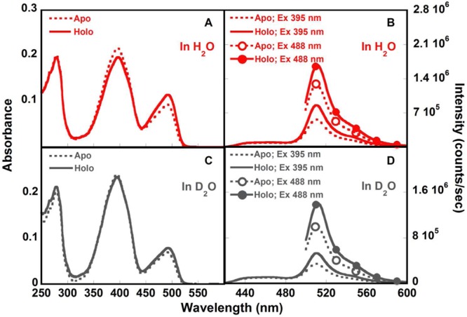
Absorption and fluorescence spectra of CatchER in H2O (red, A and B) and D2O (gray, C and D), in the absence (Apo, dash line) and presence of 10 mM Ca2+ (Holo, solid line). Protein samples were prepared in 10 mM Tris, pH 7.4.
At the same time, in the normalized emission spectra (Figure 8), the peak height ratio IR*OH/IR*O− was higher for apo- than for the holo-CatchER. It is known that IR*OH/IR*O− ∼ 1/(kdτ′), where kd is the proton dissociation rate during ESPT and τ′ is average lifetime of the indirectly excited R*O–.38 The higher ratio IR*OH/IR*O− in apo-CatchER than holo-CatchER indicated the larger population of R*O– remained in the excited state with the additional calcium. Therefore, the calcium binding shifts the acid–base equilibrium of the CatchER Cro in the ground state toward the anion. On the other hand, the calcium binding reduces the fast deactivation component in the decay of R*O–.
Figure 8.
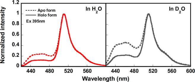
Normalized fluorescence emission spectra (λex 395 nm) of Ca2+-free CatchER (Apo, dash line) and CatchER in the presence of 10 mM Ca2+ (Holo, solid line) in H2O (red) and D2O (gray).
Kinetic Isotope Effect
The fluorescence decay of apo- and holo-CatchER was measured in H2O and D2O-based buffers to obtain the H/D kinetic isotope effect (KIE). The latter may reveal the rate-limiting steps in the photoinduced proton-transfer cascade. No kinetic H/D isotope effect was found in the fluorescence decay of the directly excited neutral and anionic forms at room temperature, meaning that rates of proton dissociation as well as the decay of the R*OH and R*O– are nonsensitive to H/D exchange. However, a substantial H/D isotopic effect was observed for the indirectly excited R*O– (Figure 6), for which the average lifetime was 1.5 ns in H2O and 610 ps in D2O. Interestingly, the amplitude of the short-time quenching component was larger in D2O than in H2O (Table 1). Altogether, the H/D KIE and the Ca2+ effects on the nonadiabatic geminate recombination were similar.
Analysis of CatchER Hydrogen-Bond Network by Molecular Dynamics Simulation
To provide the structural basis for the observed spectral and prototropic behavior of CatchER, we have performed the MD simulation in the static state using our recently determined X-ray structures of calcium free (PDB ID: 4L13) and calcium loaded (PDB ID: 4L1I) CatchER.31 Table 2 shows the probability of hydrogen bonds (H bonds) formed in the Cro environment, including Cro, H148, T203, S205, E222, and bridging water molecules labeled as in Figure 9. In holo-CatchER, the hydrogen-bond network extends from the Cro tyrosyl (Cro–OH), WAT1, S205-OG, and finally to E222-OE2. The Cro tyrosyl served as an H-bond donor to the bridging water molecule WAT1 connecting S205 with an occupancy of 92%. The probability to form the H bond between the S205 side chain (S205-OG) and WAT1 was 6.5%, while the formation between S205 and E222 was 98.5%. In contrast, WAT1 was the H bond donor for the Cro tyrosyl with the occurrence of 15.5% in apo-CatchER, and the H-bond between the S205 hydroxyl and the bridging water (WAT1) was missing. Instead, the Cro tyrosyl served as the H-bond donor for the H148-ND1 with occupancy of 41.5%.
Table 2. Hydrogen Bond Analysis in the Cro Environment by MD Simulation.
| occupancy |
|||
|---|---|---|---|
| donora | acceptora | apo | holo |
| CRO-OG1 | E222-OE2 | 88.5 | 91.5 |
| WAT1 | CRO-OH | 15.5 | N/A |
| CRO-OH | WAT1 | N/A | 92.0 |
| CRO-OH | H148-ND1 | 41.5 | N/A |
| WAT1 | S205-OG | N/A | 6.5 |
| S205-OG | E222-OE2 | 85 | 98.5 |
| H148–N | T203-O | 44.5 | 54.5 |
| WAT2 | E222-OE1 | 16.5 | NA |
| WAT2 | T203-OG1 | 10.5 | 31 |
| WAT3 | E222-OE1 | 43 | 40 |
| WAT2 | WAT3 | 24.5 | 35.5 |
| Q69-NE2 | WAT2 | 40.5 | 68.5 |
The residue and atoms names of H-bond donors and acceptors were given based on the pdb files.
Figure 9.
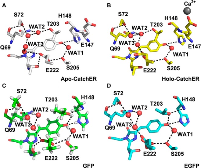
Comparison of the crystal structures of (A) apo-CatchER (PDB ID: 4L13), (B) Ca2+-CatchER (PDB ID: 4L1I), (C) GFP (PDB ID: 2WUR), and (D) EGFP (PDB ID: 4EUL). The H bonds are shown in the black dash line with the cutoff of 3.5 Å. Only side chains were shown in S72, T203, S205, and E222.
On the other side from the side chain of Q69, a proton can migrate to E222. Here, water molecules WAT2 and WAT3 connect the side chains of E222, Q69, and T203. In both apo and Ca2+-loaded CatchER, the water molecule WAT2 serves as the proton donor for both T203 side chain and WAT3. Although the probability of WAT2-WAT3-E222 was higher in Ca2+-CatchER, it was found that WAT2 can directly form the H bond to the E222 side chain with occupancy of 16.5%. Ca2+ effect on the proton wire to E222 is not significant based on the 20 ns MD simulation.
Structural Effects in CatchER on the Ground State Spectra
The unique optical properties of GFP has attracted extensive research interest for decades.39 In 1996, Chattoraj and co-workers first proposed there were different forms (the protonated neutral Cro as A form, an intermediate I form, and the deprotonated anionic Cro as B form) in GFP, which can convert to each other by proton migration.40 In the same year, the crystal structures of wt-GFP and its S65T mutant, known as EGFP, were published.41,42 The spectral property was altered due to the mutation S65T in EGFP, where the anionic deprotonated Cro with the absorption maximum wavelength at 488 nm dominates, while wt-GFP has a larger population of neutral protonated Cro at pH 7.0. With five mutations on the β-barrel surface of EGFP, the spectral property of CatchER is closer to wt-GFP than EGFP, where the protonated neutral Cro is dominated at pH 7.0.
The crystal structure of CatchER, recently determined by us,31 demonstrates that the side chain of T203 is in the opposite position of what it shows in both GFP and EGFP (as shown in Figure 9). Fewer H-bond donors around the CatchER Cro, compared to wt-GFP43 and EGFP,44 lead to the tyrosyl group being prone to be protonated, which is also observed in cpEGFP 149–144.11,45 The pH profile of apo- and holo-CatchER absorption spectra suggests that the pKa of holo-CatchER is a little lower than the apo form, implying that the Cro is more deprotonated upon calcium binding.14 Since calcium binding does not alter the conformation of T203, perhaps such acid–base equilibrium shifts originated from other residues in the Cro H-bond network. It is observed that the distance between H148-ND1 and the tyrosyl of Cro is 3.3 and 3.2 Å, a reasonable range for a H-bond formation in both apo and holo forms of CatchER, respectively. Upon calcium binding, the electrostatic neutralization of one ligand, E147, results in the redistribution of electron density through bonds by inductive effect, which in turn may increase the pKa of the H148 side chain. Thus, the protonated side chain of H148 can help to stabilize the deprotonated Cro tyrosyl. This assumption is in agreement with the MD simulation results that the deprotonated H148-ND1 is the H-bond acceptor in the pair (Cro-tyrosyl)-(H148-ND1) in apo-CatchER but not in the holo form.
Calcium Effect on CatchER Fluorescence Lifetimes and ESPT
Previously, we have discovered that the optical properties of CatchER resemble those of several GFP mutants. Excitation of both the neutral and the anion forms resulted in an emission band with a maximum at 510 nm (Figure 3). Therefore, the simplest kinetic scheme describing the prototropic behavior of CatchER may be first depicted by Scheme 1 that is different from the wt-GFP with intermediate anionic states.40
The ground-state population of CatchER is represented by Cro1 and Cro2, differing in their pH-susceptibility and not existing in the dynamic equilibrium (otherwise both populations would be deprotonated at pH 9.3). These Cros are spectrally indistinguishable in both absorption and emission spectra, therefore, the observed ROH, RO–, R*OH, and R*O– spectral bands are the superposition of Cro1 and Cro2 spectra. The excited-state R*OH decay lifetimes of pure Cro2 at pH 9.6 and the 1/1 Cro1–Cro2 mixture at pH 5.0 (Figure 4A) do not differ by more than a factor of 2, demonstrating similar ESPT dissociation reactivity for both forms. Although the Cro1 and Cro2 cannot be differentiated in both apo-CatchER crystal structure,31 the side chain of E222 in Ca2+-CatchER shows a double conformer in a 1:1 occupancy, probably responsible for Cro1 and Cro2 populations.
The kinetic Scheme 1, however, does not explain the deviation from mono- and biexponential fluorescence decays of R*OH and R*O– often observed experimentally for strong photoacids.46,47 To explain this phenomenon, Agmon and co-workers48−51 expanded Scheme 1 into two reaction steps (Scheme 2). The photoinduced protolytic dissociation of R*OH, with an intrinsic rate constant kd, leads to formation of the contact ion pair (CIP) R*O–···H+, whereas adiabatic recombination, with rate constant kr, may reform the excited acid. Additionally, back protonation may proceed also by a nonadiabatic pathway, involving proton quenching (nonadiabatic geminate recombination) with a rate constant kq. Separation of a CIP from the contact radius to infinity is described by the transient numerical solution of the Debye–Smoluchowski equation (DSE). As in Scheme 1, all excited species decay to the ground state, but the decay rate k0″ for the CIP is usually much slower than all chemical and diffusion processes and can be ignored. Since no analytical solution exists for the system of coupled DSEs describing the time evolution of R*OH and R*O–, the solution can be obtained numerically by the publically available SSDP package.52 One of the characteristic features of the R*O– decay in the presence of proton quenching is the unique biphasic decay of this transient observed in a number of “super” photoacids. It is important to stress, that for complicated proteinous systems such as CatchER, several input parameters required by the SSDP include a number of variables almost impossible to estimate realistically (diffusion coefficient of proton, the radius of reaction sphere, outer boundary conditions, the profile of the electrostatic potential inside the protein, etc.). Therefore, we will not attempt to fit the full profile of the R*OH and R*O– fluorescence decay curves in CatchER. Instead, we will analyze the overall characteristic decay profiles of these species, especially the indirectly excited R*O–. As mentioned earlier, the characteristic shape of its decay is a fingerprint of the nonadiabatic proton geminate recombination. Therefore, our work is the first observation of this unique kinetic behavior in fluorescent proteins.
Scheme 2. Two-Step Diffusion-Influenced ESPT Kinetic Scheme.
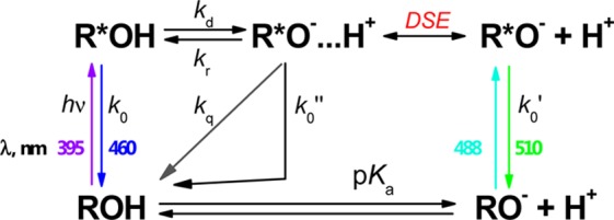
The ESPT dissociation rate, kd, as well as both k0 and k0′ were calcium-independent. The average fluorescence lifetime of the directly excited anionic Cro was consistent with the reported lifetime of EGFP (2.54 ns)53 in an acceptable error range. However, the nonadiabatic geminate recombination rate, kq, was inhibited by Ca2+, as can be judged by the magnitude of the fast-decaying component in R*O–, since for kq = 0, the R*O– would decay monoexponentially. As a result, a larger population of R*O– remained in the excited state, resulting in a higher ratio IR*O- /IR*OH, which was in agreement with the observation shown in Figure 8. Calcium binding also leads to the increase of the long-time asymptotic decay, τ0′, when the anionic form R*O– was indirectly excited.
In 1997 and 2000, Palm and Remington reported the crystal structures of several mutants and summarized the spectral relevance to the three forms (A, B, and I).54,55 The ESPT pathway was first revealed as the tyrosyl of the Cro, the bridging water molecule (WAT1), S205 and E222. Agmon and co-workers extended the view of the proton conduction in the protein matrix along 1D proton wires and described the proton pathways, including the proton exiting the β-barrel by rotation of T203 and the slow re-entry (μs) from the opposite side of GFP.56−58 In this theory, T203 hydroxyl in the anionic B-state of GFP accepts the proton of Cro–OH and donates the H-bond to the main chain of H148, so-called the “out state” of T203, which is observed in the Ca2+-GCaMP2 (PDB ID: 3EVR) and EGFP (PDB ID: 4EUL),44,45 as well as in the wt-GFP crystal structure of higher resolution (PDB ID: 2WUR). In the acid A-state of GFP, T203 adopts the “in” conformer, in which the side chain of T203 rotates 120° from the “out” state and T203-OH is not able to form the H bond to Cro–OH. The wt-GFP (PDB ID: 1GFL) and circular permutated EGFP (PDB ID: 3EVP) show the conformation of T203 as the “in” state.
As shown in Figure 9, we observed only the “in” state of the T203 side chain in both apo- and Ca2+-CatchER crystal structures. On the basis of the MD simulation, the water molecule WAT2 serves as the H-bond donor for both T203 hydroxyl and indirectly for E222 via the other water molecules. The H bond between Q69-WAT2-T203 can stabilize the side-chain position and make the rotation less possible. The absence of the “threonine switch”, proposed by Agmon,56 would prevent the proton from escaping the beta-barrel and increase its probability to recombine with the parent R*O– during ESPT.
In the 20 ns MD simulation, it was observed that the proton wire, consisting of the Cro tyrosyl, the bridging water (WAT1), S205, and E222, was disrupted by the introduction of the negatively charged Ca2+ binding site, which was known to be pivotal for ESPT. Ca2+ binding rescued this proton transfer pathway. Such a disturbed proton wire (Cro-WAT1-S205-E222) in apo-CatchER can explain the larger contribution of the nonadiabatic geminate recombination phenomenon due to the lack of an efficient proton migration path.
The broken proton migration pathway also explains the inverse H/D kinetic isotope effect. It is known that the diffusion constant of the deuterium ion is 1.4-fold smaller than that of the proton.59,60 The deuteron could be restricted in the Cro environment, facilitating the reprotonation of the latter. We hypothesize that in H2O, the probability of the proton to escape from the Cro vicinity is higher, causing less geminate recombination. Therefore, in the static fluorescence spectra, the higher ratio IR*OH/IR*O– of CatchER in D2O (Figure 8) does not mean slower proton dissociation, which leads to an H/D KIE of about 5 in wt-GFP for the lifetime of the indirectly excited R*O–.40 On the contrary, the slow diffusion of deuterium makes it easier to reprotonate the deprotonated excited Cro (both adiabatically and nonadiabatically), especially in the situation where the deuterium has little chance to travel to the H-bond acceptor, leading to the shorter average lifetime of indirectly excited R*O–. As a result, larger geminate proton quenching of R*O– was observed in D2O, which resulted in the decreased average fluorescent lifetime.
Conclusions
In summary, binding of Ca2+ to CatchER results in the increase of the dominating green emission from this protein. Such fluorescence increase is caused by the combination of thermodynamic (change of the ground-state acid–base equilibrium) and kinetic factors. The latter is mostly based on the unusual dependence of the nonadiabatic proton geminate recombination on Ca2+ binding and H/D isotope exchange. The longer average lifetime of indirectly excited anionic Cro (caused by retarded proton geminate recombination) measured in the presence of calcium versus the apo-CatchER is proposed to arise from the different arrangement of the proton wire with and without calcium binding.
Our results demonstrate that CatchER is the first example of proton nonadiabatic geminate recombination in fluorescent proteins. Such unusual utilization of this photoinduced process in metalloproteomics opens new horizons in this rapidly expanding area. Our finding here reveals a new strategy to tune the fluorescence properties of the metalloproteins by metal binding that alters the intraprotein photoinduced proton transfer. CatchER is also the first GECI of the single wavelength calcium detection that has the feature of calcium-dependent lifetime change. The results about the calcium-induced lifetime changes of R-CaMP are yet to be reported.61 For the FRET pair based calcium indicator TN-XXL, the donor lifetime decrease was observed upon calcium binding. However, the small dynamic range of the donor lifetime change (10–20%) and the complexity of the multiexponential decay were not optimal for the FLIM.62,63 Hence, such an increase (>40%) of the average lifetime (caused by the change of the amplitude ratio for two decaying components) of indirect excitation of R*O– enables CatchER to quantitatively monitor calcium dynamics by lifetime imaging in the future.
Acknowledgments
We thank Noam Agmon, Irene Weber, and Ying Zhang for helpful discussions. We also thank Jingjuan Qiao, Cassie Miller, and Kathy Meenach for their critical review and assistance. This work is supported, in part, by NIH Grants GM081749 and EB007268 and a Brain & Behavior (BB) seed grant to J.J.Y.; a BB fellowship to Y.Z., and K.M.S. acknowledges generous support from the National Science Foundation (CHE-1213047).
The authors declare no competing financial interest.
Funding Statement
National Institutes of Health, United States
References
- Clapham D. E. Calcium signaling. Cell 2007, 131, 1047–1058. [DOI] [PubMed] [Google Scholar]
- Rizzuto R.; Simpson A. W.; Brini M.; Pozzan T. Rapid changes of mitochondrial Ca2+ revealed by specifically targeted recombinant aequorin. Nature 1992, 358, 325–327. [DOI] [PubMed] [Google Scholar]
- Grynkiewicz G.; Poenie M.; Tsien R. Y. A new generation of Ca2+ indicators with greatly improved fluorescence properties. J. Biol. Chem. 1985, 260, 3440–3450. [PubMed] [Google Scholar]
- Miyawaki A.; Llopis J.; Heim R.; McCaffery J. M.; Adams J. A.; Ikura M.; Tsien R. Y. Fluorescent indicators for Ca2+ based on green fluorescent proteins and calmodulin. Nature 1997, 388, 882–887. [DOI] [PubMed] [Google Scholar]
- Griesbeck O.; Baird G. S.; Campbell R. E.; Zacharias D. A.; Tsien R. Y. Reducing the environmental sensitivity of yellow fluorescent protein. Mechanism and applications. J. Biol. Chem. 2001, 276, 29188–29194. [DOI] [PubMed] [Google Scholar]
- Chen T. W.; Wardill T. J.; Sun Y.; Pulver S. R.; Renninger S. L.; Baohan A.; Schreiter E. R.; Kerr R. A.; Orger M. B.; Jayaraman V.; et al. Ultrasensitive fluorescent proteins for imaging neuronal activity. Nature 2013, 499, 295–300. [DOI] [PMC free article] [PubMed] [Google Scholar]
- Zhao Y.; Araki S.; Wu J.; Teramoto T.; Chang Y. F.; Nakano M.; Abdelfattah A. S.; Fujiwara M.; Ishihara T.; Nagai T.; et al. An expanded palette of genetically encoded Ca(2) indicators. Science 2011, 333, 1888–1891. [DOI] [PMC free article] [PubMed] [Google Scholar]
- Paredes R. M.; Etzler J. C.; Watts L. T.; Zheng W.; Lechleiter J. D. Chemical calcium indicators. Methods 2008, 46, 143–151. [DOI] [PMC free article] [PubMed] [Google Scholar]
- Heim N.; Griesbeck O. Genetically encoded indicators of cellular calcium dynamics based on troponin C and green fluorescent protein. J. Biol. Chem. 2004, 279, 14280–14286. [DOI] [PubMed] [Google Scholar]
- Whitaker M. Genetically encoded probes for measurement of intracellular calcium. Methods Cell Biol. 2010, 99, 153–182. [DOI] [PMC free article] [PubMed] [Google Scholar]
- Nakai J.; Ohkura M.; Imoto K. A high signal-to-noise Ca(2+) probe composed of a single green fluorescent protein. Nat. Biotechnol. 2001, 19, 137–141. [DOI] [PubMed] [Google Scholar]
- Nagai T.; Yamada S.; Tominaga T.; Ichikawa M.; Miyawaki A. Expanded dynamic range of fluorescent indicators for Ca(2+) by circularly permuted yellow fluorescent proteins. Proc. Natl. Acad. Sci. U.S.A. 2004, 101, 10554–10559. [DOI] [PMC free article] [PubMed] [Google Scholar]
- Griesbeck O.; Baird G. S.; Campbell R. E.; Zacharias D. A.; Tsien R. Y. Reducing the environmental sensitivity of yellow fluorescent protein: Mechanism and applications. J. Biol. Chem. 2001, 276, 29188–29194. [DOI] [PubMed] [Google Scholar]
- Tang S.; Wong H. C.; Wang Z. M.; Huang Y.; Zou J.; Zhuo Y.; Pennati A.; Gadda G.; Delbono O.; Yang J. J. Design and application of a class of sensors to monitor Ca2+ dynamics in high Ca2+ concentration cellular compartments. Proc. Natl. Acad. Sci. U.S.A. 2011, 108, 16265–16270. [DOI] [PMC free article] [PubMed] [Google Scholar]
- Lakowicz J. R.; Geddes C. D.. Topics in Fluorescence Spectroscopy: Lifetime-Based Sensing; Plenum Press: New York, 1991. [Google Scholar]
- Lakowicz J. R.; Szmacinski H.; Nowaczyk K.; Berndt K. W.; Johnson M. Fluorescence lifetime imaging. Anal. Biochem. 1992, 202, 316–330. [DOI] [PMC free article] [PubMed] [Google Scholar]
- Kumar A. T. N.; Raymond S. B.; Bacskai B. J.; Boas D. A. Comparison of frequency-domain and time-domain fluorescence lifetime tomography. Opt. Lett. 2008, 33, 470–472. [DOI] [PMC free article] [PubMed] [Google Scholar]
- Gannot I.; Ron I.; Hekmat F.; Chernomordik V.; Gandjbakhche A. Functional optical detection based on pH dependent fluorescence lifetime. Lasers Surg. Med. 2004, 35, 342–348. [DOI] [PubMed] [Google Scholar]
- Harvey C. D.; Yasuda R.; Zhong H.; Svoboda K. The spread of Ras activity triggered by activation of a single dendritic spine. Science 2008, 321, 136–140. [DOI] [PMC free article] [PubMed] [Google Scholar]
- Yasuda R.; Harvey C. D.; Zhong H.; Sobczyk A.; van Aelst L.; Svoboda K. Supersensitive Ras activation in dendrites and spines revealed by two-photon fluorescence lifetime imaging. Nat. Neurosci. 2006, 9, 283–291. [DOI] [PubMed] [Google Scholar]
- Huang P. C.; Chiu T. Y.; Wang L. C.; Teng H. C.; Kao F. J.; Yang D. M. Visualization of the Orai1 homodimer and the functional coupling of Orai1-STIM1 by live-cell fluorescence lifetime imaging. Microsc. Microanal. 2010, 16, 313–326. [DOI] [PubMed] [Google Scholar]
- Bloch S.; Lesage F.; McIntosh L.; Gandjbakhche A.; Liang K.; Achilefu S. Whole-body fluorescence lifetime imaging of a tumor-targeted near-infrared molecular probe in mice. J. Biomed. Opt. 2005, 10, 054003. [DOI] [PubMed] [Google Scholar]
- Godavarty A.; Sevick-Muraca E. M.; Eppstein M. J. Three-dimensional fluorescence lifetime tomography. Med. Phys. 2005, 32, 992–1000. [DOI] [PubMed] [Google Scholar]
- Ardeshirpour Y.; Chernomordik V.; Zielinski R.; Capala J.; Griffiths G.; Vasalatiy O.; Smirnov A. V.; Knutson J. R.; Lyakhov I.; Achilefu S.; et al. In vivo fluorescence lifetime imaging monitors binding of specific probes to cancer biomarkers. PLoS One 2012, 7, e31881. [DOI] [PMC free article] [PubMed] [Google Scholar]
- Lakowicz J. R.; Szmacinski H.; Nowaczyk K.; Johnson M. L. Fluorescence lifetime imaging of calcium using Quin-2. Cell Calcium 1992, 13, 131–147. [DOI] [PMC free article] [PubMed] [Google Scholar]
- Lakowicz J. R.; Szmacinski H.; Nowaczyk K.; Lederer W. J.; Kirby M. S.; Johnson M. L. Fluorescence lifetime imaging of intracellular calcium in COS cells using Quin-2. Cell Calcium 1994, 15, 7–27. [DOI] [PMC free article] [PubMed] [Google Scholar]
- Agronskaia A. V.; Tertoolen L.; Gerritsen H. C. Fast fluorescence lifetime imaging of calcium in living cells. J. Biomed. Opt. 2004, 9, 1230–1237. [DOI] [PubMed] [Google Scholar]
- Meech S. R.Primary Photophysical Processes in Chromoproteins. In Fluorescent Proteins I; Jung G., Ed.; Springer: New York, 2012. [Google Scholar]
- Chirico G.; Collini M.; D’Alfonso L.; Caccia M.; Daglio S. C.; Campanini B.. Green Fluorescent Protein Photodynamics As a Tool for Fluorescence Correlative Studies and Applications. In Fluorescent Proteins II, Jung G., Ed.; Springer: New York, 2012. [Google Scholar]
- Helms V.; Gu W.. Proton Travel in Green Fluorescent Protein. In Fluorescent Proteins I; Jung G., Ed.; Springer: New York, 2012. [Google Scholar]
- Zhang Y.; Reddish F.; Tang S.; Zhuo Y.; Wang Y.; Yang J. J.; Weber I. T. Structural basis for a hand-like site of the calcium sensor CatchER with fast kinetics. Acta Crystallogr., Sect. D: Biol. Crystallogr. 2013, 69, 2309–2319. [DOI] [PMC free article] [PubMed] [Google Scholar]
- Ward W. W.Properties of the Coelenterate Green Fluorescent Proteins. In Bioluminescence and Chemiluminescence: Basic Chemistry and Analytical Applications; DeLuca M. A.; McElroy W. D., Eds.; Academic Press: New York, 1981; pp 225–234. [Google Scholar]
- Campbell T. N.; Choy F. Y. M. The Effect of pH on Green Fluorescent Protein: A Brief Review. Mol. Biol. Today 2001, 2, 1–4. [Google Scholar]
- Dong J.; Solntsev K. M.; Tolbert L. M. Solvatochromism of the green fluorescence protein chromophore and its derivatives. J. Am. Chem. Soc. 2006, 128, 12038–12039. [DOI] [PubMed] [Google Scholar]
- Leiderman P.; Genosar L.; Huppert D.; Shu X.; Remington S. J.; Solntsev K. M.; Tolbert L. M. Ultrafast excited-state dynamics in the green fluorescent protein variant S65T/H148D. 3. Short- and long-time dynamics of the excited-state proton transfer. Biochemistry 2007, 46, 12026–12036. [DOI] [PubMed] [Google Scholar]
- Fron E.; Van der Auweraer M.; Moeyaert B.; Michiels J.; Mizuno H.; Hofkens J.; Adam V. Revealing the excited-state dynamics of the fluorescent protein Dendra2. J. Phys. Chem. B 2013, 117, 2300–2313. [DOI] [PubMed] [Google Scholar]
- Gepshtein R.; Leiderman P.; Huppert D. Origin of the nonexponential dynamics of excited-state proton transfer in wt-green fluorescent protein. J. Phys. Chem. B 2008, 112, 7203–7210. [DOI] [PubMed] [Google Scholar]
- Solntsev K. M.; Al-Ainain S. A.; Il’ichev Y. V.; Kuzmin M. G. Effects of long-chain alkyl substituents on the protolytic reactions of naphthols. J. Photochem. Photobiol., A: Chemistry 2005, 175, 178–191. [Google Scholar]
- Dedecker P.; De Schryver F. C.; Hofkens J. Fluorescent proteins: Shine on, you crazy diamond. J. Am. Chem. Soc. 2013, 135, 2387–2402. [DOI] [PubMed] [Google Scholar]
- Chattoraj M.; King B. A.; Bublitz G. U.; Boxer S. G. Ultra-fast excited state dynamics in green fluorescent protein: Multiple states and proton transfer. Proc. Natl. Acad. Sci. U.S.A. 1996, 93, 8362–8367. [DOI] [PMC free article] [PubMed] [Google Scholar]
- Yang F.; Moss L. G.; Phillips G. N. Jr. The molecular structure of green fluorescent protein. Nat. Biotechnol. 1996, 14, 1246–1251. [DOI] [PubMed] [Google Scholar]
- Ormo M.; Cubitt A. B.; Kallio K.; Gross L. A.; Tsien R. Y.; Remington S. J. Crystal structure of the Aequorea victoria green fluorescent protein. Science 1996, 273, 1392–1395. [DOI] [PubMed] [Google Scholar]
- Shinobu A.; Palm G. J.; Schierbeek A. J.; Agmon N. Visualizing proton antenna in a high-resolution green fluorescent protein structure. J. Am. Chem. Soc. 2010, 132, 11093–11102. [DOI] [PubMed] [Google Scholar]
- Arpino J. A.; Rizkallah P. J.; Jones D. D. Crystal structure of enhanced green fluorescent protein to 1.35 A resolution reveals alternative conformations for Glu222. PLoS One 2012, 7, e47132. [DOI] [PMC free article] [PubMed] [Google Scholar]
- Wang Q.; Shui B.; Kotlikoff M. I.; Sondermann H. Structural basis for calcium sensing by GCaMP2. Structure 2008, 16, 1817–1827. [DOI] [PMC free article] [PubMed] [Google Scholar]
- Solntsev K. M.; Agmon N. Dual asymptotic behavior in geminate diffusion-influenced reaction. Chem. Phys. Lett. 2000, 320, 262–268. [Google Scholar]
- Solntsev K. M.; Sullivan E. N.; Tolbert L. M.; Ashkenazi S.; Leiderman P.; Huppert D. Excited-state proton transfer reactions of 10-hydroxycamptothecin. J. Am. Chem. Soc. 2004, 126, 12701–12708. [DOI] [PubMed] [Google Scholar]
- Pines E.; Huppert D.; Agmon N. Geminate recombination in excited-state proton-transfer reactions: Numerical solution of the Debye–Smoluchowski equation with backreaction and comparison with experimental results. J. Chem. Phys. 1988, 88, 5620–5630. [Google Scholar]
- Agmon N.; Pines E.; Huppert D. Geminate recombination in proton-transfer reactions. II. Comparison of diffusional and kinetic schemes. J. Chem. Phys. 1988, 88, 5631–5638. [Google Scholar]
- Gopich I. V.; Solntsev K. M.; Agmon N. Excited-state reversible geminate reaction. I. Two different lifetimes. J. Chem. Phys. 1999, 110, 2164–2174. [Google Scholar]
- Agmon N. Excited-state reversible geminate reaction. II. Contact geminate quenching. J. Chem. Phys. 1999, 110, 2175–2180. [Google Scholar]
- Krissinel E. B.; Agmon N. Spherical symmetric diffusion problem. J. Comput. Chem. 1996, 17, 1085–1098. [Google Scholar]
- van Thor J. J. Photoreactions and dynamics of the green fluorescent protein. Chem. Soc. Rev. 2009, 38, 2935–2950. [DOI] [PubMed] [Google Scholar]
- Palm G. J.; Zdanov A.; Gaitanaris G. A.; Stauber R.; Pavlakis G. N.; Wlodawer A. The structural basis for spectral variations in green fluorescent protein. Nat. Struct. Biol. 1997, 4, 361–365. [DOI] [PubMed] [Google Scholar]
- Remington S. J. Structural basis for understanding spectral variations in green fluorescent protein. Methods Enzymol. 2000, 305, 196–211. [DOI] [PubMed] [Google Scholar]
- Agmon N. Proton pathways in green fluorescence protein. Biophys. J. 2005, 88, 2452–2461. [DOI] [PMC free article] [PubMed] [Google Scholar]
- Leiderman P.; Huppert D.; Agmon N. Transition in the temperature-dependence of GFP fluorescence: From proton wires to proton exit. Biophys. J. 2006, 90, 1009–1018. [DOI] [PMC free article] [PubMed] [Google Scholar]
- Agmon N. Kinetics of switchable proton escape from a proton-wire within green fluorescence protein. J. Phys. Chem. B 2007, 111, 7870–7878. [DOI] [PubMed] [Google Scholar]
- Roberts N. K.; Northey H. L. Proton and deuteron mobility in normal and heavy-water solutions of electrolytes. J. Chem. Soc., Faraday Trans. 1 1974, 70, 253–262. [Google Scholar]
- Lewis G. N.; Doody T. C. The mobility of ions in (HHO)-H-2-O-2. J. Am. Chem. Soc. 1933, 55, 3504–3506. [Google Scholar]
- Akerboom J.; Carreras Calderon N.; Tian L.; Wabnig S.; Prigge M.; Tolo J.; Gordus A.; Orger M. B.; Severi K. E.; Macklin J. J.; et al. Genetically encoded calcium indicators for multi-color neural activity imaging and combination with optogenetics. Front. Mol. Neurosci. 2013, 6, 2. [DOI] [PMC free article] [PubMed] [Google Scholar]
- Geiger A.; Russo L.; Gensch T.; Thestrup T.; Becker S.; Hopfner K. P.; Griesinger C.; Witte G.; Griesbeck O. Correlating calcium binding, Forster resonance energy transfer, and conformational change in the biosensor TN-XXL. Biophys. J. 2012, 102, 2401–2410. [DOI] [PMC free article] [PubMed] [Google Scholar]
- Mank M.; Santos A. F.; Direnberger S.; Mrsic-Flogel T. D.; Hofer S. B.; Stein V.; Hendel T.; Reiff D. F.; Levelt C.; Borst A.; et al. A genetically encoded calcium indicator for chronic in vivo two-photon imaging. Nat. Methods 2008, 5, 805–811. [DOI] [PubMed] [Google Scholar]


