Abstract
The occurrence of damage at the surface of glass parts caused by sharp contact loading is a major issue for glass makers, suppliers and end-users. Yet, it is still a poorly understood problem from the viewpoints both of glass science and solid mechanics. Different microcracking patterns are observed at indentation sites depending on the glass composition and indentation cracks may form during both the loading and the unloading stages. Besides, we do not know much about the fracture toughness of glass and its composition dependence, so that setting a criterion for crack initiation and predicting the extent of the damage yet remain out of reach. In this study, by comparison of the behaviour of glasses from very different chemical systems and by identifying experimentally the individual contributions of the different rheological processes leading to the formation of the imprint—namely elasticity, densification and shear flow—we obtain a fairly straightforward prediction of the type and extent of the microcracks which will most likely form, depending on the physical properties of the glass. Finally, some guidelines to reduce the driving force for microcracking are proposed in the light of the effects of composition, temperature and pressure, and the areas for further research are briefly discussed.
Keywords: glass, fracture, indentation, cracking, rheology, damage
1. Introduction
Significant efforts were made in the last few decades to improve the resistance of glass parts towards surface damage by means of efficient surface treatments, among which coatings and thermal and chemical tempering are the most widespread. By contrast, very little attention was paid to the influence of the glass composition. This study focuses on the relationship between the glass composition and the way the glass responds to a sharp contact loading. The chemical systems that are considered include chalcogenide, fluorite, oxynitride, silicate, borosilicate, phosphate and metallic glasses. Nevertheless, the case of metallic glasses, which behave very different from other systems and already have given birth to an abundant literature dedicated to their mechanical behaviour, is only briefly addressed.
The way a material responds to a sharp contact load not only reflects its hardness, but also its strength or its weakness, and its ductility or its brittleness; further, it provides information about the constitutive law of the mechanical behaviour which in the case of brittle materials such as glasses can hardly be obtained by standard mechanical testing experiments. Decades of indentation experiments on glass and subsequent observations led to the conclusion that the permanent deformation associated with the indent stems from two essentially different processes, namely densification and isochoric shear flow, acting concomitantly to extents that depend much on the glass composition and on the experimental conditions (loading rate, dwell time, temperature, etc.) [1–7]. Shear flow is chiefly responsible for the pile-up of matter at the indent and is a time-dependent process involving displacement of structural units and atoms over large distances. On the contrary, densification resembles a displacive transformation and involves minor relative displacements of atoms but the distortion of the structural units (especially changes of the inter-tetrahedral angles in silicates) and is bounded (in the case of amorphous silica it reaches approx. 22% at best). Densification shows up through a persistent change of the atomic network structure in a region extending up to several times the indentation size beneath the surface and was evidenced by looking at the birefringence or by means of Raman scattering spectroscopy for instance [4,8,9]. Nevertheless, the indentation volume after complete unloading is still larger than what would be expected from both the densification and the pile-up volumes; a significant amount of matter (glass) has been moved downward radially and is responsible for the building up of residual stresses.
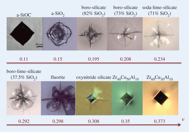
The volume of matter displaced on indentation needs to be accommodated within the semi-infinite material surrounding the indentation site. An analysis of this problem in the far field—i.e. far enough from the indentation process zone where different irreversible mechanisms (densification, shear flow and phase transformation) take place—can be limited to linear elasticity. By superposing the Boussinesq stress field originating from a point-load normal to the surface of a semi-infinite elastic body (Young's modulus, E, and Poisson's ratio, ν) [10] and a field (referred to as the ‘blister’ field) stemming from a strain nucleus built on a dilatation centre and a vertical compression force doublet [11], Yoffe [12] proposed a field that describes the various indentation cracking features remarkably well [13,14]. In this field ν, E and hardness (H) play key roles. Nevertheless, the large variation of ν, from 0.1 to 0.43, is primarily responsible for the dramatic changes in the indentation pattern (figure 1). Besides, although elastic moduli are strictly defined at the continuum scale (i.e. typically over 10 nm for a glass) and for small perturbations around equilibrium, an interesting outcome of these studies is that there is a remarkable correlation between the elastic properties (chiefly ν), the amount of densification or shear flow which might involve large strains, as well as the type and the extent of the microcracking pattern that results from the process [14]. This is because relatively open structures such as those of amorphous silica and germania usually come with a high degree of cross-linking (silica and germania glasses are based on corner-sharing tetrahedra) so that a strong resistance towards contraction in the transverse direction shows up in tension and a low Poisson's ratio (0.15 and 0.19, respectively) follows, whereas better packed structures are mostly associated with a smaller degree of atomic cross-linking (it is easier to pack rod- or sheet-like units than tetrahedra) so that local shear becomes easier and ν increases (in the extreme case of metallic glasses with transition metal host elements, ν reaches values as large as 0.45) [17,18]. Pressure and temperature have strong effects on the atomic network structure. In general, pressure increases the atomic packing density, while temperature tends to de-structure the network. In both cases, a rise of ν is noted. Indentation induces high pressure levels which are responsible for the alteration of the physical properties of the glass in a region beneath the indent. This makes the establishment of a pertinent constitutive law rather complicated, all the more so as shear seems to exacerbate the pressure effect in a way that is not elucidated yet.
Figure 1.
Glasses from different chemical systems indented for 15 s in ambient conditions using a Vickers diamond indenter. From top left to bottom right (indentation load is given in brackets): Si1O1.6C0.8 (196.2 N) [15], SiO2 (98.1 N), Si0.25B0.08Na0.03O0.64 (98.1 N), Si0.23B0.061Na0.06Ca0.003K0.031Ti0.003O0.609 (98.1 N), Si0.248Na0.086Ca0.037Al0.003Mg0.021K0.002O0.603 (standard window glass) (98.1 N), Si0.139Na0.023Ca0.056Mg0.026P0.003La0.024B0.098Ti0.023O0.608 (9.81 N), P0.04F0.36Al0.07Li0.03Mg0.02Ca0.04Sr0.05Ba0.02O0.37 (9.81 N), Sr12.73Si10O20.08N8.44 (4.91 N) [16], Zr0.4Cu0.5Al0.1 (98.1 N) and Zr0.6Cu0.3Al0.1 (98.1 N). (Online version in colour.)
2. The indentation process
The indentation process involves reversible and irreversible deformation components. The quantity of matter which flowed downward and gave birth to the residual stresses can be estimated from the imprint left once unloading is completed after the densification and isochoric shear flow parts are deduced. The elastic contribution can be estimated from the elastic recovery accompanying the unloading stage, while the densification and shear contribution can be deduced from a thermal treatment allowing for the recovery of the densified zone [2,19] and from the amount of matter which piles up on the indent sides, respectively (figure 2).
Figure 2.
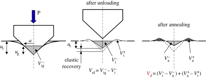
Schematic drawing of the indentation volume topological analysis by means of AFM, before and after annealing at 0.9 Tg for 1 h. Superscripts (−) and (+) refer to indentation and pile-up volumes, respectively. Subscripts ‘el’, ‘ig’, ‘i’ and ‘a’ denote the elastic recovery, the geometrical, the indent and the post-annealing volumes, respectively (recall that  ). (Online version in colour.)
(a). The elastic recovery
Following Stilwell & Tabor [20] and using the elasticity solution proposed by Sneddon [21] in the case of a rigid cone indenter, Lawn & Howes [22] obtained the following expression for the relationship between the recovered depth (displacement ur at centre) and the total penetration depth (ut at the centre at maximum load) (figure 2):
 |
2.1 |
where ψ is the apical angle of the axisymmetrical indenter (the equivalent cone for a Vickers indent corresponds to ψ=70.3°; this is the cone that would produce a circular imprint (radius a) of the same projected area and depth for a given load as for the Vickers indent).
At peak load, assuming that the indenter is perfectly rigid, the indentation volume (V−ig) corresponding to the region where there is contact between the indenter and the glass can be estimated from the geometry of the indenter and the penetration depth (ug), defined as being the depth of the indenter actually in contact with the substrate (figure 2):
 |
2.2 |
With  , equation (2.2) gives
 |
2.3 |
Although the residual indent exhibits a complex shape that prevents a straightforward geometrical relationship between the depth and the volume, to a first approximation, assuming that a is the same for both loaded and relaxed conditions (in agreement with experimental observations) the indentation volume after complete unloading is written as
| 2.4 |
where γ=ut/ug. So that
 |
2.5 |
Lawn & Howes [22] found the best fit to their data on recovery depth was with γ=0.91. However, it is noteworthy that γ is very sensitive to the constitutive stress/strain law. In the case of pure elasticity, γ=π/2, whereas γ=1 in the case of a rigid/perfectly plastic material without piling-up or when densification is the sole deformation mechanism (as in the case of weakly cohesive mousses). Sinking-in (γ>1) is common for polymers, whereas piling-up (γ<1) is usual for ductile metals. In the case of inorganic glasses, γ is found to increase almost linearly with ν [23]. γ approaches π/2 for chalcogenide and metallic glasses (where elasticity gives a major contribution to the indentation) but decreases as the silica content increases in silicate glasses to approximately 0.8 for amorphous silica (a-SiO2). For the studied glasses and using existing data for the indentation volume, the best agreement with equation (2.5) is met for γ=0.59 (figure 3).
Figure 3.
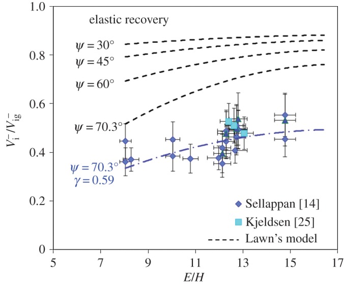
Elastic indentation volume recovery of oxide glasses with different E/H ratio (V−i and V−ig are the imprint volume after complete unloading and the geometrical volume of the imprint at maximum load). ψ is the apical angle of the conical indenter (the equivalent cone for a Vickers indent is characterized by ψ=70.3°). Hardness (Vickers test) was calculated using H=P/(2a2), where P (in newton) is the peak load applied on the indenter and a (in metre) is half the diagonal length. (Online version in colour.)
(b). The permanent deformation
Indentation involves stresses of the order of the material hardness, i.e. large enough to promote the densification of matter—both in the area of contact and in a region typically approximately 1/3 of the indentation size depth. This is because the disordered atomic structure of glass allows for a significant amount of free volume, especially in glasses with a large fraction of glass-forming elements, such as silica- or alumina-rich glasses. For a given glass composition, the free volume content increases with the rate at which the glass-forming melt is quenched. Indeed the instantaneous elastic response of the material to the sharp contact loading induces a contact stress as high as  [11,21], i.e. typically over 10 GPa for silicate glasses. The contribution of the densification process depends much on the glass composition and can be as high as 84% of the residual indentation volume in a-SiO2 and is less than 5% in the case of bulk metallic glasses [6,19]. For a window glass, it is typically close to 60%. The fractions of the indentation volume (permanent imprint) attributed to densification and shear, namely V
R and V
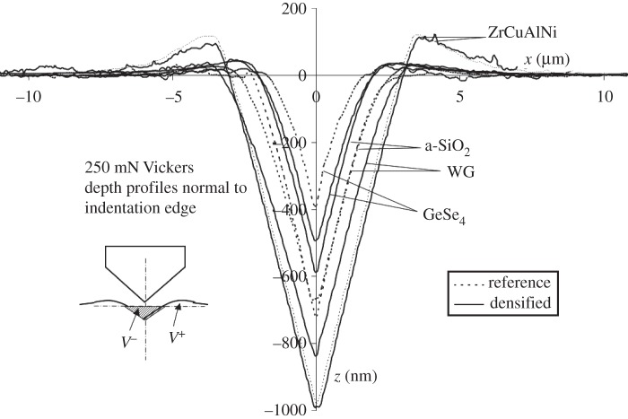
P (associated with the pile-up volume, V+, of matter in the vicinity of the indent), respectively, were quantitatively estimated using atomic force microscopy (AFM). Some typical indentation profiles normal to the indentation edges (i.e. where the piling-up of matter is the most pronounced) are shown in figure 4. The details of the experimental procedure are given in [6,14].
Figure 4.
AFM characterization of the indentation profiles through the centre of Vickers indents for a 250 mN load, normal to the edge (pile-up is less pronounced in cross sections containing the indent diagonals). Inset shows the V+ and V− volumes. (See [7] for details.)
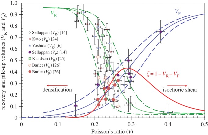
As expected, V R decreases monotonically as ν increases (figure 5). On the contrary, V P increases with ν and this can be viewed as evidence for more shear ductility at large ν combined with a decrease of the densification contribution. The indentation volume that remains once the densified and piled-up ones are deduced is supposed to correlate with the intensity of the stress field so that ξ=1−V R−V P is a composition-dependent parameter between 0 and 1 which plays a key role. ξ is found to exhibit a maximum of 0.42 at ν∼0.29. In figure 5, the data from Yoshida et al. [6], Kato et al. [24] and Sellappan et al. [14] were obtained on oxide glasses from various chemical systems including mainly silicates, borates and fluorites. Those from Kjeldsen et al. [25] (J. Kjieldsen 2014, personal communication) and Barlet [26] were obtained on sodium-aluminosilicate and on sodium-borosilicate glasses, respectively. Unfortunately, in spite of a clear overall tendency, there is no one-to-one relationship between V R (or V P) and Poisson's ratio. It is noteworthy that a bewildering range of data corresponds to ν between 0.2 and 0.3, i.e. precisely where most glasses are located! This shows the limit of what can be inferred from ν and will be discussed in §3a,b. Considering materials in general, two extreme cases are of particular interest: foams or materials based on cellular structural units for which ν is usually small (eventually negative), and ductile materials (including viscous liquids) such as rubber near Tg and pure metals with large atomic numbers (typically above 76) for which ν approaches 0.5 (ν∼0.44 for Au, Th, Pb). When you put your finger in a chocolate mousse or when you leave a footprint in mud, residual stresses are limited and no crack forms, yet the physics of the deformation process in both types of materials is very different: matter collapses in the first case inducing a local increase of the density while isochoric shear flow predominates in the second one. Interestingly, materials responding in very different ways (densification versus shear flow) to an indentation loading might exhibit a similar hardness value. Note, also, that the way a material responds to sharp contact loading depends much on temperature as is discussed in §3e. Clay is a microporous material having a softening temperature close to room temperature. Indenting clay in liquid nitrogen favours densification while at and above the softening point shear flow relays on. It is thus an excellent candidate as a ‘model’ material to reveal both deformation mechanisms in an unambiguous manner at a macroscale [27] (figure 6).
Figure 5.
Densification volume recovery and pile-up volume for Vickers indents on oxide glasses with different Poisson's ratio (ν). The dotted curves represent the experimental boundaries for both the densification and the pile-up volumes. The red curve (ξ) reflects the intensity of the residual stress field and is obtained from the average V R and V P ratios. (Online version in colour.)
Figure 6.
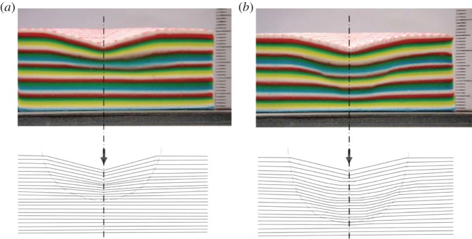
Vickers imprints performed with a 10 cm large metallic Vickers indenter on a sandwich material consisting of coloured layers of synthetic clay (Plasticine) (scale is indicated by the ruler on the right of the photographs). Note the change in the irreversible deformation mechanism with temperature, from (a) densification (T=208 K), with a clear decrease of the layer thickness to (b) isochoric sliding (T=297 K) with some localized shear displacement at the border of the process zone [27]. (Online version in colour.)
3. The driving force for indentation cracking
(a). Stress field and indentation cracking map
The volume of matter displaced on indentation needs to be accommodated within the semi-infinite material surrounding the indentation site. An analysis of this problem in the far field—i.e. far enough from the indentation process zone where different irreversible mechanisms (densification, shear flow and phase transformation) take place—can be limited to linear elasticity. By superposing the Boussinesq stress field [10] originating from a point-load normal to the surface of a semi-infinite elastic body and a field stemming from a strain nucleus built on three force dipoles (referred to as the ‘blister’ field) [11], Yoffe [12] proposed a field to describe the various indentation cracking features [13]. This field is expressed as
| 3.1 |
 |
3.2 |
 |
3.3 |
 |
3.4 |
| 3.5 |
where P is the indentation load and B is the strength of the blister field,
 |
where ξ accounts for the sensitivity of the material to densification and shear flow (see figure 5) and V−i is the indentation volume which can be estimated from the geometrical volume by means of equation (2.5).
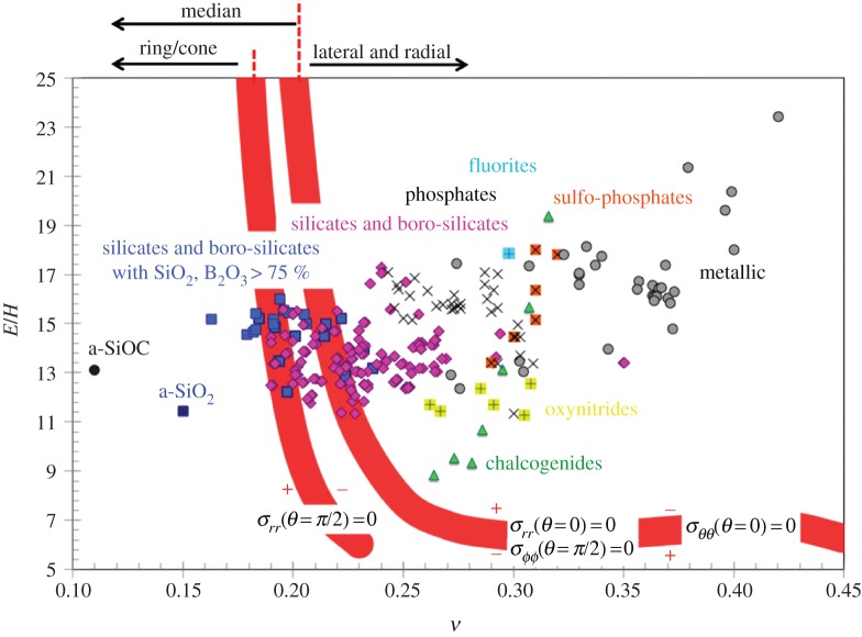
Ring, radial, lateral and median cracks (figures 1 and 7) are essentially driven by σrr(θ=π/2),σϕϕ(θ=π/2),σrr(θ=0) and σθθ(θ=0), respectively, in spherical coordinates, with origin on the surface at contact point, θ being the angle to the loading axis and ϕ the angle around this axis (hoop) (figure 8). The intensity of the blister field was discussed for glasses having different compositions by Sellappan et al. [14]. In the present work, the expression of the stress field ( ) is refined to account for the actual indentation volume after unloading by replacing the geometrical volume at peak load (upper bound for the indentation volume) by the volume after elastic recovery given by equation (2.5). Normalized to hardness (H), and taken at r=a (i.e. at the border of the imprint), these components are
 |
3.6 |
 |
3.7 |
 |
3.8 |
 |
3.9 |
Figure 7.
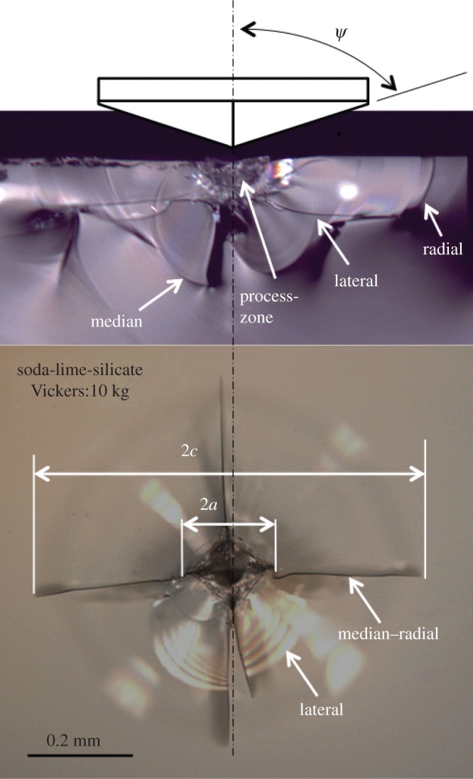
Illustration of the indentation cracks observed in a window glass post-Vickers indentation under a 98.1 N load. (Online version in colour.)
Figure 8.
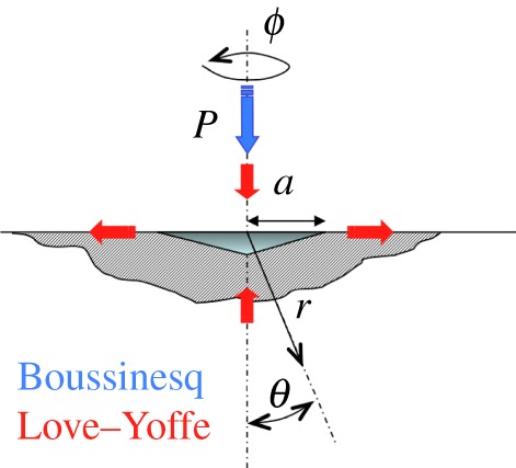
Schematic drawing of the spherical coordinate system centred at an indentation of characteristic lateral size a for a contact load P. (Online version in colour.)
Note that this stress field which arises on loading is load independent due to the geometrical similarity of the problem. Nevertheless, the situation is different during the unloading stage as the blister field strength (the terms in ξ in equations (3.6)–(3.9)) remains unchanged (due to the irreversible densification and to the permanent pile-up of matter) while the (elastic) Boussinesq field decreases linearly with P, so that microcracking can occur on unloading if the sign of a stress component changes from negative to positive. Being elastic by essence and ignoring the fine details of the physics of the deformation process, this field is inapplicable in the area adjacent to the contact. However, at a distance approximately a from the contact centre, the behaviour is believed to be essentially elastic (+damage) as the densification process zone is confined at r<a (see figures 6 and 10). The reason for taking r=a both in equations (3.6)–(3.9) and in figure 9 is simply for the sake of simplicity and normalization. Within this framework, equations (3.6)–(3.9) provide a simple tool to assess the sensitivity of a particular glass submitted to a sharp contact loading with an axisymmetric indenter (defined by ψ) to the various types of indentation cracking, where (E, H, ν, ξ) are key material characteristics, ξ being essentially related to ν. It is noteworthy that identical plastic zone boundaries were observed by Samuels & Mulhearn [28] for spherical and Vickers indenters of equal volume, so that at first sight, the indentation pressure underneath the indenter is assumed to be independent of indenter geometry. This result is corroborated by the calculation of the stress components resulting from Boussinesq and Hertz fields which are rapidly converging at depth larger than a (indentation size) [14,29].
Figure 10.
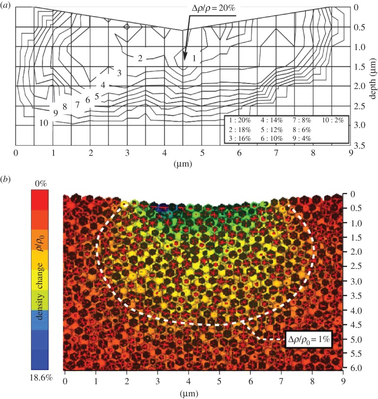
Cross sections (xOz plane) of vitreous silica post-Vickers indentation under 500 mN for 15 s. (a) Experimental results as obtained by Raman scattering spectroscopy by following the shift of the D2 band (approx. 600 cm−1) induced by the densification [36]; and (b) DEM–CNEM coupling numerical results [37]. Note that a 1% relative increase of the density corresponds to a pressure of about 8 GPa [38]. (Online version in colour.)
Figure 9.
Indentation cracking driving-force map. Stress components are taken at r=a for sake of simplicity. Recall that σrr(θ=π/2), σϕϕ(θ=π/2), σrr(θ=0), σθθ(θ=0) are the stress components governing the ring/cone, the radial, the subsurface lateral and the median cracks, respectively. Signs (−) and (+) indicate the area where the stress component is compressive and tensile, respectively. The thick red contour shows where the driving force is expected to vanish according to equations (3.6)–(3.9). The thickness of these contours reflects the experimental boundaries for V R and V P (figure 5). (Online version in colour.)
The combination of material characteristics which leads to the vanishing of a particular stress component and the region where this component is negative are of paramount interest in the search for crack-resistant materials. Because of the relatively large scatter of the data for each mechanism in figure 5, the frontiers between tensile (+) and compressive (−) areas as obtained from equations (3.6)–(3.9) by setting  are rather diffuse (thick red lines in figure 9).
In addition, the ease for the densification of matter beneath the indent can be discussed in the light of the hydrostatic part of the stress field (Trace  )
)
 |
3.10 |
The maximum shear stress can be assessed by taking the radius of the Mohr circle, (σI−σIII)/2, which is defined everywhere except for θ approaching π/2 where σϕϕ (=σII, the second principal stress), becomes smaller than σIII:
 |
3.11 |
Besides, the effect of the glass composition on the cone crack angle can be deduced from the calculation of the angle at which the principal stress σI reaches its maximum or from the trajectory of the minimum principal normal stress σIII. However, one must keep in mind that all information that can be deduced from this stress field is essentially qualitative for several reasons: (i) cracks as they develop strongly alter the stress field, (ii)  was derived on the basis of the initial stress-free and pristine material situation regardless of the necessary actualization of both the geometry of the domain and the material physical properties (e.g. densification is known to significantly alter the elastic properties), and (iii) the apparent hardness as measured by means of indentation method is known to change with the applied load—a decrease of H is mostly observed with an increase of P. For a-SiO2, it decreases from ≈11.3 to ≈6.3 GPa as the load increases from 10 mN to 1 N [30,31], and for a standard window glass, it changes from ≈6.3 to 4.5 GPa as the load increases from 10 mN to 10 N [14]; 32; this is the so-called indentation size effect (ISE) that is discussed below.
(b). Friction and indentation size effect
As the indentation load decreases, the indentation size decreases and both the area in contact between the indenter and the glass and the indentation volume decrease. But since the surface scales with a2, whereas the volume scales with a3, the surface to volume ratio increases. This observation led Li et al. to the conclusion that in metal [33] and in glasses as well [34] friction at the indenter–material interface is a major component of the ISE. On the contrary, the role of friction in the load-independent highest load regime is probably very limited. Another important observation stemming from a numerical study of bone tissue [35] is that friction greatly reduces the pile-up observed post-indentation. Therefore, the indentation load has a direct influence on the E/H ratio as well as on the pile-up contribution. In figure 9, data corresponding to the high load regime were used, whenever available, and whenever specified in the corresponding reference. In spite of these important sources of error, considering pure amorphous silica indented with a Vickers diamond at 500 mN load, the intensities of the densification in a cross section as obtained by Raman spectroscopy, by discrete element method (DEM) and by means of equation (3.10) are comparable (figure 10). The depths at which densification of 1% and 20% are achieved are approximately 3 and 1.5 μm, respectively, as estimated by Raman scattering [36]. A depth of approximately 4 μm is determined by DEM [37] for 1% densification, and depths of 3 and 2 μm are estimated for 1% and 20% densification, respectively, from the analytical expression of the stress field [39].
(c). The effect of indenter angle on the indentation response
Both the elastic recovery and the densification processes are significantly affected by the angle of the indenter. The larger the angle, the greater is the elastic recovery (figure 3). For a 30° indenter, the indentation volume after complete unloading is expected to represent more than 80% of the indentation volume at peak load (V−ig), whereas for a 70.3° angle, the recovery is between 50 and 70%, depending on the E/H ratio. Regarding densification, and limiting the analysis to the hydrostatic stress component to a first approximation, the Boussinesq field results in σh(r=a,θ=0)=−(1+ν)H/3, which is thus negative whatever the glass composition. In contrast as soon as the blister field is added, a critical ν value shows up for a given cone angle beyond which σh changes from negative to positive (figure 11). Although the magnitude of σh in the range where it is positive as well as the critical ν values are questionable because of the assumptions underlying the elaboration of the blister field, the trend is clear: densification is favoured at small ν and large indenter angle (ψ). The theoretical prediction obtained from equation (3.10) regarding the influence of the indenter tip sharpness corroborates the observations made by Yoshida et al. [40] and Gross [41] who have shown that as indents are made with sharper tips, the deformation response evolves towards a larger shear contribution, higher residual stresses, better defined median/radial cracks emanating from the corner of the indent impression and subsurface lateral cracking. In the case of a-SiO2 for instance, ring/cone crack-free indents resembling those observed in a window glass were obtained by Gross [41] with indenter angles (ψ) smaller than 60°, consistent with the transition of σh from negative to positive which is noted at ν∼0.17 for ψ=60° in figure 11. Regarding the ring/cone cracking features (angle, length), there seems to be little effect of the indenter geometry [42].
Figure 11.
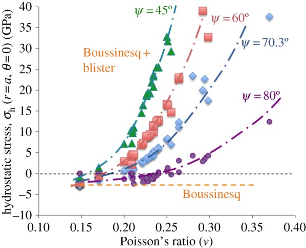
Dependence of the apical angle of the conical indenter on the hydrostatic stress for glasses with different Poisson's ratio. A Vickers indenter corresponds to an equivalent cone indenter with approximately 70.3° apical angle. Dotted lines are guides for the eyes. The solid marks are associated with the actual properties (E, H, ν, ξ) of series of glasses [14,39]. (Online version in colour.)
(d). The effect of high pressure
To the best of the author's knowledge, there is no report on the indentation behaviour of glass under hydrostatic pressure although this might open new perspectives in geological sciences and in vulcanology for instance. All investigations are performed post-decompression and reveal significant differences in the indentation behaviour after high pressure treatments (typically larger than 15 GPa) in comparison to the behaviour of the pristine glass (prior to the treatment). High pressure experiments lead to denser materials (even after unloading), to an extent that was found to scale with Poisson's ratio of the glass [38] because of the intimate relationship existing between ν and the atomic packing density [18,43]. Hence, there is less room for further indentation densification after a high pressure treatment. Both experiments [7] and molecular dynamic simulation [44] pointed to a shift to more pile-up of matter at the vicinity of the imprint and thus shear flow after high pressure treatments and, as a matter of fact, ν is mostly larger in the treated glass than in the pristine sample [7]. For instance, in the case of a-SiO2, V+/V− increases from approximately 0.17 to 0.77 after a treatment at 25 GPa for 1 h and subsequent Vickers indentation under 250 mN (figure 12) and ν increases from 0.15 to approximately 0.252, so that the densified glass becomes more sensitive to radial/median cracking, as was evidenced in a sodium silicate glass densified up to 5 GPa [47]. In the meantime, the E/H ratio increases from 8.9 to 9.5 thanks to a large increase of E in comparison to H. A similar trend was observed in soda-lime-borate glass densified up to approximately 5% at 0.57 GPa [48]. In this latter case, ν increased from approximately 0.268 to approximately 0.276 and the increase of the c/a ratio (crack length/indentation size) (figure 7) from 2.5 to 3.3 under 9.81 N load indicates a greater sensitivity to radial/median cracking. However, in soda-lime-borate glass, a slight decrease of the E/H ratio from 13.5 to 11.8 was noted and is due to hardness being more improved than Young's modulus by the treatment. As expected, the influence of pressure treatments remains very limited in the case of metallic glasses where a transition metal is the major host element and especially in those with large ν (Pd-, Pt-, Zr-, Cu-based) thanks to their high atomic packing density.
Figure 12.
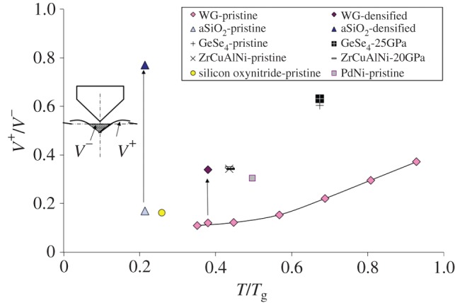
Influence of temperature on the V+/V− volume ratio which reflects the importance of shear in the deformation process. Data extracted from [7,14,45,46]. (Online version in colour.)
(e). The effect of temperature
The resistance of glass to indentation cracking and to cracking in general depends much on temperature. What seems to matter is how far the testing temperature is from Tg and how fast the glass softens on heating—which corresponds to the concept of ‘strong’ or ‘fragile’ liquid introduced by Angel [49]. In this regard, increasing the temperature from below Tg to favour viscous flow (and associated time-dependent relaxation processes) is very similar in its consequences to varying the composition to decrease Tg and testing in ambient conditions. The increase with temperature in the amount of matter piling up at indents is pronounced. For a soda-lime-silica glass (window glass), the V+/V− ratio increases from approximately 0.1 to approximately 0.4 as T/Tg increases from 0.4 to 0.9. A similar trend is observed when the ambient behaviour of glasses with relatively high Tg such as a-SiO2 or silicon oxynitride glasses is compared with that of low Tg glasses such as chalcogenide glasses, so that T/Tg varies from 0.2 to 0.7 (figure 12). Although changes in the indentation site topology are the most obvious effect of temperature, heating has several—perhaps less visible but determining—effects on the indentation problem. For instance, most glasses experience a decrease of their hardness upon heating which is more dramatic than the corresponding decrease of the elastic moduli (especially the shear modulus). Consequently, the E/H ratio increases with temperature, and so does the intensity of the residual stress field, and thus the driving force for cracking (figure 13a). The increase of the E/H ratio is particularly large when heating is accompanied by stiffening (this is the so-called ‘elastic anomaly’ observed for a-SiO2). ν is also inclined to increase with temperature, but to a lesser extent than beyond Tg where the rapid loss of structure of the liquid induces a sharp drop of the shear modulus (figure 13b). Consequently, and as predicted by the indentation cracking map (figure 9), the formation of radial/median cracks as opposed to the ring/cone cracking system is more and more favourable as T progressively increases from below Tg, at least on the basis of a simple elastic approach of the far-field stress. This was experimentally verified in a few cases, mostly for a-SiO2 and soda-lime-silicate glasses (figure 14) [50–53]. As temperature increases from ambient to 673 K, the ring/cone cracks observed in a-SiO2 disappear to the benefit of the radial/median pattern (figure 14a,b). Conversely, as temperature decreases, E/H as well as ν decrease and shear flow becomes less and less significant and eventually disappears at 77 K as observed by Kurkjian et al. [5] in the case of a-SiO2 and a soda-lime-silica glass, for which the E/H ratio decreases from 8 and 10 to 3 and 6.3, respectively, as T decreases from room temperature to 77 K. Interestingly, as will be discussed in §3f, there seems to be also a correlation between the cone crack angle and ν. The concomitant increase of the E/H ratio results in radial/median cracks to grow on heating in a window glass (figure 14c–e). As a matter of fact, the soda-lime-silicate glass seems more damaged at 473 K than at ambient (figure 14d) [52]. Nevertheless, viscous flow takes over at higher temperatures, and especially on approaching Tg which corresponds to a characteristic relaxation time constant of the order of a minute, i.e. comparable to the time scale of an indentation experiment. In the present case visible microcracks disappeared in the 723–753 K range (figure 14e,f). A study focused on the brittle-to-ductile transition in a similar glass showed that ductility appears at temperatures from 723 to 823 K as the loading rate increases from approximately 1 MPa.√m s−1 to 10 MPa.√m s−1 [54]. The consequences of heating a glass on its response to a sharp contact loading are thus mainly threefold: (i) a change of the deformation mechanism from densification to isochoric shear flow, (ii) an increase of the intensity of the residual stress field up to say T/Tg∼0.9, and (iii) a disappearance of visible cracking corresponding to the rate-dependent brittle-to-ductile transition appearing in a temperature range almost coincident with the Tg range.
Figure 13.
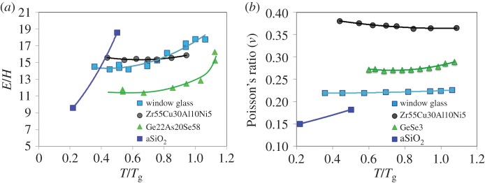
Influence of temperature on (a) the Young's modulus/hardness ratio (data on GeAsSe and ZrCuAlNi glasses from [50]) and (b) Poisson's ratio (adapted from [17]). (Online version in colour.)
Figure 14.
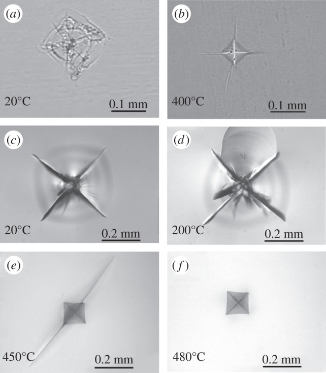
Influence of temperature on the Vickers indentation cracking pattern for vitreous silica [51] under 5 N load at (a) 20°C and (b) 400°C, and for a soda-lime-silica glass (planilux, Saint-Gobain) [52] under 49 N load at (c) 20°C (ν=0.234, E/H=12.5), (d) 200°C, (e) 450°C (ν=0.24, E/H=20) and (f) 480°C.
(f). What can be inferred from the Boussinesq–Love–Yoffe stress field?
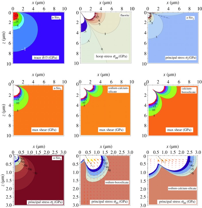
The stress distribution beneath the contact area in planes containing the load axis is illustrated in some cases of special interest in figure 15. It was shown earlier [38] that a pressure of approximately 8 GPa is required to achieve about 1% persistent densification in a-SiO2. According to the hydrostatic stress component analysis (top left contour plot), this would occur at a 2.7 μm depth for a 500 mN load which agrees quite well with the experimental Raman densification map (approx. 2.5 μm) and reasonably well with the DEM simulation (figure 10). The hoop stress component (σϕϕ) divides the semi-infinite space into two regions, one in compression (σϕϕ<0) centred on the Oz axis and one in tension (σϕϕ>0) on approaching the surface, the latter being responsible for the radial cracks observed at the surface. The boundary surface where the hoop stress vanishes is located at an angle from the surface which increases with ν, so that the tensile region is found to grow with ν and is particularly large in the case of the fluorite glass (ν=0.298). Note that the form drawn by the isocontours in the tensile region is reminiscent of the shape of the radial cracks (figure 7). The maximum tensile stress corresponds to the largest principal value of the stress tensor (σI) and the spatial distribution of this principal normal stress is illustrated in the case of a-SiO2 (top right plot in figure 15).
Figure 15.
Stress distribution in sections containing the loading axis on loading with an axisymmetrical indenter (ψ=70.3°) at a 500 mN load (as for figure 10). Isocontours for each stress component indicate the stress intensity in GPa. The second row corresponds to glasses with the following properties (from left to right): ν=0.15, E/H=8.7; ν=0.234, E/H=73.3/6.3; ν=0.292, E/H=104.4/8.2. The bottom row shows the σIII stream vectors in cases where cone cracking is mostly observed, with increasing Poisson's ratio: ν=0.15, 0.195 and 0.234 from left to right, respectively. (Online version in colour.)
Cone cracks are supposed to initiate from critical flaws located beneath the contact area in planes orientated close to 45° from the surface where the shear stresses are the greatest and to extend along a path following the maximum σI values, i.e. along the trajectory of the minimum principal normal stress (σIII) (bottom plots in figure 15) [55,56]. However, cone-cracking angles (to the surface) predicted this way are mostly in poor agreement with the experimental values. As pointed out by different authors [57,58], the original stress field is continuously modified as cracks extend, and the formation and growth of cone cracks themselves alter the trajectories. As underlined by Kocer & Collins [58], cracks propagate along paths resulting in the maximum release of strain energy which do not necessarily coincide with the normal to the maximum pre-existing tensile stress. Tumbajoy-Spinel et al. [59] confirmed indeed using an extended finite-element method (X-FEM) that the stress field ahead of the crack tip—and in particular the minimal principal stress—evolves on crack extension, so that α (see figure 16) is found to decrease from approximately 35° to approximately 24.5° for a soda-lime-silicate (ν=0.22). Using FEM and a remeshing technique [58], DEM [37] or an X-FEM method [59], the geometrical characteristics of the Hertzian cone cracks observed in brittle materials could be nicely reproduced. One of the most interesting features of cone cracking is that it seems to be very sensitive to Poisson's ratio. For instance, the cone angle (α in figure 16) decreases as ν increases. This is corroborated by the analytical modelling (equations (3.6)–(3.9)) where the ‘initial’ path predicted for the cone crack can be obtained by drawing the σIII stream vectors, (where σI acts normal to the stream lines). The cone crack is supposed to follow the stream line corresponding to the minimum σIII (thus maximum σI) which is represented by a black dashed line in the bottom plots in figure 15. Experimentally, we observed α∼41° and 34° for a-SiO2 (ν=0.15) and a borosilicate glass (ν=0.195), respectively, for a 98.1 N Vickers indent (figure 16). This is in good agreement with the values obtained by Wilantewicz & Varner [60] in a-SiO2 with a 9.81 load (α∼42°–44°) and by Bertoldi & Sglavo (α∼35°–36°) [42] and by Chaudhri & Kurkjian (α∼33.5°) [61] for commercial borosilicate glasses with ν∼0.2. For a soda-lime-silica glass (typical window glass composition), the cone angle α is approximately 22° [55,62]. For alumina (ν∼0.24) and an Al2O3/SiC composite (ν∼0.25), α∼26° and 28°–31°, respectively [63]. For vitreous carbon (ν∼0.27–0.29) the angle the cone (ball indentation test) makes with the surface is 22.5° on average [64]. Fischer-Cripps & Lawn [65] obtained a cone angle of 19° for a silicon nitride ceramic (ν∼0.27). Therefore, as was noted by Bertoldi & Sglavo [42], although the angle is not severely affected by the indenter geometry, it is very sensitive to the glass composition and especially to Poisson's ratio. Note that the effect of ν on α was already mentioned by Lawn et al. [55] who noted that ν has a profound influence on the stress field and further attempted to ‘tune’ the ν value to get their modelling to match better with the experimental results for α.
Figure 16.
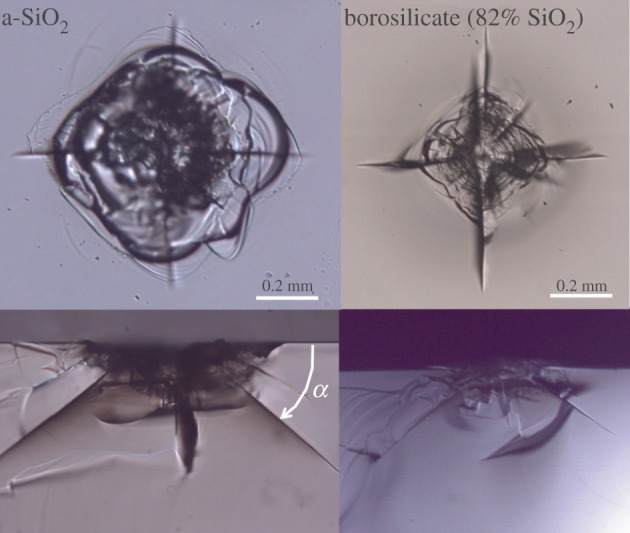
Top and side views of Vickers indents obtained under a 98.1 N load in a-SiO2 (ν=0.15) and a sodium-borosilicate glass (approx. 5 mol% Na2O, ν=0.195). (Online version in colour.)
There is strong evidence for the fact that in glasses susceptible to experience a density increase (be it due to a high pressure treatment or to a local indentation), densification is assisted by the presence of a concomitant shear stress component [66,67]. It turns out that the profiles for the shear isocontours change much with ν, and that the overall region associated with a shear stress larger than a given value extends with ν, especially along the xy-plane (surface). The maximum shear stress (equation (3.11)) is represented for three different glasses in figure 15 (second row).
4. Search for a constitutive law
A better description of the indentation problem in glass requires a specific, physically sound, constitutive law for the mechanical behaviour of this particular class of materials. This raises various kinds of difficulties, at the fundamental level of the physics of the deformation mechanisms, and at the practical level of the implementation in FEM software. However, it is a necessary step towards the numerical modelling and the simulation of complicated processes such as scratching, grinding, and polishing. Accounting for the observation by Mackenzie & Laforce [66] and Uhlmann [67] who suggested that shear favours densification under hydrostatic pressure, Imaoka & Yasui [68] in a finite-element analysis of glass indentation proposed to combine the shear and the hydrostatic parts of the indentation stress, introducing a densification factor and a von Mises equivalent shear stress in an additive yield criterion. This approach was further developed by Lambropoulos et al. [69] who proposed a yield function  that ressembles the Mohr–Coulomb law used in soil mechanics (including granular media) where the local shear is represented by τmax, or the Drucker–Prager criterion used in structure mechanics where an equivalent shear stress is considered, but in which both shear and pressure work in favour of yielding (unlike in soil mechanics):
| 4.1 |
where σh is the hydrostatic stress (mostly less than 0 beneath the contact area), τe is an equivalent shear stress (for instance,  , where
  is the deviatoric stress), σo is the critical yield stress (pressure) in absolute value, and ζ determines the sensitivity to the shear component.
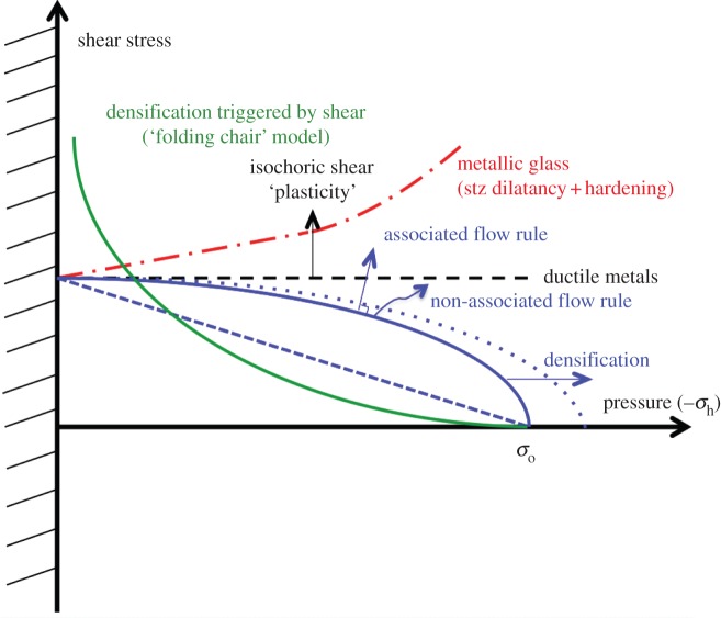
τe is smaller than τmax which represents the maximum shear stress occurring on a particular plane at the point of interest but is more representative of the shear level at this point. For example, in the case of a-SiO2, densification starts at pressure of the order of 7 GPa and almost saturates at pressures more than or equal to 22 GPa [70], so that σo evolves from 7 and 22 GPa on densification (this entails the occurrence of strain hardening) but then densification almost saturates. Lambropoulos proposed that ζ∼1.6–2. In order to account for the progressive decrease of the densification level observed by Raman scattering spectroscopy with the increase of the distance from the indentation area, Kermouche et al. [71] inspired by the Shima–Oyane model for the compaction of porous metal [72] proposed a variant of the Drücker–Prager criterion where the square of shear and hydrostatic components are considered, so that the yield surface is represented by an elliptic curve (blue curve in figure 17). The increase of σo as the glass densifies simply stems from the fact that densification is a bounded process and is more and more difficult as the density approaches the ‘saturation’ plateau (located at approx. 22% and 7% relative density changes for a-SiO2 and a standard window glass, respectively). Equation (4.1) might be the source of several misunderstandings and is thus questionable. For instance, (i) it suggests a strong similarity between the glass behaviour and the flow of granular media or the compaction of powder, yet in these latter cases sliding requires some local temporary volume expansion (so-called Reynolds dilatancy) so that pressure (less than 0) and shear do not work together, in contrast with the case of silicate glasses where shear seems to promote densification; and (ii) the increase of the critical yield stress upon deformation might be viewed as a hardening process similar to those observed in the plasticity of metals whereas it simply derives from the kinematically bounded nature of the densification. But the most questionable issue is in the implicit choice for an additive contribution of shear and pressure, where for example shear would itself be able to induce a permanent strain in the absence of any pressure, provided ζτe=σo, which does not sound very realistic in the case of glasses such as a-SiO2 where densification contributes to over 80% of the permanent deformation. An alternative proposition in line with the schematic drawing proposed by Mackenzie [73] would consist in giving pressure to the role of a trigger in a process involving the entanglement of structural units of the glass network essentially driven by shear. This mechanism could resemble the one by which a folding chair is folded hence reducing the space it occupies. The ‘folding chair’ yield criterion could be written as
| 4.2 |
where ζ′(τe)≥0 and ζ′(0)=0.
Figure 17.
Yield surfaces as schematically drawn according to the various possible expressions proposed for the constitutive law of the mechanical behaviour of glass. (Online version in colour.)
A simple form for the shear function could be ζ′(τe)=|τe|/τn, where τn is a normalizing constant while σo depends on the amount of densification. Equation (4.2) might suffer from some technical problems (such as the implementation in FEM software) and fundamental issues (the form is nonlinear). To complete the constitutive model, the increase of the densification threshold as densification proceeds should be accounted for. Therefore, σo should depend on the amount of densification given by Trace  , where
  is the permanent strain tensor. Note in figure 17 that according to the ‘folding chair’ model, a small amount of shear allows for a substantial decrease of the pressure level required for densification, but that in the absence of pressure, shear would not suffice by itself to induce densification (or permanent flow). The underlying physics of the ‘folding chair’ model results in a concave shape for the τ−σh yield criterion, as opposed to the classical Drücker–Prager law where a closure cap terminates a convex curve. A concave shape is consistent with the experimental observations by Uhlmann [67] who showed that a relatively small shear contribution allows for a significant reduction of the necessary pressure to achieve densification.
Another significant problem is the evolution of the elastic characteristics on densification. This issue was addressed in a study focusing on the modelling of the densification process in a-SiO2 [74] which demonstrated that accounting for the evolution of the elastic moduli has a marked effect on the result of the modelling. In the case of Vickers, Berkovich or cube-corner indenters, densification is also promoted in regions in contact with the indenter edges, as was shown by Ji et al. [70] in the case of Vickers indenter.
Another crucial remaining issue concerns the direction of the flow vector with respect to the yield surface. An associated flow rule (vector normal to the yield surface) would not account for the densification under pure hydrostatic pressure in the case of equation (4.1), but would for the elliptical model. Nevertheless, in the latter case, isochoric flow would occur in the absence of hydrostatic pressure. Indeed, this is the physics of the flow process that matters and the permanent deformation of glass can hardly be described within a general ‘plasticity’ framework. There are essential differences in the physics of flow of glasses depending on the chemical system. Metallic glasses might exhibit some similarities with granular materials and behave according to constitutive laws inspired by those used in soil mechanics. On the contrary, silica glass essentially flows thanks to the ease for densification of the atomic network, and there is little room for an isochoric process which would be predicted on the basis of an associated flow rule using the elliptical criterion, unless perhaps if viscoplasticity comes into play. Besides, once the relative contributions of shear and pressure within the constitutive law are elucidated, the dependence of the spatial distribution of both stress components (figure 15) on the glass physical properties in the case of an indentation loading will still have a strong influence on the characteristics of the indentation site, and in particular on the residual stress field.
5. Perspectives
(a). Fracture toughness determination
Indentation cracking methods aimed at evaluating fracture toughness are based on the estimation of the residual stress field at indentation sites. Following Bishop et al. [75], who suggested that the stress distribution under a conical indenter might be approximated by that of a spherical cavity under pressure, Marsh [76], and later Johnson [77], taking advantage of known elasto-plasticity solutions [78] for cavity expansion induced stress field, proposed an expression for the mean contact pressure as a function of Young's modulus, Poisson's ratio and yield stress. All these models, and the subsequent developments by Lawn et al. [79] have in common the assumptions of volume conservation through plasticity, and of equality between the volume displaced by the indenter and the indentation core volume. Hill's analysis is based on Tresca's yielding criterion and provides a relationship between the plastic zone size (b), the radius of the cavity (a) and E/H. After simplification, Lawn et al. [79] proposed that b, normalized to the indentation size (a) varies as (E/H)m, with m∼1/2 affording a good approximation. Further assuming that the indentation volume (scaling with a3) coincides with the elastic perturbation spread over the plastic zone (volume V), the volume change (ΔV) is expressed as  and the resulting residual stress scales with K(H/E)3/2, where K is the bulk modulus. This approach was found quite successful to describe the indentation cracking behaviour of ceramics and allowed one to set expressions for fracture toughness (KIc) from E, H, P and indentation crack length (see Ponton & Rawlings [80] for a review). Nevertheless, it raises serious problems in the case of densifying materials or for ductile materials where the piling-up of matter is observed in the vicinity of the indent. Most glasses behave according to a combination of densification and pile-up. The affected zone volume (V) might be very different for glasses having similar hardness and Young's modulus depending on their respective abilities for densification and shear flow. Besides, in cases where densification is very significant, radial/median cracks are very limited (ΔV does not scale with a3 anymore) and indentation cracking methods result in KIc values much different from those measured by self-consistent methods [81]. Silica-rich and borosilicate glasses fall into this category. A factor between 0 and 1 can be introduced in Hill's and Johnson's models [77] to limit the volume contributing to the expansion of the indentation core to a fraction of the indent volume. For instance, this was attempted by accounting for the elastic recovery and the pile-up of matter by Feng et al. [82] and a good agreement between experiments and finite-element modelling was obtained in the case of perfect elasto-plastic materials (i.e. not for glass!). However, this factor depends much on the material composition. Yet the use of a classical plastic yield criterion still sounds inappropriate in view of the physics of densification which is a kinematically bounded process and implies strain-hardening, as well as concomitant changes of the elastic moduli. Besides, an Hill–Eshelby-type expansion cavity model gives by construction centrifuge forces, or in other terms the cavity induces radial compression on the surrounding matrix (with the exception perhaps of ellipsoidal inclusions with much smaller thickness (z-axis) in comparison to their xy plane size [83]). Therefore, such expansion cavity models seem unable to account for the opening of lateral cracks due to a positive normal σrr(θ=0) stress component, unlike the Love–Yoffe–Boussinesq model. This latter model was recently revisited and some refinement was attempted in the light of experimental results [84]. The recently obtained data regarding densification and shear-flow phenomena in glasses are very encouraging and open new realms of possibilities for the search of sensible fracture toughness expressions dedicated to this class of materials. Nevertheless, this is going far beyond the scope of this article.
(b). Towards glasses with a better surface damage resistance
So far most mechanical studies of indentation problems in glass have not paid much attention to Poisson's ratio, or they have assumed its value does not change much through the various glass systems. Yet ν has a pronounced influence on the stress field associated with contact mechanics problems, both directly through the analytical expressions stemming from elasticity theory, and in the physics of the deformation processes occurring beneath the contact area. Furthermore, ν varies dramatically with composition, as well as with temperature and pressure, and might also be affected by the environment.
For instance, Bertoldi & Sglavo [42] observed a transition from ‘normal’ (i.e. radial/median) to ‘anomalous’ (i.e. ring/cone) cracking when a sodium-borosilicate glass was indented in water instead of in silicone oil and suggested that the depletion of sodium—and the concomitant decrease of ν—due to water corrosion at the surface and within the crack front could be the reason for this evolution. A similar transition was already noted by Wagner 85 for borosilicate glasses with decreasing Na2O content. Recall that a decrease in Na2O content results in an increase of the trigonally coordinated boron atom (BIII) sites, a decrease of the atomic packing density and a decrease of ν. It was demonstrated by Kato et al. [24] that densification is enhanced by BIII in comparison with BIV. Indeed, BIII is associated with both a more open (lower Cg and ν) and more compliant (smaller elastic moduli) structure which is thus a favourable situation to enhance the indentation cracking resistance. Glass compositions which are expected to result in small amounts of non-bridging oxygen such as a-SiO2, a-GeO2 or boroaluminosilicate glasses where nearly all boron atoms are trigonally coordinated promote densification and increase the resistance to residual stress driven cracking. However, very high levels of densification which correspond to Poisson's ratio below say 0.2 lead mostly to the formation of ring-cone cracks at moderate loads and are often associated with glasses that are not easy to process (high melting points and high viscosity). Oxide silicate glasses mostly contain alkali and alkaline earth cations which ease melting and confer on the glass desirable characteristics in terms of water-corrosion resistance, refractive index, thermal expansion, thermal conductivity, production cost, etc. Most of these secondary oxides result in the occurrence of non-bridging oxygen ions. On the one hand, this makes the atomic network more compliant and increases the atomic packing density. On the other hand, this leads to an increase in ν [17] that is believed to favour shear deformation [3,4] but reduces the room for densification. This rise of ν is mostly detrimental up to approximately 0.29 (figure 5) as it results in an increase of the residual stresses. Only for glasses with ν over say 0.35 would this transition from densification to isochoric shear induce a ductile behaviour. As a matter of fact, silicon oxynitride glasses with ν typically as large as 0.3 [16] and in spite of an exceptional mechanical performance (values of E as large as 150 GPa are common for rare-earth-containing silicon oxynitride glasses) are very sensitive to radial-median cracking (figure 1).
In order to reduce the intensity of the stress field that builds up on indentation, and especially the blister field, it is inferred from the physics of the permanent deformation processes (figure 5) that Poisson's ratio in the 0.25–0.33 range should be avoided, unless the E/H ratio is smaller than say 7 (figure 9). There are glasses with ν larger than 0.33, for instance in metallic systems [86], but also possibly in oxynitride ones. In such materials, shear plasticity is promoted and favours a ductile behaviour. The fracture energy of bulk metallic glasses with ν>0.32 exceeds that of oxide glasses by 2–4 orders of magnitude [87]. This is, in technical terms, another view of resilience. A regain of resilience is thus expected at large ν.
In view of their resistance towards corner cracks (i.e. radial-median), four groups of glasses can be distinguished, namely:
— resilient glasses, for 0.1≤ν≤0.20,
— semi-resilient glasses, for 0.20≤ν≤0.25,
— easilydamaged glasses for 0.25<ν<0.33, and
— highly resilient for 0.33<ν.
According to the indentation cracking driving-force map (figure 9) among the considered glass chemical systems fluorite and sulfophosphate glasses, combining relatively large ν and E/H ratios will develop large stresses and are actually poorly resistant towards the formation of radial-median cracks. Interestingly, there are compositions in silica-rich alkali–alkaline earth silicate and in borosilicate glasses for which the stress field is expected to remain very small. It turns out that the so-called ‘less brittle’ glasses developed in the 1990s by Sehgal & Ito [88], with E/H∼14.7 and ν∼0.18 are precisely in the red coloured areas corresponding to the zero-stress contours for σrr(θ=π/2) and in the compressive side for σrr(θ=0) and σϕϕ(θ=π/2).
The effects of temperature and pressure are also worth being investigated. The study of glasses from different chemical systems also reveals that there is no one-to-one relationship between hardness and brittleness. There are rather soft glasses such as chalcogen-rich chalcogenide glasses (as exemplified by GexSe1−x and GexS1−x glasses with x≥0.8) which behave in an extremely brittle fashion (KIc<0.2 MPa √m), and relatively hard glasses such as oxynitride ones that exhibit a fracture toughness as high as 1.4 MPa √m, i.e. twice as high as that for a standard window glass. Fracture toughness as estimated from the indentation crack length is a questionable method when it is realized that the extension of densification and shear flow greatly differ from one glass to the other and as soon as changes in ν come into play.
In conclusion, beside the known situations where either densification or isochoric shear flow are favoured, new realms of possibilities would stem from the design of multiphase materials where both phases would contribute in relaxing the contact stresses in different ways. Phase-separated glasses, glass ceramics or glass matrix particulate composites are promising materials in this regard, as far as Poisson's ratio is made a special point of focus. The different scales at which innovative strategies can be developed to improve glass strength and toughness were discussed recently by Wondraczek et al. [89] in the light of the recent progress in atomistic modelling, topological description of the glass network (including long-, medium- and short-range effects) and surface treatments.
Acknowledgements
I am indebted to A. Moréac and to Dr J. P. Guin for the Raman scattering mapping at indentation site (figure 10a) and the AFM observations and analysis (figure 4), respectively, and to J. C. Sangleboeuf for stimulating discussions all along with this project. Special thanks to all PhD students and post-docs with whom I enjoyed working in the area of ‘glass indentation’ in the last 15 years at LARMAUR (now Glass Mechanics Department at IPR) and who gathered the data that are quoted in this paper.
Funding statement
The European Research Council is greatly acknowledged for the Advanced grant no. 320506 (DAMREG) of the 7th framework programme ‘Ideas’.
References
- 1.Marsh DM. 1964. Plastic flow in glass. Proc. R. Soc. Lond. A 273, 420–435. ( 10.1098/rspa.1964.0114) [DOI] [Google Scholar]
- 2.Neely JE, Mackenzie JD. 1968. Hardness and low temperature deformation of silica glass. J. Mater. Sci. 3, 603–609. ( 10.1007/BF00757906) [DOI] [Google Scholar]
- 3.Peter KW. 1970. Densification and flow phenomena of glass in indentation experiments. J. Non-Cryst. Solids 5, 103–115. ( 10.1016/0022-3093(70)90188-2) [DOI] [Google Scholar]
- 4.Ernsberger FM. 1977. Role of densification in deformation of glasses under point loading. J. Non-Cryst. Solids 25, 293–321. ( 10.1016/0022-3093(77)90096-5) [DOI] [Google Scholar]
- 5.Kurkjian CR, Kammlott GW, Chaudhri MM. 1995. Indentation behaviour of soda-lime-silica glass, fused silica, and single-crystal quartz at liquid nitrogen temperature. J. Am. Ceram. Soc. 78, 737–744. ( 10.1111/j.1151-2916.1995.tb08241.x) [DOI] [Google Scholar]
- 6.Yoshida S, Sanglebœuf JC, Rouxel T. 2005. Quantitative evaluation of indentation-induced densification in glass. J. Mater. Res. 20, 3404–3412. ( 10.1557/jmr.2005.0418) [DOI] [Google Scholar]
- 7.Rouxel T, Ji H, Guin JP, Augereau F, Rufflé B. 2010. Indentation deformation mechanism in glass: densification versus shear flow. J. Appl. Phys. 107, 094903 ( 10.1063/1.3407559) [DOI] [Google Scholar]
- 8.Perriot A, Vandembroucq D, Barthel E, Martinez V, Grosvalet L, Martinet Ch, Champagnon B. 2006. Raman microspectroscopic characterization of amorphous silica plastic behavior. J. Am. Ceram. Soc. 89, 596–601. ( 10.1111/j.1551-2916.2005.00747.x) [DOI] [Google Scholar]
- 9.Deschamps T, Martinet C, Bruneel JL, Champagnon B. 2011. Soda-lime silicate glass under hydrostatic pressure and indentation: a micro-Raman study. J. Phys. Condens. Matter 23, 035402 ( 10.1088/0953-8984/23/3/035402) [DOI] [PubMed] [Google Scholar]
- 10.Boussinesq J. 1885. Applications des potentiels aÌ l'étude de l'équilibre et du mouvement des solides élastiques. Paris, France: Gauthier-Villars. [Google Scholar]
- 11.Love AEH. 1927. A treatise on the mathematical theory of elasticity, p. 127 New York, NY: Dover Publications Inc. [Google Scholar]
- 12.Yoffe EH. 1982. Elastic stress fields caused by indenting brittle materials. Phil. Mag. A 46, 617–628. ( 10.1080/01418618208236917) [DOI] [Google Scholar]
- 13.Cook RF, Pharr GM. 1990. Direct observation of indentation cracking in glass and ceramics. J. Am. Ceram. Soc. 73, 787–817. ( 10.1111/j.1151-2916.1990.tb05119.x) [DOI] [Google Scholar]
- 14.Sellappan P, Rouxel T, Celarie F, Becker E, Houizot P, Conradt R. 2013. Composition dependence of indentation deformation and indentation cracking in glass. Acta Mater. 61, 5949–5965. ( 10.1016/j.actamat.2013.06.034) [DOI] [Google Scholar]
- 15.Moysan C, Riedel R, Harshe R, Rouxel T, Augereau F. 2007. Mechanical properties of a polysiloxane-derived SiOC glass. J. Eur. Ceram. Soc. 27, 397–403. ( 10.1016/j.jeurceramsoc.2006.01.016) [DOI] [Google Scholar]
- 16.Sellappan P, Sharafat A, Keryvin V, Houizot P, Rouxel T, Grins J, Esmaeilzadeh S. 2010. Elastic properties and surface damage resistance of nitrogen-rich (Ca,Sr)-Si-O-N glasses. J. Non-Cryst. Solids 356, 2120–2126. ( 10.1016/j.jnoncrysol.2010.07.043) [DOI] [Google Scholar]
- 17.Rouxel T. 2007. Elastic properties and short-to-medium range order in glasses. J. Am. Ceram. Soc. 90, 3019–3039. ( 10.1111/j.1551-2916.2007.01945.x) [DOI] [Google Scholar]
- 18.Greaves GN, Greer AL, Lakes RS, Rouxel T. 2011. Poisson's ratio and modern materials. Nat. Mater. 10, 823–837. ( 10.1038/nmat3134) [DOI] [PubMed] [Google Scholar]
- 19.Yoshida S, Isono S, Matsuoka J, Soga N. 2001. Shrinkage behavior of Knoop indentations in silica and soda-lime-silica glasses. J. Am. Ceram. Soc. 84, 2141–2143. ( 10.1111/j.1151-2916.2001.tb00976.x) [DOI] [Google Scholar]
- 20.Stilwell NA, Tabor D. 1961. Elastic recovery of conical indentations. Proc. Phys. Soc. Lond. 78, 169–180. ( 10.1088/0370-1328/78/2/302) [DOI] [Google Scholar]
- 21.Sneddon IN. 1965. The relation between load and penetration in the axisymmetric Boussinesq problem for a punch of arbitrary profile. Int. J. Eng. Sci. 3, 47–57. ( 10.1016/0020-7225(65)90019-4) [DOI] [Google Scholar]
- 22.Lawn BR, Howes VR. 1981. Elastic recovery at hardness indentations. J. Mater. Sci. 16, 2745–2752. ( 10.1007/BF02402837) [DOI] [Google Scholar]
- 23.Rouxel T, Sangleboeuf JC, Moysan C, Truffin B. 2004. Indentation topometry in glasses by atomic force microscopy. J. Non-Cryst. Solids 344, 26–36. ( 10.1016/j.jnoncrysol.2004.07.020) [DOI] [Google Scholar]
- 24.Kato Y, Yamazaki H, Kubo Y, Yoshida S, Matsuoka J, Akai T. 2010. Effect of B2O3 content on crack initiation under Vickers indentation test. J. Ceram. Soc. Jpn 118, 792–798. ( 10.2109/jcersj2.118.792) [DOI] [Google Scholar]
- 25.Kjeldsen J, Smedskjaer MM, Mauro JC, Yue Y. 2014. Hardness and incipient plasticity in silicate glasses: origin of the mixed modifier effect. Appl. Phys. Lett. 104, 051913 ( 10.1063/1.4864400) [DOI] [Google Scholar]
- 26.Barlet M, Delaye JM, Charpentier T, Gennisson M, Bonamy D, Rouxel T, Rountree CL. In press Hardness and toughness of sodium borosilicate glasses., J. Non-Cryst. Solids. [Google Scholar]
- 27.Ji H, Robin E, Rouxel T. 2009. Compressive creep and indentation behaviour of plasticine between 103 and 353 K. Mech. Mater. 41, 199–209. ( 10.1016/j.mechmat.2008.10.014) [DOI] [Google Scholar]
- 28.Samuels LE, Mulhearn TO. 1957. An experimental investigation of the deformed zone associated with indentation hardness impressions. J. Mech. Phys. Solids 5, 125–134. ( 10.1016/0022-5096(57)90056-X) [DOI] [Google Scholar]
- 29.Atkinson C, Martinez-Esnaola JM, Elizalde MR. 2010. Contact mechanics: a review and some applications. Mater. Sci. Technol. 28, 1079–1091. ( 10.1179/1743284711Y.0000000123) [DOI] [Google Scholar]
- 30.Hirao K, Tomozawa M. 1987. Microhardness of SiO2 glass in various environments. J. Am. Ceram. Soc. 70, 497–502. ( 10.1111/j.1151-2916.1987.tb05683.x) [DOI] [Google Scholar]
- 31.Dey A, Chakraborty R, Mukhopadhyay AK. 2011. Nanoindentation of soda-lime-silica glass: effect of loading rate. Int. J. Appl. Glass Sci. 2, 144–155. ( 10.1111/j.2041-1294.2011.00046.x) [DOI] [Google Scholar]
- 32.Quinn GD, Green P, Xu K. 2003. Cracking and the indentation size effect for Knoop hardness of glasses. J. Am. Ceram. Soc. 86, 441–448. ( 10.1111/j.1151-2916.2003.tb03319.x) [DOI] [Google Scholar]
- 33.Li H, Ghosh A, Han YH, Bradt RC. 1993. The frictional component of the indentation size effect in low load microhardness testing. J. Mater. Res. 8, 1028–1032. ( 10.1557/JMR.1993.1028) [DOI] [Google Scholar]
- 34.Li H, Bradt C. 1992. The indentation load/size effect and the measurement of the hardness of vitreous silica. J. Non-Cryst. Solids 146, 197–212. ( 10.1016/S0022-3093(05)80492-2) [DOI] [Google Scholar]
- 35.Adam CJ, Swain MV. 2011. The effect of friction on indenter force and pile-up in numerical simulations of bone nanoindentation. J. Mech. Behav. Biomed. Mater. 4, 1554–1558. ( 10.1016/j.jmbbm.2011.03.026) [DOI] [PubMed] [Google Scholar]
- 36.Ji H. 2007. Mécanique et physique de l'indentation du verre. PhD thesis, University of Rennes 1, Rennes, France. [Google Scholar]
- 37.Jebahi M, André D, Dau F, Charles JL, Iordanoff I. 2013. Simulation of Vickers indentation of silica glass. J. Non-Cryst. Solids 378, 15–24. ( 10.1016/j.jnoncrysol.2013.06.007) [DOI] [Google Scholar]
- 38.Rouxel T, Ji H, Hammouda T, Moréac A. 2008. Poisson's ratio and the densification of glass under high pressure. Phys. Rev. Lett. 100, 225501 ( 10.1103/PhysRevLett.100.225501) [DOI] [PubMed] [Google Scholar]
- 39.Rouxel T, Sellappan P, Célarié F, Houizot P, Sangleboeuf JC. 2014. Toward glasses with better indentation cracking resistance. C.R. Acad. Sci., Méc. 342, 46–51. ( 10.1016/j.crme.2013.10.008) [DOI] [Google Scholar]
- 40.Yoshida S, Sawasato H, Sugawara T, Miura Y, Matsuoka J. 2010. Effects of the indenter shape on the indentation-induced densification of soda-lime glass. J. Mater. Res. 25, 2203–2211. ( 10.1557/jmr.2010.0287) [DOI] [Google Scholar]
- 41.Gross TM. 2012. Deformation and cracking behavior of glasses indented with diamond tips of various sharpness. J. Non-Cryst. Solids 358, 3445–3452. ( 10.1016/j.jnoncrysol.2012.01.052) [DOI] [Google Scholar]
- 42.Bertoldi M, Sglavo VM. 2004. Soda-borosilicate glass: normal or anomalous behavior under Vickers indentation? J. Non-Cryst. Solids 344, 51–59. ( 10.1016/j.jnoncrysol.2004.07.024) [DOI] [Google Scholar]
- 43.Makishima A, Mackenzie JD. 1975. Calculation of bulk modulus, shear modulus and Poisson's ratio of glass. J. Non-Cryst. Solids 17, 147–157. ( 10.1016/0022-3093(75)90047-2) [DOI] [Google Scholar]
- 44.Yuan F, Huang L. 2014. Brittle to ductile transition in densified silica glass. Sci. Rep. 4, 5035 ( 10.1038/srep05035) [DOI] [PMC free article] [PubMed] [Google Scholar]
- 45.Shang H, Rouxel T. 2005. Creep behavior of soda-lime glass in the 100–500 K temperature range by indentation creep test. J. Am. Ceram. Soc. 88, 2625–2628. ( 10.1111/j.1551-2916.2005.00464.x) [DOI] [Google Scholar]
- 46.Shang H, Rouxel T, Buckley M, Bernard C. 2006. Viscoelastic behavior of soda-lime-silica glass determined by high temperature indentation test. J. Mater. Res. 21, 632–638. ( 10.1557/jmr.2006.0097) [DOI] [Google Scholar]
- 47.Zhang Z, Soga N, Hirao K. 1995. Indentation deformation and fracture of densified silicate glass. J. Mater. Sci. 30, 6359–6362. ( 10.1007/BF00369689) [DOI] [Google Scholar]
- 48.Striepe S, Smedskjaer MM, Deubener J, Bauer U, Behrens H, Potuzak M, Yougman RE, Mauro JC, Yue Y. 2013. Elastic and micromechanical properties of isostatically compressed soda-lime-borate glasses. J. Non-Cryst. Solids 364, 44–52. ( 10.1016/j.jnoncrysol.2013.01.009) [DOI] [Google Scholar]
- 49.Angell CA. 1988. Perspective on the glass transition. J. Phys. Chem. Solids 49, 863–871. ( 10.1016/0022-3697(88)90002-9) [DOI] [Google Scholar]
- 50.Le Bourhis E, Rouxel T. 2003. Indentation of glass with temperature. J. Non-Cryst. Solids 316, 153–159. ( 10.1016/S0022-3093(02)01948-8) [DOI] [Google Scholar]
- 51.Michel MD, Serbena FC, Lepienski CM. 2006. Effect of temperature on hardness and indentation cracking of fused silica. J. Non-Cryst. Solids 352, 3550–3555. ( 10.1016/j.jnoncrysol.2006.02.113) [DOI] [Google Scholar]
- 52.Kese K, Sangleboeuf JC, Rouxel T. 2008. Effect of high-temperature ambience during sharp indentation on the residual contact site properties. J. Phys. D 41, 074025 ( 10.1088/0022-3727/41/7/074025) [DOI] [Google Scholar]
- 53.Le Bourhis E, Metayer D. 2000. Indentation of glass as a function of temperature. J. Non-Cryst. Solids 272, 34–38. ( 10.1016/S0022-3093(00)00113-7) [DOI] [Google Scholar]
- 54.Rouxel T, Sangleboeuf JC. 2000. The brittle to ductile transition in a soda-lime-silica glass. J. Non-Cryst. Solids 271, 224–235. ( 10.1016/S0022-3093(00)00109-5) [DOI] [Google Scholar]
- 55.Lawn BR, Wilshaw TR, Hartley NEW. 1974. A computer simulation study of Hertzian cone crack growth. Int. J. Fract. 10, 1–16. ( 10.1007/BF00955075) [DOI] [Google Scholar]
- 56.Lawn BR. 1998. Indentation of ceramics with spheres: a century after Hertz. J. Am. Ceram. Soc. 81, 1977–1994. ( 10.1111/j.1151-2916.1998.tb02580.x) [DOI] [Google Scholar]
- 57.Yoffe EH. 1986. Stress fields of radial shear tractions applied to an elastic half-space. Phil. Mag. A 54, 115–129. ( 10.1080/01418618608242887) [DOI] [Google Scholar]
- 58.Kocer C, Collins RE. 1998. Angle of Hertzian cone cracks. J. Am. Ceram. Soc. 81, 1736–1742. ( 10.1111/j.1151-2916.1998.tb02542.x) [DOI] [Google Scholar]
- 59.Tumbajoy-Spinel DY, Feulvarch E, Bergheau JM, Kermouche G. 2013. 2D axisymmetric X-FEM modelling of the Hertzian cone crack system. C.R. Méc. 341, 715–725. ( 10.1016/j.crme.2013.09.004) [DOI] [Google Scholar]
- 60.Wilantewicz TE, Varner JR. 2007. Vickers indentation fracture in optical glass compositions. Fractogr. Glasses Ceram. V Ceram. Trans. 199, 129–151. ( 10.1002/9781118144152.ch12) [DOI] [Google Scholar]
- 61.Chaudhri MM, Kurkjian CR. 1986. Impact of small steel spheres on the surfaces of normal and anomalous glasses. J. Am. Ceram. Soc. 69, 404–410. ( 10.1111/j.1151-2916.1986.tb04769.x) [DOI] [Google Scholar]
- 62.Roesler FC. 1956. Brittle fracture near equilibrium. In Proc. Phys. Soc. Lond. B69, 981–992. ( 10.1088/0370-1301/69/10/303) [DOI] [Google Scholar]
- 63.Zeng K, Breder K, Rowcliffe DJ. 1992. The Hertzian stress field and formation of cone cracks—I and II. Acta Mater. 40, 2595–2605. ( 10.1016/0956-7151(92)90328-C) [DOI] [Google Scholar]
- 64.Nadeau JS. 1973. Hertzian fracture of vitreous carbon. J. Am. Ceram. Soc. 56, 467–472. ( 10.1111/j.1151-2916.1973.tb12525.x) [DOI] [Google Scholar]
- 65.Fischer-Cripps AC, Lawn B. 1996. Stress analysis of contact deformation in quasi plastic ceramics. J. Am. Ceram. Soc. 79, 2609–2618. ( 10.1111/j.1151-2916.1996.tb09023.x) [DOI] [Google Scholar]
- 66.Mackenzie JD, Laforce RP. 1963. High-pressure densification of glass and the effects of shear. Nature 197, 480–481. ( 10.1038/197480b0) [DOI] [Google Scholar]
- 67.Uhlmann DR. 1973. Densification of alkali silicate glasses at high pressure. J. Non-Cryst. Solids 13, 89–99. ( 10.1016/0022-3093(73)90038-0) [DOI] [Google Scholar]
- 68.Imaoka M, Yasui I. 1976. Finite element analysis of indentation on glass. J. Non-Cryst. Solids 22, 315–329. ( 10.1016/0022-3093(76)90062-4) [DOI] [Google Scholar]
- 69.Lambropoulos JC, Xu S, Fang T. 1996. Constitutive law for the densification of fused silica, with applications in polishing and microgrinding. J. Am. Ceram. Soc. 79, 1441–1452. ( 10.1111/j.1151-2916.1996.tb08748.x) [DOI] [Google Scholar]
- 70.Ji H, Keryvin V, Rouxel T, Hammouda T. 2006. Densification of window glass under very high pressure and its relevance to Vickers indentation. Scr. Mater. 55, 1159–1162. ( 10.1016/j.scriptamat.2006.08.038) [DOI] [Google Scholar]
- 71.Kermouche G, Barthel E, Vandembroucq D, Dubujet Ph. 2008. Mechanical modelling of indentation-induced densification in amorphous silica. Acta Mater. 56, 3222–3228. ( 10.1016/j.actamat.2008.03.010) [DOI] [Google Scholar]
- 72.Shima S, Oyane M. 1976. Plasticity theory for porous metals. Int. J. Mech. Sci. 18, 285–292. ( 10.1016/0020-7403(76)90030-8) [DOI] [Google Scholar]
- 73.Mackenzie JD. 1963. High-pressure effects on oxide glasses: I. Densification in rigid state. J. Am. Ceram. Soc. 46, 461–470. ( 10.1111/j.1151-2916.1963.tb13776.x) [DOI] [Google Scholar]
- 74.Keryvin K, Meng JX, Gicquel S, Guin JP, Charleux L, Sangleboeuf JC, Pilvin P, Rouxel T, Le Quilliec G. 2014. Constitutive modelling of the densification process in silica glass under hydrostatic compression. Acta Mater. 62, 250–257. ( 10.1016/j.actamat.2013.07.067) [DOI] [Google Scholar]
- 75.Bishop RF, Hill R, Mott NF. 1945. The theory of the indentation and hardness tests. Proc. Phys. Soc. 57, 147–159. ( 10.1088/0959-5309/57/3/301) [DOI] [Google Scholar]
- 76.Marsh DM. 1964. Plastic flow in glass. Proc. R. Soc. Lond. A 279, 420–435. ( 10.1098/rspa.1964.0114) [DOI] [Google Scholar]
- 77.Johnson KL. 1987. Contact mechanics. Cambridge, UK: Cambridge University Press. [Google Scholar]
- 78.Hill R, Lee EH, Tupper SJ. 1947. The theory of wedge indentation of ductile materials. Proc. R. Soc. Lond. A 188, 273–289. ( 10.1098/rspa.1947.0009) [DOI] [Google Scholar]
- 79.Lawn BR, Evans AG, Marshall DB. 1980. Elastic/plastic indentation damage in ceramics: the median/radial crack system. J. Am. Ceram. Soc. 63, 574–581. ( 10.1111/j.1151-2916.1980.tb10768.x) [DOI] [Google Scholar]
- 80.Ponton CB, Rawlings RD. 1989. Vickers indentation fracture toughness test. Part 1. Review of literature and formulation of standardised indentation toughness equations. Mater. Sci. Technol. 5, 865–872. ( 10.1179/mst.1989.5.9.865) [DOI] [Google Scholar]
- 81.Vullo P, Davis MJ. 2004. Comparative study of micro-indentation and Chevron notch fracture toughness measurements of silicate and phosphate glasses. J. Non-Cryst. Solids 349, 180–184. ( 10.1016/j.jnoncrysol.2004.08.181) [DOI] [Google Scholar]
- 82.Feng G, Qu S, Huang Y, Nix WD. 2009. A quantitative analysis for the stress field around an elastoplastic indentation/contact. J. Mater. Res. 24, 704–718. ( 10.1557/jmr.2009.0097) [DOI] [Google Scholar]
- 83.Mura T. 1987. Micromechanics of defects in solids 2nd edn, ch. 4 London, UK: Kluwer. [Google Scholar]
- 84.Buisson M, Rouxel T. 2014. Examen du modèle d'ampoule de E. Yoffe. In Proc. Indentation 2014, Strasbourg, France, 10–12 December 2014. [In French.] [Google Scholar]
- 85.Wagner CJ. 1998. Influence of composition on crack initiation behaviour of glasses. MS thesis, Alfred University, Alfred, NY, USA. [Google Scholar]
- 86.Wang WH. 2012. The elastic properties, elastic models and elastic perspectives of metallic glasses. Prog. Mater. Sci. 57, 487–656. ( 10.1016/j.pmatsci.2011.07.001) [DOI] [Google Scholar]
- 87.Madge SV, Louzguine-Luzgin DV, Lewandowski JJ, Greer AL. 2012. Toughness, extrinsic effects and Poisson's ratio of bulk metallic glasses. Acta Mater. 60, 4800–4809. ( 10.1016/j.actamat.2012.05.025) [DOI] [Google Scholar]
- 88.Sehgal J, Ito A. 1998. A new low brittleness glass in the soda-lime-silica glass family. J. Am. Ceram. Soc. 81, 2485–2488. ( 10.1111/j.1151-2916.1998.tb02649.x) [DOI] [Google Scholar]
- 89.Wondraczek L, Mauro JC, Eckert J, Kühn U, Horbach J, Deubener J, Rouxel T. 2011. Towards ultrastrong glasses. Adv. Mater. 23, 4578–4586. ( 10.1002/adma.201102795) [DOI] [PubMed] [Google Scholar]


