Abstract
We present a method for designing radio-frequency (RF) pulses for broadband or multi-band isotropic mixing at low power, suitable for protein NMR spectroscopy. These mixing pulses are designed analytically, rather than by numerical optimization, by repeatedly constructing new rotating frames of reference. We show how pulse parameters can be chosen frame-by-frame to systematically reduce the effective chemical shift bandwidth, but maintain most of the effective J-coupling strength. The effective Hartmann-Hahn mixing condition is then satisfied in a multi-rotating frame of reference. This design method yields multi-band and broadband mixing pulses at low RF power. In particular, the ratio of RF power to mixing bandwidth for these pulses is lower than for existing mixing pulses, such as DIPSI and FLOPSY. Carbon-carbon TOCSY experiments at low RF power support our theoretical analysis.
Keywords: NMR, pulse design, isotropic mixing, TOCSY, HOHAHA
1 Introduction
Broadband homonuclear mixing pulses are required for protein spectroscopy; however, they must be used at sufficiently low power and for sufficiently short times to avoid probe damage and sample heating (Hartmann and Hahn 1962; Müller and Ernst 1979; Braunschweiler and Ernst 1983; Ernst et al 1987; Cavanagh et al 2006). However, standard HOHAHA mixing pulses require high RF power to cover large bandwidths of chemical shift frequencies (Glaser and Quant 1996). This motivates the design of shaped mixing pulses which have high bandwidth-to-power ratios (Glaser and Quant 1996; Rucker and Shaka 1989; Kadkhodaie et al 1991; Carlomagno et al 1996; Bennett et al 2003; Zuiderweg et al 1996). Such pulses are especially useful for experiments at high field, on the carbon channel, and/or with long mixing times.
Construction of a nutating frame, in which the spins precess about an axis defined by their chemical shift offset plus the applied RF field, allows the effective offset bandwidth to be manipulated, for example for slice-selection in NMR imaging (Hoult 1980; Hedges and Hoult 1988) and dual band TOCSY (Grzesiek and Bax 1995). We have generalized the nutating frame approach for designing TOCSY pulses in two key ways. Firstly, not only can a nutating frame induce a dual band structure, as in Grzesiek and Bax (1995), but it can also be used to reduce the effective bandwidth over a single spectral region. Secondly, this scheme can be harnessed iteratively via successive rotating frame constructions which are each generated by appropriate modulation of the RF field, and the effective bandwidth is modified by each new rotating frame. This allows us to design broadband or multi-band pulses for polarization transfer. In particular, for dual band pulses our first rotating frame construction sets up two spectral bands in a similar way to Grzesiek and Bax (1995). Our approach is then to construct a further rotating frame to reduce the effective bandwidth in each of the bands, and then to repeat this scheme arbitrarily many times until the effective bandwidth is satisfactorily small.
We present a design method for TOCSY pulses with large bandwidths and low RF amplitude. These pulses are created analytically, i.e. without numerical searches or optimizations. Instead, we combine familiar Hamiltonian transforms (choice of axes, rotating frames, the rotating wave approximation) to choose pulse parameters systematically while the Hamiltonian is expressed in a series of different frames of reference. We show that the effective chemical shift bandwidth changes in each new frame. In fact, the bandwidth can be driven to near zero by choice of pulse parameters. At the same time, the coupling tensor is largely maintained. That is, we use the pulse to construct an effective Hamiltonian which is dominated by couplings, rather than mismatched chemical shift frequencies. This Hamiltonian satisfies the Hartmann-Hahn mixing condition, so that homonuclear cross-polarization takes place. At the end of the mixing pulse all spins are in phase, although they pass out of phase temporarily during the pulse.
Our design method yields mixing pulses with larger bandwidth-to-RF amplitude ratios than FLOPSY and other well-known sequences (Glaser and Quant 1996). Moreover, we note that most common HOHAHA mixing sequences were designed using numerical optimizations (Glaser and Quant 1996). However, for our purely analytical method the computational load is negligible and new pulses tailored to a particular experimental application can be designed very quickly.
Firstly, we address bandwidth reduction, and show how the pulse parameters combine with changes of frame to reduce the effective bandwidth. There are several details we consider: the form of frame changes, the recursions which generate the pulse profile, and the power-to-bandwidth ratio. Next we analyze how the coupling tensor is transformed under the frame changes, so that the Hartmann-Hahn mixing condition can be satisfied in the small-bandwidth frame. Finally, we describe the utility and performance of these pulses in experiment and present experimental spectra.
2 Theory
The Hartmann-Hahn mixing condition shows that a necessary condition for mixing is a small effective chemical shift difference (Glaser and Quant 1996). In a sample with many spins (e.g. a protein) this means that the effective chemical shift bandwidth must be small relative to the couplings. In this section, we consider an ensemble of isolated spin-1/2 nuclei with a large chemical shift bandwidth. We then choose pulse parameters in a way which ensures that there exists a multi-tilted, multi-rotating frame of reference in which the effective bandwidth is arbitrarily small. For an isolated spin-1/2, the chemical shift and RF Hamiltonians are
The chemical shift ω is sampled from a large bandwidth or multi-band structure. We will choose RF terms u(t) and ν(t) and express the Hamiltonian in a new frame of reference. Considered in the new frame the Hamiltonian's form is unchanged; however, the effective chemical shift bandwidth is reduced. We can repeat this process arbitrarily many times to drive the effective chemical shift bandwidth to near zero. After the kth change of frames, the Hamiltonian is
| (1) |
where the superscript (k) indicate the frame in which the Hamiltonian is expressed. We retain free parameters uk(t) and νk(t) which serve as the effective RF pulse applied in the kth frame. The effective chemical shifts in successive frames ωk obey the recursion (derived below)
| (2) |
so that the bandwidth of ωn for n > 0 can be engineered from the original bandwidth of ω by choice of free parameters {f1, f2,…, fn} and {u0, u1,…, un−1}. These free parameters are frequencies and amplitudes of simultaneously-applied oscillating RF fields. The chemical shift ωk−1 takes on a range of values for different spins in the sample, and (2) tells us the range of values for ωk (the effective chemical shift in a new frame of reference). We will choose the pulse parameters to achieve a reduced effective bandwidth. In particular, we can choose pulse parameters frame-by-frame so that |ωn| ≪ |νn| regardless of the original chemical shift. Therefore, in the nth frame, it is straightforward to execute a uniform pulse with flip angle α = νnT. Finally, we arrange things so that all the frames we have constructed have aligned y-axes at the final time T. This ensures that whatever rotation about the y-axis has been achieved in the nth frame is also valid in the original frame.
2.1 RF pulse
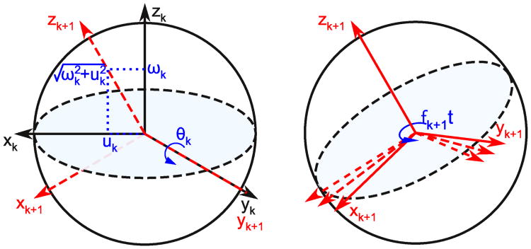
To generate (1) and (2), we propose RF fields that are constant along the x-axis uk(t) = uk(0) and modulated along the y-axis νk(t) = 2νk+1(t) cos(fk+1t)+ 2uk+1(t) sin(fk+1t). We will resolve this modulation such that (uk+1(t), νk+1(t)) is an arbitrary effective RF pulse applied in the subsequent frame. Notice that the Hamiltonian is time-invariant in the x-z plane. Now we tilt the reference frame such that the static part of the field is aligned with the z-axis (as in Figure 1). The required tilt angle is θk(ωk, uk) = atan2(uk, ωk) about the y-axis. Note that for each chemical shift value the frame is tilted differently; each spin now has its own set of coordinate axes. We adjust the Hamiltonian according to
Fig. 1.
In each tilted, rotating frame the Iz and Ix components of the Hamiltonian are time-invariant. We choose new axes for the Bloch sphere such that the new z-axis is aligned with the static part of the field, i.e. the vector sum of ωkẑ and ukx̂. This is achieved by tilting the frame about the y-axis. Next, we will construct a rotating frame about the new z-axis to displace the effective chemical shift by −fk+1. The effective chemical shift in the new frame is given by (2)
so that the time-invariant part of the field is along the z-axis, and the time-varying part of the field is along the y-axis. We now construct a rotating frame about the new z-axis (as in Figure 1), where the rotation rate is the fk+1. That is, the rotating frame precession rate is the same as the modulation frequency of νk(t). The Hamiltonian becomes
| (3) |
Finally, we decompose terms in the x-y plane into slowly and rapidly oscillating parts. The rapidly oscillating terms average to zero over relatively short timescales, so their net effect is small compared to the slower terms. For the purpose of developing a design algorithm, we neglect these fast terms. This is the rotating wave approximation (RWA) (Ernst et al 1987). However, since we make the RWA for terms that are kHz from resonance (it is most usually evoked for terms that MHz off resonance), we will demonstrate its validity for our pulses in detail in subsection 2.5 below. Under this approximation, we have
| (4) |
The Iz component is the effective chemical shift in frame k+1, so the original chemical shift bandwidth/band-structure is mapped to a new effective bandwidth/band-structure. (4) is equivalent to (1) and (2).
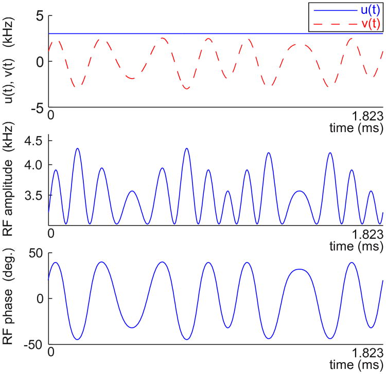
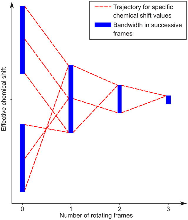
The design task is to choose the pulse amplitudes {uk} and modulation frequencies {fk} (these are also rotating frame precession rates) such that the recursion (2) transforms a large chemical shift bandwidth into a small effective bandwidth. Sections 2.2 and 2.3 show how to choose these free parameters. Figure 2 shows a typical pulse profile. Figure 3 is a schematic of the design process: each application of (2) further compresses the effective chemical shift range.
Fig. 2.
A pulse designed using three tilted, rotating frames. The Cartesian components (top) have a static x-component and a y-component comprising multiple modulations, according to (7). The equivalent amplitude (middle) and phase (bottom) functions are generated from the Cartesian functions u(t) and ν(t). The root-mean-square amplitude of the pulse is 3.5 kHz
Fig. 3.
Equation (2) can be used to effectively compress a large bandwidth. In this schematic, chemical shift values are updated using (2) three times. Although (2) applies to individual effective chemical shifts (dashed lines), we can choose pulse parameters so that the set of effective chemical shifts present in the sample becomes smaller with each new frame. Two distinct bands are overlaid, and then updated several more times to reduce bandwidth
2.2 Frame alignment and choice of modulation frequencies
We apply a series of frame changes, each characterized by a unitary matrix Uk+1,k(ωk, t) which transform the Hamiltonian and quantum state from the kth frame to the next (k+1) frame. These time-varying frame changes are defined differently for each chemical shift value. We repeat this several times, so that we can apply (2) sufficiently many times to reduce the effective bandwidth. Uk+1,k(ωk, t) comprises a tilt about the y-axis by θk(ωk, uk), followed by a rotation about the z-axis at rate fk+1:
The transform from the original frame to the kth rotating frame is
where the effective chemical shifts {ωk} are calculated from the original chemical shift ω and the pulse parameters by (2). Clearly,
Additionally, we will require that all rotation frequencies obey fjT = 2mjπ, where T is the pulse time and {mj} are integers. In this case,
| (5) |
which is a net tilt about the y-axis, regardless of the values of the effective chemical shifts in each frame {ω1, ω2,…,ωk}. This ensures that at the beginning and end of the pulse, the y-axis of each multi-tilted, multi-rotating frame is aligned with the y-axis in the original frame. However, during the pulse the frames are generally mis-aligned for different chemical shift values.
There are now two conditions on the choice of modulation frequencies: they occur in integer multiples (for frame alignment) and they decrease in magnitude sufficiently quickly with each new frame that terms suppressed under the RWA always oscillate faster than terms that are not suppressed. These can be jointly satisfied only if
| (6) |
2.3 Choice of pulse amplitudes
Each additional tilted, rotating frame is used to further manipulate the effective bandwidth. In order to construct each new frame it is necessary to include a further sinusoidal modulation to the pulse. Therefore, the complete pulse comprises nested modulations (Figure 2). The y-component of the pulse profile obeys the recursion
| (7) |
where {u1, u2,…, un}, νn, and {f1, f2,…, fn} are design parameters. Finally, we set νn constant and un = 0. The Hamiltonian in the nth frame is
If |ωn|≪|νn| then α=νnT is the flip angle about the y-axis.
Suppose we wish to use (2) to drive a large original bandwidth |ω0| ≤ C0 to a small final bandwidth |ωn| ≤ Cn ≪ C0. The appropriate pulse amplitudes {uk} to achieve this goal are given by a simple recursion. Notice from (2) that . If we choose fk to center the bandwidth at ωk=0, then
| (8) |
Equivalently,
| (9) |
| (10) |
where the recursion is fixed by choice of Cn (bandwidth in the nth frame) and frequencies {f1, f2, …, fn} obeying (6). Clearly, we ought to choose Cn ≪ |νn| to execute a uniform rotation (flip angle α = νnT) around the y-axis over the bandwidth C0 in the original frame of reference. For a chosen set of modulation frequencies obeying (6) and a desired effective bandwidth Cn, the pulse amplitudes {uk} and the working bandwidth in the original frame C0, are specified by (9) and (10). The pulse designer should choose the frequencies to achieve a satisfactory working bandwidth. Examples are f4, …, f1 ∝ 1,2,4,8 or 1,2,5,10, or f3, f2, f1 ∝ 1,3,7.
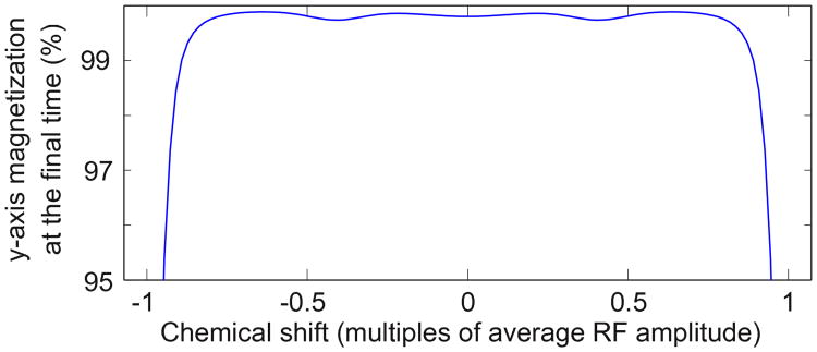
In the nth frame, we execute a uniform rotation about the y-axis. For a density matrix expressed in the final frame ρ(n)(0) = Iy, we have that for all time ρ(n)(t) = Iy; the nuclei are spin-locked to the y-axis. Since the y-axes in all tilted, rotating frames are aligned at time T, we also have that ρ(0) = ρ(T) = Iy in the original frame of reference (k = 0). That is, at the beginning and end of the pulse all spins are in phase along the y-axis (they are not in phase during the pulse). For example, Figure 4 shows via simulation how magnetization returns to in-phase along the y-axis after the pulse for a range of chemical shift values.
Fig. 4.
A pulse designed with three rotating frames is simulated for spin-locking of an ensemble of isolated spins-1/2. At the beginning of the simulation the magnetization is along the y-axis, and we measure the final magnetization along the y-axis, averaged over 20 values of the RF inhomogeneity, sampled uniformly between ±5% of the nominal power. We observe that magnetization is returned to near the y-axis at the end of the pulse over a large bandwidth. The pulse is repeated several times to achieve spin-locking over longer periods of time. The pulse time T is 6.38r/A, where r is the number of times the pulse is repeated (for this simulation r = 4) and A is the average RF amplitude. The pulse profile is displayed in Figure 2, its mixing performance is simulated in Figure 5, and it is tested experimentally in Figures 6 and 9
In a sense, we have used frame changes to simplify the calculation of the effective Hamiltonian (Haeberlen and Waugh 1968). As is the case for average Hamiltonian theory (Llor 1992; Haeberlen 1976), the Magnus expansion (Magnus 1954; Klarsfeld and Oteo 1989), and the Floquet expansion (Floquet 1883; Leskes et al 2010), we have constructed a time-invariant effective Hamiltonian which is valid at the endpoints of each time-period. However, our iterative scheme is not general; it is specific to the RF pulse form we suggest. The advantage is that the pulse design proceeds recursively and analytically. Each free parameter can be chosen in turn by consideration of (2) (and (11) for coupled spins), without using the full Magnus or Floquet machinery. Rather, we use some of the most fundamental and familiar NMR concepts (Cavanagh et al 2006; Ernst et al 1987) (choice of axes, rotating frames, the RWA, sinusoidally modulated fields) to construct a time-varying RF pulse under which the effective time-invariant Hamiltonian has the desired form.
2.4 Robustness to RF inhomogeneity
Although our pulse design method does not explicitly account for variations in RF inhomogeneity, we nonetheless observe insensitivity to RF power variations in computer simulations (as shown in Figure 4) and good performance in experiments for all pulses we have designed and tested. This can be understood by consideration of a slightly modi-fied version of (2)—even under RF inhomogeneity, we still see a similar systematic frame-by-frame reduction in effective chemical shift bandwidth.
In the presence of RF inhomogeneity all pulse amplitudes in our analysis should be scaled by σ, an inhomogeneity factor sampled from a neighborhood of unity, e.g. σ ∈ [0.9, 1.1]. In particular, (2) would be instead
which would change the calculated values of {ωk}. Since our algorithm is, by design, robust to variations in effective chemical shift in each frame, this change would not prevent adequate performance for σ ≈ 1. The recalculated ωk will typically remain within the design bandwidth |ωk| ≤ Ck. The exception is at the edges of the bandwidth in frame k−1, where the (recalculated) effective chemical shift ωk could fall outside of the design bandwidth Ck. Chemical shifts slightly outside of the design bandwidth are still reduced via subsequent frame changes; nonetheless, this effect is a source of error. RF inhomogeneity leads to larger than desired final-frame effective chemical shifts; however, simulations (e.g. Figure 4) and experiments confirm that the effect is small.
The spin-locking nth frame Hamiltonian is now H(n) = ωnIz + σνnIy. This will still achieve spin-locking provided the (recalculated) effective chemical shift remains small compared to |νn|.
2.5 The effect of neglected off-resonance terms
The derivation of our design method relied on the RWA to generate (4). Rapidly oscillating terms average to zero over relatively short timescales, and so their overall effect is smaller than the slower terms. However, these terms can have a non-negligible effect on the dynamics, and this can be captured by a time-invariant correction to the Hamiltonian called the Bloch-Siegert shift (Bloch and Siegert 1940). For the familiar transform from the laboratory frame to the frame rotating at the Larmor frequency, the correction is negligible and is safely ignored. However, for the kHz frequency terms we have suppressed the shift is not negligibly small for the first few frame changes. In this subsection we demonstrate how the Bloch-Siegert shifts for off-resonance terms change the effective chemical shifts in each frame. Our method is, by design, robust to differing chemical shift in successive frames, so these corrections do not ruin our pulse design method.
The Bloch-Siegert shift can be calculated using three frame changes (Sacolick et al 2010). A rotating frame transformation renders the far off-resonance term time-invariant, a tilt by a small angle combines the this time-invariant term with the chemical shift offset, and finally the rotating frame transformation is reversed. The net result is a correction to the chemical shift offset with magnitude B2/2(ω − 2f), where B is the amplitude and ω − 2f is the distance from resonance for a circularly polarized term with frequency 2f.
We expand (3) using (7) and find that the off-resonance terms are mostly cosines along the x-axis and sines along the y-axis (the exceptions are terms proportional to νn and with frequencies near ±2fk for the kth frame change. These are extremely low amplitude, highly oscillatory, and therefore neglected here). We rewrite (3) as
where the set of parameters {aj, fj} are the amplitudes and frequencies of far off-resonance terms. Note that these terms are distributed above and below resonance, which leads to some cancellation amongst Bloch-Siegert shifts with opposite signs.
We construct a rotating frame at the rate fm of one of the off-resonance terms, so that
We can combine the two time-invariant terms via a tilt about the y-axis by a small angle βm. This means that all the x-axis terms are also tilted into the x-z plane:
where c and s are shorthand for cosine and sine. For a small angle βm, highly oscillatory terms proportional to (cos(βm) − 1) or sin(βm) have very little effect on the dynamics, and so we can safely neglect the last two lines of the previous equation. Finally we reverse the rotating frame transformation to obtain
We obtain the Bloch-Seigert shift by noting the offset frequency is approximately . This can be shown by a Taylor expansion of the square root in the previous equation, with the parameter . The Hamiltonian no longer contains a circularly polarized term with frequency fm. This process can now be repeated for the other off-resonance terms still present in the Hamiltonian.
Crucially, the rotating frames used to derive all corrections have that T fm is an integer multiple of 2π, so these all align at stroboscopic times. However, to derive the corrections we used tilts about the y-axis by angles βm, and had static terms along the z and x axes. In other words, the Bloch-Seigert corrections are contained in the x-z plane. Recall that our design algorithm combines all time-invariant terms in the x-z plane and treats them as the effective chemical shift in the next frame. Since our method is robust to variations in chemical shift in successive frames, the Bloch-Siegert shifts do not invalidate (1); they merely reduce the precision with which (2) keeps track of the effective chemical shifts in each frame. As for the case of RF inhomogeneity, the relevant correction reduces the precision of (2), but does not threaten the overall architecture of our design method.
In simulations we find the responses to our RF pulses are well captured by (4) without any Bloch-Siegert corrections (see Figures 4 and, especially, 5), so we have elected to preserve the simplicity of our design method by neglecting these corrections during pulse design. Of course, our simulations employ the full dynamics; we evoke the RWA only to derive the pulse design algorithm.
2.6 Maintaining the J-coupling
The Hartmann-Hahn mixing condition says that cross-polarization will occur provided that the effective J-coupling between two spins is large relative to the separation in their effective chemical shift frequencies. We have shown that in the nth tilted, rotating frame the effective chemical shift bandwidth is small for an ensemble of isolated spins-1/2. We now consider isotropically coupled pairs of spins-1/2, and transform the coupling tensor into the nth frame so that the effective coupling can easily be calculated from the pulse parameters.
In the original frame of reference, the coupling Hamiltonian for spins I and S is
When we change frames, each spin's frame is tilted differently. Spin I is tilted by θ = atan2(u0, ωI), while spin S is tilted by φ = atan2(u0, ωS). The time-averaged coupling Hamiltonian in the first tilted, rotating frame is
The range of tilt angles is determined by the RF amplitude allowance for |u0| and the chemical shift bandwidth. This equation has previously been used for nutating frame spectroscopy (Grzesiek and Bax 1995). We now generalize this calculation for the case of a series of rotating frame constructions, since subsequent frame tilts and rotations further truncate the effective coupling strength. If the tilt angles for the kth change of frames are θk (for spin I) and φk (for spin S), then the components of the average coupling Hamiltonian evolve as
| (11) |
where c and s are shorthand for cosine and sine. The initial conditions are a0 = b0 = 2πJ. We retain only the average coupling after each frame change, and suppress the parts that oscillate at multiples of frequency fk. These terms average out during the pulse. In practical applications, J is tens of Hertz, while fk is kilohertz, so the suppressed terms are very weak and highly oscillatory, and therefore are negligible.
Two cases in particular are worth exploring: firstly, when ωI and ωS are equal. This is the main diagonal of a two dimensional spectrum. In this case, for all k, (ak + bk)/2 = 2πJ, so that Iy → Sy in time Tmix = 1/(2J). Secondly, when ωI = −ωS and the separation is large, so that θ1 = φ1 + π. This occurs in dual-band pulses (see Figure 8). In this case, a1 = −2πJ and b1 = 0; that is, an effective coupling is maintained that is orthogonal to the spin-locking axis. Since (ak + bk)/2 = −πJ, dual-band pulses will transfer polarization between a scalar-coupled pair in time Tmix = 1/(J).
Fig. 8.
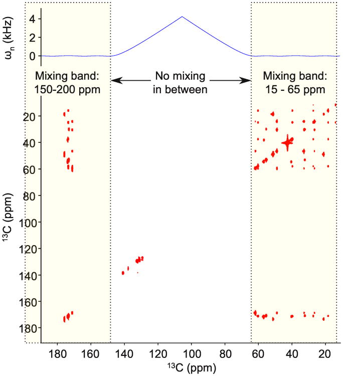
A dual-band mixing pulse is tested experimentally with the PIFHA peptide. We set the carrier at 105 ppm and the two bands fall over the aliphatic and carbonyl regions of the carbon spectrum. The solid line shows the effective chemical shift in the nth frame calculated using (2). The mixing time is 56 ms. The average RF amplitude is 3.75 kHz, while the bandwidth is 2 × 6.25 kHz with a 10.7 kHz gap. We see cross peaks between and within the carbonyl and aliphatic spectral regions
In general, we can approximate the cross-polarization during the mixing period by the average Hamiltonian in the nth frame. Let T be the pulse time, r be the number of times the pulse is repeated, and V(t) be the unitary solution to the Schrodinger equation for the coupled two spin system, expressed in the nth frame of reference. At times t = rT, the nth frame is tilted about the y-axis with respect to the original frame (see (5)). This tilt commutes with density matrices that are effectively spin-locked to the y-axis, which means V(t) is adequate for modeling in-phase cross-polarization. Then
| (12) |
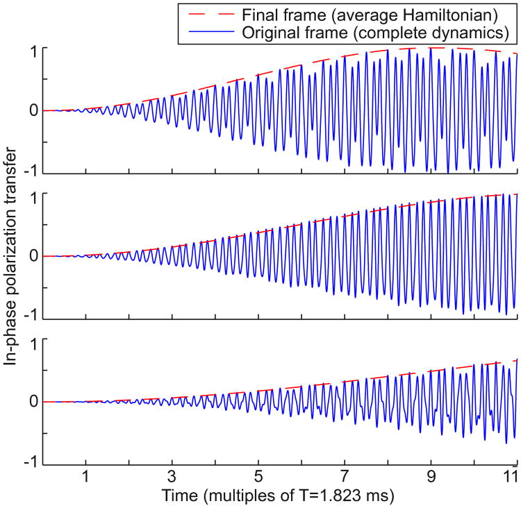
where an and bn are generated by (11), νn is the time-invariant effective pulse applied in the final frame, and the two ωn are generated by applying the recursion (2) to the initial chemical shifts ωI and ωS (by design, these ωn values are much smaller than νn). These constants can be calculated from the pulse parameters and chemical shifts much faster than a full simulation of the time-varying Hamiltonian in the original frame of reference. However, the y-axes for these frames align at times t = rT. For polarization transfer between coupled spins (which are spin-locked to the y-axis in the nth frame), we require that (an+bn)/2 is large enough to dominate the residual chemical shifts |ωn| ≤ Cn. In other words, we require that the Hartmann-Hahn mixing condition is satisfied for the average Hamiltonian in the final frame, for all desired pairs of chemical shift offsets. Figure 5 compares (12) to the complete dynamics in the original frame of reference, and shows that cross-polarization can be quite accurately predicted by the average Hamiltonian in the final tilted, rotating frame.
Fig. 5.
Homonuclear cross-polarization using the nth frame average Hamiltonian (12) is compared to the complete Schrödinger dynamics in the original frame, for various chemical shift offsets. JIS = 35 Hz, the initial density matrix is ρ(0) = Iy, and we plot the in-phase transfered magnetization 2tr(Syρ(t)). The average power is 3.5 kHz. Crucially, the magnetization is in-phase along the y-axis precisely at integer multiples of time T when the y-axes of all frames are aligned. Chemical shift offsets in the original frame of reference are ωI = 1 kHz and ωS = −1 kHz (upper), ωS = −2 kHz (middle), and ωS = −3 kHz (lower)
2.7 RF amplitude and pulse time
For each frame change, we can choose fk to at least halve the effective bandwidth, irrespective of the amplitude allowance |uk−1|. To see this, observe that (8) implies Ck+1 ≤ Ck/2. Therefore Ck ≥ 2n−kCn, so that the effective bandwidth Cn decays exponentially with the number of tilted, rotating frames. However, each frame change adds an extra modulation to (7), which increases the average amplitude of the RF pulse. The root-mean-square average amplitude A of the RF pulse can be calculated from (7):
| (13) |
We find that with 3 to 5 changes of frame, (9) and (10) yield pulses with bandwidth-to-RF amplitude ratios (C0/A) of 2 or higher. The J-coupling is largely maintained between any two spins sampled from the bandwidth. Pulse times T are on the order of milliseconds. Therefore, we can loop the pulse several times to get the appropriate mixing times for protein spectroscopy (order tens of milliseconds), cover the appropriate bandwidth (order kHz or tens of kHz), and obey average RF amplitude limits (order kHz).
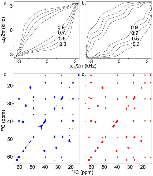
Standard mixing pulses have bandwidth-to-RF amplitude ratios of about 2 (Glaser and Quant 1996). For the same average RF amplitude we can have a larger mixing bandwidth using a pulse designed using tilted, rotating frames. For example, Figure 7 contains simulations and experiments that show larger bandwidth-to-RF amplitude ratios for a multi-frame mixing pulse than for a FLOPSY-16 sequence.
Fig. 7.
A mixing pulse designed with three tilted, rotating frames is compared to FLOPSY in simulation and experiment on the PIFHA peptide. The average RF power is 2.6 kHz. a. FLOPSY-16 simulation of in-phase transfer Iz → Sz as a function of offset frequencies. JIS = 26.5 Hz so that the FLOPSY-16 duration is 1/(2JIS). b. Multiframe simulation of in-phase transfer Iy → Sy. The pulse is repeated eight times to achieve approximately the same mixing time as FLOPSY-16. c. FLOPSY-16 is applied to a sample. It fails to resolve, or weakly resolves, various cross peaks near the edges of the spectrum. d. The multi-frame pulse resolves all cross peaks in the aliphatic spectral region. The average RF amplitude, carrier frequency, mixing time (37 ms), number of scans, and display settings are the same for the two spectra
In practice, at typical RF power levels for carbon channel TOCSY experiments, the use of more than 5 rotating frames will produce a pulse time of tens of milliseconds. This means it is difficult to match the desired mixing time, i.e. the pulse may be shorter than the required mixing time, but when repeated twice it may be longer than the required mixing time. Furthermore, with more than 5 rotating frames (11) will tend to show a small effective coupling between widely separated chemical shifts. That is, with too many frames it is difficult to maintain the J-coupling between all possible spin pairs in the bandwidth.
2.8 Multi-band mixing
When the chemical shift frequencies of interest fall into distinct, widely separated spectral regions we can save power by ignoring the empty parts of the spectrum and targeting the interesting frequency bands. For example, the carbon chemical shifts in protein samples fall into several distinct bands (Cavanagh et al 2006), so it is sufficient to transfer polarization between and within these bands; there is no need to satisfy the Hartmann-Hahn mixing condition in the unpopulated spectral regions. Dual-band mixing pulses have previously been designed by adding an extra modulation to Gaussian inversion pulses (Carlomagno et al 1996; Zuider-weg et al 1996) or to the WALTZ-16 sequence (Grzesiek and Bax 1995), or in solid state NMR by adding an extra modulation to a spin-lock field (Zhang et al 2012). In fact, (2) can also be used to effectively collapse and simplify a multi-band structure.
Suppose that in the kth frame there are two equally wide bands of interest. We can choose the frequency fk halfway between the midpoints of these bands, so that |ωk| ∈ [a, b], where b > a > 0. For dual-band structures in the original frame (k = 0), this means setting the carrier frequency for the pulse halfway between the bands. Next, set uk = 0 and fk+1 = (a + b)/2. Applying (2)
Then Ck+1 = (b − a)/2. In the k + 1 frame, there is a single band centered around ωk+1 = 0, with ωk+1 ≤ Ck+1. If this band is wide then we can construct further tilted, rotating frames to reduce it as in Figure 3. Alternatively, if this band contains more empty spectral regions, we can overlay two of these regions in the k + 2 frame, and so on. In this way, we can choose to have two active bands in the original frame, or four, or eight, and so on.
The bands can be moved arbitrarily far apart without using more RF amplitude or taking more time. To see this, observe that increasing fk+1 (to move the bands further apart) does not change the RF amplitude (13). The pulse time T depends on fnT = 2π and flip angle α = νnT. Neither of these constraints are changed by increasing fk+1 (for k + 1 ≠ n).
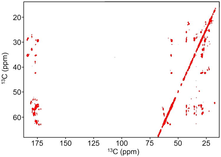
Figure 3 shows schematically how (2) can be used to collapse multi-band structures, so that in the final rotating frame the chemical shift bandwidth is small. Figure 8 presents a dual band pulse designed using four tilted, rotating frames, and Figure 10 tests the same pulse on a protein sample.
Fig. 10.
A 3.75 kHz multi-frame dual-band mixing pulse is used for dual-band TOCSY of BCL-XL. The pulse was designed using four rotating frames. The same pulse was used for Figure 8
3 Materials and methods
3.1 Synthesis of 13C 15N labeled HN-Pro-Ileu-Phe-His-Ala-Gly-CONH2
The peptide was synthesized on a Focus XC peptide synthesizer (Aapptec Louisville KY). H-Gly-Cll (Trt) resin (0.1 mmol, Novabiochem) with a loading capacity of 0.64 mmol / g in a 25 mL reaction vessel was allowed to swell for 40 minutes with alternate mechanical stirring and nitrogen bubbling. Labeled Fmoc protected amino acids (0.5 mmol, Sigma Aldrich) was activated for 10 minutes with HOBT/HBTU/DIPEA in 1:1 NMP/DMF solution. The activated amino acid solution was added to the resin and allowed to mix in the reaction vessel with alternate mechanical stirring and nitrogen bubbling for 90 minutes. Coupling and deprotection was monitored using the Kaiser test. The peptide was cleaved from the resin with 2% TFA in DCM for 60 minutes. The DCM was evaporated off with a stream of nitrogen gas. An oily, bright yellow compound remained. ACN : H2O (1:1) was added to this and lyophilized which resulted in a colorless solid. The protecting groups on the peptide as removed with a 10% TFA in DCM solution. The crude material was then purified by LC/MS (Agilent Technologies; Zorbax PrepHT 300SB-C18, 21.2 × 150 mm, 5 uM and Zorbax 300SB-C18, 2.12 × 150 mm, 5 uM), which resulted in a colorless fluffy powder in 28% overall yield. Note that the terminal Glycine is not 13C 15N labeled. For NMR experiments the peptide was at a concentration of 5mM in dmso-d6.
3.2 Recombinant expression and purification protein samples
Human carbonic anhydrase II (HCA II) was recombinantly expressed in E. coli and purified (Burton et al 2000). A uniformly 13C and 15N perdeuterated sample of HCA II at a concentration of 1mM (pH 7.4, 10 mM phosphate buffer) was used to generate Figure 9.
Fig. 9.
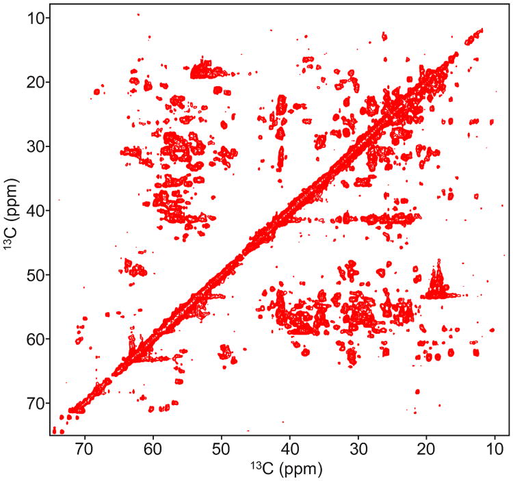
A 3.5 kHz multi-frame mixing pulse is used for TOCSY of human carbonic anhydrase II. The pulse was designed using three rotating frames. The same pulse was used for Figure 2 and Figure 6
A uniformly 13C, 15N, and 2H perdeuterated sample of B-cell lymphoma-extra large (BCL-XL) was recombinantly expressed and purified (Malia and Wagner 2007). The sample was used at a concentration of 1.02 mM. Figure 10 was produced using this sample.
3.3 TOCSY experiments
The data were collected on a 500 MHz Bruker spectrometer equipped with a cryogenic TXO probe. We performed carbon-carbon TOCSY experiments in the presence of proton and nitrogen decoupling during mixing and detection of the direct dimension, with a multi-frame pulse deployed for the homonuclear cross-polarization stage of the experiment. The shaped amplitude and phase profiles of the mixing pulse were finely discretized due to spectrometer software requirements. The experiments with the peptide PIFHA were done at 298 K, the experiment on the HCA protein was done at 310 K, and the experiment on the BCL-XL protein was done at 303 K.
4 Experimental results
We present experimental tests of three pulses designed by the multi-rotating frame method.
Our first example mixing pulse is displayed in Figure 2. The modulation frequencies are f1/(2π) = 3.840 kHz, f2/(2π) = 1.097 kHz, and f3/(2π) = 0.549 kHz. The pulse amplitudes are u0/(2π) =3.026 kHz, u1/(2π)= 0.946 kHz, u2/(2π) = 0.538 kHz, and ν3/(2π) = 0.137 kHz. The mixing time must be an integer multiple of T = 2π/ f3 = 1.823 ms for frame alignment. Note that for the case of three rotating frames (7) is explicitly
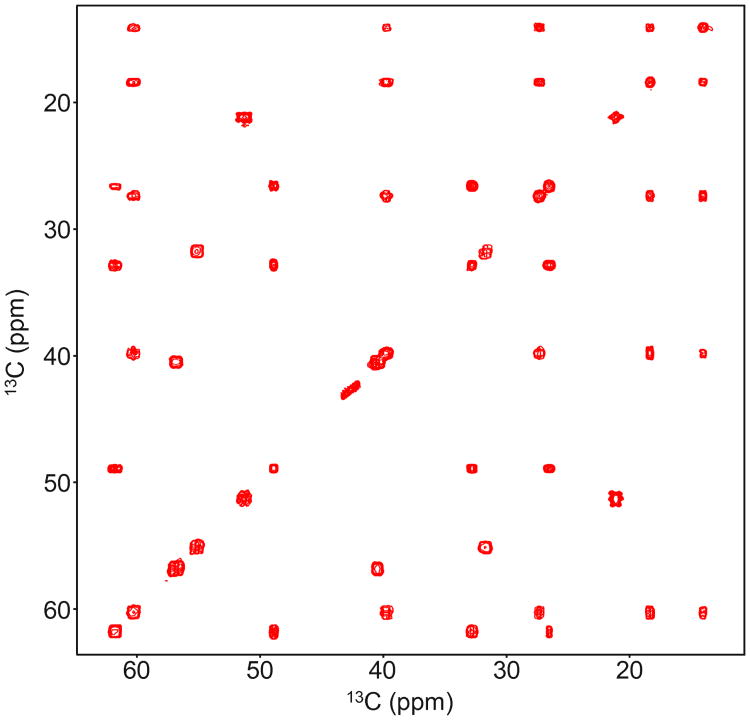
applied along the y-axis for t ∈ [0, T]. The x-component, u0, is time-invariant. This pulse was simulated for effective spin locking (Figure 4) and in-phase magnetization transfer (Figure 5). The average RF amplitude is 3.5 kHz and the mixing bandwidth is approximately 6.5 kHz. Figure 6 shows the performance of this pulse in a TOCSY experiment of the synthetic peptide. The mixing time is 16T ≈ 29 ms. All cross peaks are clearly resolved. Figure 9 shows the same pulse applied to a protein sample.
Fig. 6.
A pulse created with three rotating frames is tested in a TOCSY experiment on the synthetic peptide PIFHA uniformly labeled with 15N and 13C. The average RF amplitude is 3.5 kHz, and all cross peaks are clearly resolved over the 6.25 kHz bandwidth. The carrier frequency is 40 ppm and the mixing time is 16T ≈ 29 ms. The pulse amplitude and phase profiles are given in Figure 2
The second example pulse designed by multi-rotating frames is compared to the FLOPSY-16 sequence in Figure 7. The average RF amplitude is set to 2.6 kHz. This power level allows us to demonstrate the different bandwidths of FLOPSY and our pulse: FLOPSY fails to cover the aliphatic peaks in our sample, whereas the multi-frame pulse resolves all cross peaks in the same sample. We also show simulations of homonuclear cross-polarization between two isotropically coupled spins, demonstrating the larger bandwidth of the multi-frame pulse. The modulation frequencies are f1/(2π) = 2.943 kHz, f2/(2π) = 1.261 kHz, and f3/(2π) = 0.420 kHz. The mixing time must be an integer multiple of T = 2π/f3 = 2.379 ms. The pulse amplitudes are u0/(2π) = 1.956 kHz, u1/(2π) = 1.038 kHz, u2/(2π) = 0.391 kHz, and ν3/(2π) = 0.158 kHz.
Our third example pulse has two separate mixing bands, and was designed for TOCSY amongst Cα and carbonyl spins. The modulation frequencies are f1/(2π) = 8.547 kHz, f2/(2π) = 2.849 kHz, f3/(2π) = 1.425 kHz, and f4/(2π) = 0.356. The mixing time must be an integer multiple of T = 2.808 ms. We set u0 = 0 to bring about the dualband structure, as explained in the previous section. The other pulse amplitudes are u1/(2π) = 1.817 kHz, u2/(2π) = 1.2557 kHz, u3/(2π) = 0.3365 kHz and ν4/(2π) = 0.1246 kHz. The root-mean-square RF amplitude is 3.75 kHz. Figure 8 shows a TOCSY experiment using this pulse with mixing time 20T ≈ 56 ms. We see well-resolved cross peaks between the aliphatic and carbonyl regions. The aromatics (125-140 ppm) are not in the active bands for this pulse, so they do not mix with the other spins. Figure 10 shows the same pulse applied to a protein sample.
Finally, note that these pulses can be scaled to other chemical shift bandwidths (including other field strengths). The bandwidth, amplitudes {uk} and modulation frequencies {fk} are all scaled by the same constant, and the pulse time T is scaled by the inverse of that constant. At the new power level, the pulse can be repeated any number of times to achieve the desired mixing time. Therefore, the trade-offs amongst mixing bandwidth, mixing time, and RF power can be negotiated by the spectroscopist for each application.
5 Conclusion
Our pulse design method provides an analytical solution to the problem of large bandwidths in correlation NMR, relying on familiar kinds of Hamiltonian transforms (tilted axes, rotating frames, and rotating wave approximations), and does not require numerical searches/optimizations. Equation (2) allows chemical shift bandwidths to be precisely manipulated in a variety of ways, which we have explored here. With some care, a pulse can be engineered so that the coupling tensor dominates the effective Hamiltonian—a highly desirable situation in HOHAHA mixing experiments. These mixing pulses have been successfully applied in carbon-carbon TOCSY experiments over large bandwidths and at low RF power.
Future work includes considering the effects of relaxation, exploring the utility of these pulses in high field spectroscopy, and resolving weak (i.e. 2-5 Hz) J-couplings present in protein samples.
Acknowledgments
This work is funded by Agilent Foundation, NIH grants GM047467, GM075879 and P41-EB002026. T.Y.Y. thanks the National Science Council in Taiwan (NSC98-2917-I-564-157) for partial financial support. H.A. thanks NIH grant NIDDK-K01-DK085198 for financial support.
Contributor Information
Paul Coote, Email: pcoote@fas.harvard.edu, School of Engineering and Applied Sciences, Harvard University, Cambridge MA 02318, USA.
Haribabu Arthanari, Email: hari@hms.harvard.edu, Department of Biological Chemistry and Molecular Pharmacology, Harvard Medical School, Boston MA 02215, USA.
Tsyr-Yan Yu, Department of Biological Chemistry and Molecular Pharmacology, Harvard Medical School, Boston MA 02215, USA.
Amarnath Natarajan, Eppley Institute for Cancer Research, University of Nebraska Medical, Center, Omaha NE 68198, USA.
Gerhard Wagner, Department of Biological Chemistry and Molecular Pharmacology, Harvard Medical School, Boston MA 02215, USA.
Navin Khaneja, School of Engineering and Applied Sciences, Harvard University, Cambridge MA 02318, USA.
References
- Bennett AE, Gross JD, Wagner G. Broadband 13C–13C adiabatic mixing in solution optimized for high fields. J Magn Reson. 2003;165(1):59–79. doi: 10.1016/s1090-7807(03)00244-1. [DOI] [PubMed] [Google Scholar]
- Bloch F, Siegert A. Magnetic resonance for nonrotating fields. Phys Rev. 1940;57:522–527. [Google Scholar]
- Braunschweiler L, Ernst R. Coherence transfer by isotropic mixing: Application to proton correlation spectroscopy. J Magn Reson. 1983;53:521–528. [Google Scholar]
- Burton R, Hunt J, Fierke C, Oas T. Novel disulfide engineering in human carbonic anhydrase ii using the pairwise side-chain geometry database. Protein Sci. 2000;9:776–785. doi: 10.1110/ps.9.4.776. [DOI] [PMC free article] [PubMed] [Google Scholar]
- Carlomagno T, Maurer M, Sattler M, Schwendinger MG, Glaser SJ, Griesinger C. PLUSH TACSY: Homonuclear planar TACSY with two-band selective shaped pulses applied to Cα, C′ transfer and Cβ, Caromatic correlations. J Biomol NMR. 1996;8:161–170. doi: 10.1007/BF00211162. [DOI] [PubMed] [Google Scholar]
- Cavanagh J, Fairbrother WJ, Palmer AG, Skelton NJ, Rance M. Protein NMR Spectroscopy: Principles and Practice. 2nd. Academic Press; San Diego: 2006. [Google Scholar]
- Ernst RR, Bodenhausen G, Wokaun A. Principles of Nuclear Magnetic Resonance in one and two dimensions. Clerendon Press; Oxford: 1987. [Google Scholar]
- Floquet G. Sur les equations differentielles lineaires a coefficients periodiques. Annales de l'Ecole Normale Superieure. 1883;12:47–88. [Google Scholar]
- Glaser SJ, Quant JJ. Homonuclear and heteronuclear Hartmann-Hahn transfer in isotropic liquids. Advances in magnetic and optical resonance. 1996;19:59–252. [Google Scholar]
- Grzesiek S, Bax A. Audio-frequency NMR in a nutating frame. application to the assignment of phenylalanine residues in isotopically enriched proteins. J Am Chem Soc. 1995;117(24):6527–6531. [Google Scholar]
- Haeberlen U. High resolution NMR in solids: selective averaging. Academic Press; New York: 1976. [Google Scholar]
- Haeberlen U, Waugh JS. Coherent averaging effects in magnetic resonance. Phys Rev. 1968;175:453–467. [Google Scholar]
- Hartmann SR, Hahn EL. Nuclear double resonance in the rotating frame. Phys Rev. 1962;128:2042–2053. [Google Scholar]
- Hedges L, Hoult D. The techniques of rotating frame selective excitation and some experimental results. J Magn Reson. 1988;79(3):391–403. [Google Scholar]
- Hoult D. NMR imaging, rotating frame selective pulses. J Magn Reson. 1980;38(2):369–374. [Google Scholar]
- Kadkhodaie M, Rivas O, Tan M, Mohebbi A, Shaka A. Broadband homonuclear cross polarization using flip-flop spectroscopy. J Magn Reson. 1991;91(2):437–443. [Google Scholar]
- Klarsfeld S, Oteo JA. Recursive generation of higher-order terms in the Magnus expansion. Phys Rev A. 1989;39:3270–3273. doi: 10.1103/physreva.39.3270. [DOI] [PubMed] [Google Scholar]
- Leskes M, Madhu PK, Vega S. Floquet theory in solid-state nuclear magnetic resonance. Prog Nucl Magn Reson Spectrosc. 2010;57(4):345–380. doi: 10.1016/j.pnmrs.2010.06.002. [DOI] [PubMed] [Google Scholar]
- Llor A. Equivalence between dynamical averaging methods of the Schrödinger equation: average Hamiltonian, secular averaging, and Van Vleck transformation. Chem Phys Lett. 1992;199(3–4):383–390. [Google Scholar]
- Magnus W. On the exponential solution of differential equations for a linear operator. Commun Pur Appl Math. 1954;7(4):649–673. [Google Scholar]
- Malia T, Wagner G. NMR structural investigation of the mitochondrial outer membrane protein VDAC and its interaction with antiapoptotic Bcl-xL. Biochemistry. 2007;46(2):514–525. doi: 10.1021/bi061577h. [DOI] [PMC free article] [PubMed] [Google Scholar]
- Müller L, Ernst R. Coherence transfer in the rotating frame. Mol Phys. 1979;38(3):963–992. [Google Scholar]
- Rucker S, Shaka A. Broadband homonuclear cross polarization in 2D N.M.R. using DIPSI-2. Mol Phys. 1989;68(2):509–517. [Google Scholar]
- Sacolick LI, Wiesinger F, Hancu I, Vogel MW. B1 mapping by Bloch-Siegert shift. Magn Reson Med. 2010;63(5):1315–1322. doi: 10.1002/mrm.22357. [DOI] [PMC free article] [PubMed] [Google Scholar]
- Zhang Z, Miao Y, Liu X, Yang J, Li C, Deng F, Fu R. Dual-band selective double cross polarization for heteronuclear polarization transfer between dilute spins in solid-state MAS NMR. J Magn Reson. 2012;217(0):92–99. doi: 10.1016/j.jmr.2012.02.020. [DOI] [PMC free article] [PubMed] [Google Scholar]
- Zuiderweg ER, Zeng L, Brutscher B, Morshauser RC. Band-selective hetero- and homonuclear cross-polarization using trains of shaped pulses. J Biomol NMR. 1996;8:147–160. doi: 10.1007/BF00211161. [DOI] [PubMed] [Google Scholar]


