

Abstract
This work presents an array of microfluidic chambers for on-chip culturing of microorganisms in static and continuous shear-free operation modes. The unique design comprises an in-situ polymerized hydrogel that forms gas and reagent permeable culture wells in a glass chip. Utilizing a hydrophilic substrate increases usability by autonomous capillary priming. The thin gel barrier enables efficient oxygen supply and facilitates on-chip analysis by chemical access through the gel without introducing a disturbing flow to the culture. Trapping the suspended microorganisms inside a gel well allows for a much simpler fabrication than in conventional trapping devices as the minimal feature size does not depend on cell size. Nutrients and drugs are provided on-chip in the gel for a self-contained and user-friendly handling. Rapid antibiotic testing in static cultures with strains of Enterococcus faecalis and Escherichia coli is presented. Cell seeding and diffusive medium supply is provided by phaseguide technology, enabling simple operation of continuous culturing with a great flexibility. Cells of Saccharomyces cerevisiae are utilized as a model to demonstrate continuous on-chip culturing.
I. INTRODUCTION
Cultivating different cell types on microfluidic devices outperforms conventional culture methods in many ways. A major advantage is that the systems in the microscale can provide tightly controlled culture conditions, mimicking the in vivo environment of cells.1 The possibilities of coculturing multiple cell types while studying their interactions have led to the emerging subfield of organs on chip.2 In addition, microfabrication technologies enable cointegration of online analysis and manipulation concepts, such as micro electrodes and optoelectronic devices.3–6 Key issues in microfluidic cell cultures are the need for defined cell seeding, supply of nutrients and gases, as well as keeping the cells in place. Adherently grown cells are either attached to the bottom surface in 2-dimensional cultures or immobilized in 3-dimensional hydrogel structures.7–12 Cells that are growing in suspension usually are trapped by physical barriers, while the culture chamber is perfused with fresh medium.4,13,14 The shear stress induced by the constant fluid flow can have adverse effects on sensitive cells. In addition, small species, such as microorganisms with diameters down to 0.5 μm are difficult to trap. Devices for shear-free cultures make use of dead-end growing chambers with diffusive medium supply from a microfluidic channel. Seeding strategies, including injection through the chip cover,15 high pressure,16 or application of a vacuum,17,18 can be complex, while harvesting of cells after an experiment is hardly possible.
The majority of microfluidic cell culturing chips is fabricated in PDMS because of its inherent oxygen permeability.10–12,19–29 Some of them report on partial 3D cell culture patterning by arrays of posts,10–12 requiring delicate injection pressure control10 and, therefore, preventing wide spread application. At the same time, PDMS has several other disadvantages. Due to its hydrophobic nature, difficulties with priming, trapped air bubbles, and adsorption of proteins and dyes can arise. Furthermore, unstable surface properties and leaching of uncrosslinked oligomers have been reported.26–28 A variety of surface modification techniques have been developed to overcome those issues but they complicate fabrication and again reduce oxygen permeability.30 Other device concepts utilize polymeric membranes in hybrid fabricated devices for nutrient7,31,32 and oxygen supply.33
Recently, we have established a method for the maskless microstructuring of hydrogels in a microfluidic chamber for batch mixing in biochemical analysis.34 Capillary pressure barriers, so called phaseguides,35 have been utilized for in situ gel polymerization in a single step by capillary filling. In this contribution, we adopt the hydrogel structuring to fabricate micro culturing chambers in microfluidic chips enabling complete feeding control (gases and liquids) and on-chip analysis. Trapping suspended microorganisms (or cells) inside a closed hydrogel micro chamber yields many advantages in operation: (i) Leaving cells in suspension while nutrients, antibiotics, and indicator dyes are provided in the gel do not require any sample treatment and offer the potential for self contained and customized bacterial testing. (ii) Autonomous priming by the hydrophilic nature of the chip does not require external pressure and pumping, an essential benefit to gain acceptance in clinical use. (iii) During cell growth, oxygen is allowed to diffuse from the air-filled part of the chip through the gel to the micro chambers where the cells are seeded, yielding simple control over normoxia or hypoxia. (iv) Capturing the suspended growing microorganisms in a permeable gel chamber for subsequent diffusive staining allows for a much simpler fabrication technology because the minimum feature size is not governed by cell size as in conventional trapping devices (e.g., in PDMS). The open space enables safe and simple in-situ drug delivery by reducing operation to only one pipetting step. Only small batches of reagents and short incubation times (by short diffusion lengths) are required, while no external pressure is disturbing the culture (e.g., disrupting cellular chains by introduced flow). (v) The mechanical guiding structures inherently offer the possibility for simple cell seeding and medium supply in continuous cultures by utilizing the difference of two-phase and laminar flow.36
Antibiotic resistances of pathogenic bacteria have become a major health care problem, threatening the achievements of modern medicine.37 Cultivation of bacteria on agar plates has been the golden standard for bacterial analysis but the method is laborious and time consuming. Chen et al. have shown that the high ratio of (oxygen permeable) surface to volume in microfluidic channels facilitates bacterial growth.29 Several rapid, microfluidic methods for antibiotic testing have been proposed, including easy handling devices with colorimetric readout,18,38 analysis of dielectrophoretic behavior,39 polymerase chain reaction,40 and continuous flow chips with immobilized samples.16,41–44
As recently stated by Whitesides45 and Chin et al.,46 a more general acceptance of microfluidic devices requires simple methodology and handling as well as alternative fabrication methods. Sacrificing oxygen permeability of PDMS-based devices for advantageous handling, priming, and fabrication requires an alternative solution for oxygenation. With the hydrogel oxygenation concept and the extra benefits of on-chip reagent storage and diffusive in-situ analysis of microorganisms in suspension the presented device adds significant value to microbiological analysis.
II. DEVICE FABRICATION AND OPERATION PRINCIPLE
The microfluidic devices are fabricated by hot roll lamination, enabling fast, parallel, and cost efficient fabrication. A schematic of the fabrication workflow is provided in the supplementary material, Fig. S1.54 In a first step, a layer of 100 μm dry film photoresist (Ordyl SY300, Elga Europe) is laminated on a glass slides and photolithographically structured to form the chambers and phaseguide pressure barriers. Fluidic access holes are powder-blasted (Easyblast, Bego) through a second glass slide, masked with a reusable photofilm (APM I-XE, Harke Imaging). Afterwards, a 50 μm dry resist layer is structured on the slide to form the open space above the guiding structures (Fig. 1(b)). The two glass slides are bonded by hot roll lamination. Plug-in connectors for Teflon tubes are made of PDMS, punched through with a needle and bonded over the inlet holes by oxygen plasma treatment.
FIG. 1.

The function of the device is illustrated in Fig. 1. A single chip consists of three functional regions, defined by Laplace pressure barriers (phaseguides) to guide liquid filling. A hydrogel is injected into the chip to define the growth chambers and allow gas diffusion from the outer part of the chip (Fig. 1(a)). The schematic cross section in Fig. 1(b) illustrates the principle of the phaseguide structures of 100 μm height and 40 μm width. An advancing liquid is induced to move along the guiding strips by the sudden capillary pressure change at the structures.
Diffusion time of a chemical species scales with the diffusion distance squared. In order to maximize oxygen influx and reduce diffusion time in subsequent cell staining, the distance through the gel to the culture should be minimized. This design input leads to the narrow finger structure, surrounded by a thin gel rim. A minimum width is given by practical aspects, including the maximum resolution and aspect ratio of dry film laminate, robustness of the guiding effect, and minimum liquid amounts for convenient pipetting. Previously, we have determined a value of 60% guiding structure height for robust on-chip patterning of complex gel networks.34 The interdependence of design parameters with their limits is illustrated in supplementary Fig. S2.54
Four culture chambers are designed in a symmetric shape with inlet holes in the center of the closed gel structure. The chambers are 250 μm wide, surrounded by another 250 μm of gel. With this design, the device contains about 1.6 μl hydrogel and sample, respectively.
For static cell cultures, the sample is injected into the central region 1 (Fig. 1(c)) after a chip is prepared with the gel. For in-situ analysis or chemical stimulus after incubation, a reagent is injected in the outer section 3 (Fig. 1(d), Multimedia view) and allowed to diffuse through the gel into the culture. In a continuous experiment, at first the sample fills the empty chamber along the guiding structures. Once the chamber is full, the liquid flows in a laminar regime, indicated by the red streamlines in Fig. 1(e) with negligible flow in the finger structures. This concept allows for cell seeding and medium supply via the same inlet without any additional operation steps (Multimedia view, Fig. 1(e)).
III. CHEMICALS AND EXPERIMENTS
Unless otherwise stated chemicals have been ordered from Carl Roth (Germany). The hydrogel is prepared of deionized water with 0.4% low melt agarose. In a standard procedure, the gel is autoclaved and cooled down to at which it is kept until injection into the chips. In order to cure the gel, the chips are cooled to .
For the glucose assay, L+ glucose is added to the gel precursor to give 250 mM. The sample, injected into the chip prepared with the glucose gel well, consists of glucose oxidase (Sigma Aldrich), horseradish peroxidase and potassium iodide (50 mM).
For bacterial testing, the gel is prepared with 20 mg/ml lysogenic broth (LB). Gram negative Escherichia coli (HB 101), Bacillus amyloliquefaciens (FZB42), and gram positive Enterococcus faecalis (DSM 16440) are cultivated on LB agar plates. Samples are prepared by diluting a colony in 10 mM phosphate buffered saline (PBS). For enumeration, serial dilutions are plated according to the drop based method.47
Stock solutions of ampicillin and gentamicin antibiotics are prepared in concentrations of , and 50 μg/ml for minimal inhibitory concentration experiments. Aliquotes are added to vials of 1 ml gel at to give the final antibiotic concentrations in a range from 0 to 128 μg/l. About 1.8 μl of gel are injected into each chip, the whole device is sealed with tape and stored at . Bacterial samples are injected into the chips with different antibiotic concentrations and subsequently incubated at in normal air for 3 h. After incubation, the cell permeable nucleic acid stain Syto-9 (Invitrogen) and gram positive specific hexidium iodide (Invitrogen) in DI water are added to the outer part of the chip and incubated for 15 min. Images are taken with a fluorescence microscope (Ex 470/30, Dm 495, Em 530 LP) with a mounted Nikon D5100 camera. Image analysis is performed in Image J to quantify bacterial growth (also see supplementary material54).
For colorimetric readout of bacterial growth 20 mg/ml lactose (Sigma Aldrich) and 2 mg/ml bromcresol purple are added to the gel precursor.
For the demonstration of enzyme assays, a fluorescent substrate (DQ Gelatin, Invitrogen) is used to determine the presence of bacterial gelatinase. For analysis the substrate (100 μg∕ml in Tris HCl buffer) is injected in chip region 3 after bacterial growth and incubated. Readings are performed after 15 min.
Saccharomyces cerevisiae has been obtained as a fresh package (Hagold) and directly suspended in PBS prior to the experiments. Continuous flow of 50 mg/ml YPD medium is provided by a syringe pump at 1 μl/min. Cells are cultured at room temperature, followed by time lapse photography on a microscope. Fluorescent live/dead staining is performed at the end of the experiment by adding 10 μM propidium iodide and 20 μM Syto 9.
IV. RESULTS AND DISCUSSION
Previously utilized photoinitiated hydrogels34 have been evaluated for use in this study. Polyethyleneglycol diacrylate, polyethyleneglycol dimethacrylate, and hyaluron acid vinyl ester48 have been investigated. Due to oxygen inhibition of the radical polymerization in the small structures, complete polymerization is only possible in a nitrogen environment, complicating the gel structuring. On the other hand, incomplete polymerized gels have shown to be a major reason for decreased biocompatibility as acrylate monomers are toxic to bacteria, resulting in reduced growth. While sufficiently cured gels showed good biocompatibility, these gels pose another major drawback by activating the fluorescent DNA dyes, making in-situ staining impossible (supplementary Fig. S3).54 Therefore, use of low melt agarose gels is an advantageous alternative as the gelling temperature allows handling with pipettes and chips at room temperature. Gels are prepared in analogy to conventional petri dishes with the gel chamber fabrication in only one pipetting step with subsequent cooling. The fabricated device shows excellent autonomous priming and robust guiding. Because of the thin finger structure, diffusion of a subsequently added drug is completed within few minutes (Multimedia view, Fig. 1(d)).
A. Oxygen supply
The chosen chip dimensions are governed by the trade-off between diffusion time and reliable filling. Oxygen diffusion from the empty part of a growth chip towards the cell culture has been calculated in a finite element simulation in Comsol Multiphysics 4.4 (Fig. 2(a)). With a diffusion coefficient of molecular oxygen in agar49 of , the concentration in the culture chamber is over 90% of that in the surrounding air within 2 min. An oxygen dependent glucose oxidase enzyme reaction has been used to visualize the oxygen influx through the gel (Fig. 2(b)). According to the following equation,50 glucose oxidase catalyzes the oxidation of glucose to hydrogen peroxide. Further, horseradish peroxidase catalyzes the reaction of hydrogen peroxide with potassium iodide to brown iodine
The devices are prepared with a glucose containing gel and the enzyme mix is introduced into the gel well. While in device C of Fig. 2(b), the region 3 remains empty, it is filled up in device D to remove ambient oxygen. As seen from the color difference in both devices, there is no reaction taking place in the finger structures of device D due to the absence of ambient oxygen. To show the influence of ambient oxygen on a bacterial culture, we have cultured aerobic, Gram positive B. amyloliquefaciens in two chambers in an analogue configuration. The comparison of bacterial growth after 10 h in an aerobic and anaerobic chamber is shown in Fig. 3. For the anaerobic growth condition, the chip region 3 in Fig. 3(a) is filled with culture medium. At the end, the medium is removed and both cultures are stained. This experiment confirms the simple and effective possibility to control aerobic and anaerobic growth conditions.
FIG. 2.

Illustration of oxygen supply. (a) Finite element simulation (Comsol Multiphysics 4.4) of oxygen diffusion through the gel. Within 2 min the oxygen concentration in the center is 92% of the concentration in air. (b) Visualization of oxygen influx through the gel by a glucose assay. In the left chip (C) the outer part is left empty to allow ambient oxygen to diffuse into the gel, while in right chip (D) it is also filled with the glucose gel. The absence of ambient oxygen in D inhibits the enzymatic color reaction.
FIG. 3.

Cultivation of aerobic growing gram positive B. amyloliquefaciens (orange staining). (a) Ambient oxygen is removed from device by filling region 3 with culture medium. (b) Oxygen is allowed to diffuse to the culture from the open space, enhancing bacterial growth.
B. Bacterial analysis
The simplest way to verify bacterial growth in a microfluidic chip is a colorimetric color change. Lactose fermenting bacteria, such as E. coli, produce an acid which induces a color change of a present pH indicator dye. A yellow color shift of bromophenol purple by a growing E. coli culture is shown in Fig. 4. However, a major disadvantage of the colorimetric readout is the dependence on the initial bacteria concentration, which results in a time dependence to grow a large enough colony that induces the color reaction. As a consequence, colorimetric devices are usually incubated over night to get a definite answer.18,38 For this reason, all further experiments have been done with in-situ fluorescent staining of bacterial samples.
FIG. 4.

Colorimetric assay of lactose fermenting bacteria. Serial dilutions of E. coli are incubated to show the impact of the initial concentration on the assay. Image was taken after 5 h incubation time. Initial sample concentrations: (H) 2.5 × 10⁷ Colony forming units (CFU) per ml. (I) 2.5 × 10⁶ CFU/ml. (J) 2.5 × 10⁵ CFU/ml. Only for the highest concentration, a definite prove of growth is present.
Microfluidic devices are well suited for fluorescent readout because the low channel height minimizes common medium autofluorescence and fits to the focus depth of a microscope. In addition, the structure of the presented chips allows for convenient in-situ staining after an experiment. Differential staining with Syto 9 and hexidium iodide not only yields the number of bacteria and their phenotype but also shows the Gram type in mixed cultures, altogether valuable information for analysis of clinical samples. Fig. 5(a) illustrates the simultaneous cultivation of Gram positive E. faecalis, which appear as orange cocci and Gram negative E. coli as green rods. In addition to the direct staining methods, enzymatic assays for bacteria identification can be performed in the chip. A bacterial gelatinase test is presented in Fig. 5(b). In contrast to E. coli, B. amyloliquefaciens cultures produce gelatinase that cleaves the injected substrate to yield high fluorescence. In clinical application, a gelatinase test is used to differentiate pathogenic S. aureus from nonpathogenic S. epidermidis and can take up to several days.51
FIG. 5.

Bacterial analysis. (a) Simultaneous growth of gram positive E. faecalis (orange) and gram negative E. coli (green). Staining with cell permeable Syto 9 and gram positive specific hexidium iodide. In the inset, the different phenotypes (cocci and rods) are well visible. (b) Proof of enzyme expression in a bacterial culture. In contrast to a control chip without bacteria and an E. coli culture B. amyloliquefaciens express gelatinase that can be detected by the fluorescent substrate within minutes.
As a reference for antibiotic susceptibility experiments, the used bacteria strains have been tested by the standardized disk diffusion method52 (available as supplementary material54). E coli has shown to be resistant against Ampicillin with a minimal inhibitory concentration (MIC) while susceptible to Gentamicin with a MIC . On the other hand E. faecalis is susceptible to Ampicillin with a MIC of and resistant to Gentamicin, as to all aminoglycosides.52
For antibiotic susceptibility tests, bacteria samples are introduced in 7 cultivation chambers that are prepared with antibiotic concentrations from 0 to . A control value of injected bacteria is recorded before incubation. Results of the experiments are summarized in Fig. 6. Comparing efficacy of antibiotics for each strain reveals that the rapid microfluidic method robustly determines susceptibility with MIC concentrations in accordance with the standard reference methods. As seen from the inset in Fig. 6(a) E coli growth is not inhibited at low Ampicillin concentrations but rather the bacteria grow in long chains. This chain formation has been associated with defense mechanisms against antibiotics, limiting their bactericidal effects.53 The fast and dramatic response to culture conditions in the microenvironment is remarkable.
FIG. 6.

Antibiotic testing of bacterial samples, incubated with varying concentrations of antibiotics. Bars represent mean growth values of 4 culture wells. Reference values are recorded before incubation. (a) E. coli have shown to be resistant against Ampicillin. The inset shows formation of long chains as a defense mechanism, limiting antibiotic efficiency. (b) Gentamicin effectively inhibits E. coli growth at all concentrations . (c) Inhibition of E. faecalis growth by Ampicillin . (d) E. faecalis resistance against Gentamicin at all concentrations.
In contrast to previously presented colorimetric assay methods,18,38 fluorescent analysis does not depend on initial concentration and incubation time (see also Fig. 4). While other bacterial testing methods require elaborate protocols for bacteria immobilization and external pumping16,41–44 the presented results suggest that the on-chip fluorescent gram staining, phenotyping, and enzyme assays add very interesting information and could be used for many bacterial analyses. In this respect, the possibility for precedent nutrient storage, as well as safe and simple drug application are essential technologies to reduce end-user work flow and gain acceptance of microfluidic technologies.
C. Continuous culturing
In addition to static cultures, the same device can be used for long-term culturing of suspended cells with continuous supply of fresh medium. The continuous configuration has been tested by culturing S. cerevisiae. A tube with continuous medium supply by a syringe pump is attached to the inlet. A small number of cells are seeded into the device (Fig. 7(a)) with the first few microliters, filling the chip. Once a laminar flow is established, fresh medium flows by the finger structures, supplying the cells by diffusion, as shown in Fig. 1(e). Without any additional steps, the cells are seeded and supplied with medium via the same inlet.
FIG. 7.
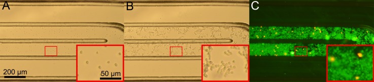
Continuous culturing of S. cerevisiae cells. (a) Seeding of a small number of cells into the chip. (b) The culture 10 h after experiment start. (c) High cell concentration after 20 h of cultivation with a high viability rate as indicated by fluorescent live/dead staining.
By the constant supply of fresh medium and removal of produced gas, the cells can grow to a very high concentration (Fig. 7(c)). After the experiment, viability has been verified in-situ by fluorescent live/dead staining. Only a low number of dead cells, which are stained by propidium iodide are seen in Fig. 7(c), revealing remarkably high viability. The possibility to expose the culture to chemicals without disrupting the continuous experiment yields many possibilities for drug testing experiments.
V. CONCLUSIONS
Microfluidic cell culturing techniques have made a tremendous progress in the recent years and led to a entirely new field of research. With the present design, we overcome a number of critical issues in the culturing of suspended cells, including autonomous priming, sample preparation, capturing microorganisms—fabrication resolution, in-situ drug delivery, nutrients supply, and oxygen control.
The in-situ polymerized hydrogel adds an enormous degree of freedom to fabrication and handling of on-chip cell cultures. For further analysis, enzyme assays can be run on the culturing device, just by one additional pipetting step. Injected culture medium agar can be prepared by microbiologists just as conventional petri dishes with various nutrients and drugs. Devices that are prepared in advance constitute a sample-in/answer-out system for the end user. With fourteen culture chambers on a convenient microscope format, parallel testing with a minimum of samples and reagents can be performed. Phaseguide assisted seeding and subsequent diffusive medium supply, enables shear-free cell cultures with the least possible complexity.
ACKNOWLEDGMENTS
This work has been supported by ACMIT—Austrian Center for Medical Innovation and Technology, which is funded within the scope of the COMET—Competence Centers for Excellent Technologies program of the Austrian Government.
References
- 1.Yeon J. and Park J., Biochip J. 1, 17 (2007); available at http://nanobio.kaist.ac.kr/papers/biochipj_1_17_2007.pdf. [Google Scholar]
- 2.van de Stolpe A. and den Toonder J., Lab Chip 13, 3449 (2013). 10.1039/c3lc50248a [DOI] [PubMed] [Google Scholar]
- 3.Charwat V., Purtscher M., Tedde S. F., Hayden O., and Ertl P., Lab Chip 13, 785 (2013). 10.1039/c2lc40965h [DOI] [PubMed] [Google Scholar]
- 4.Nevill J. T., Cooper R., Dueck M., Breslauer D. N., and Lee L. P., Lab Chip 7, 1689 (2007). 10.1039/b711874k [DOI] [PubMed] [Google Scholar]
- 5.Puchberger-Enengl D., Podszun S., Heinz H., Hermann C., Vulto P., and Urban G. A., Biomicrofluidics 5, 44111 (2011). 10.1063/1.3664691 [DOI] [PMC free article] [PubMed] [Google Scholar]
- 6.Lei K., Micromachines 5, 1 (2014). 10.3390/mi5010001 [DOI] [Google Scholar]
- 7.Gregory C. W., Sellgren K. L., Gilchrist K. H., and Grego S., Biomicrofluidics 7, 56503 (2013). 10.1063/1.4827600 [DOI] [PMC free article] [PubMed] [Google Scholar]
- 8.Huang S.-B., Wang S.-S., Hsieh C.-H., Lin Y. C., Lai C.-S., and Wu M.-H., Lab Chip 13, 1133 (2013). 10.1039/c2lc41264k [DOI] [PubMed] [Google Scholar]
- 9.Trietsch S. J., Israëls G. D., Joore J., Hankemeier T., and Vulto P., Lab Chip 13, 3548 (2013). 10.1039/c3lc50210d [DOI] [PubMed] [Google Scholar]
- 10.Huang C. P., Lu J., Seon H., Lee A. P., Flanagan L. A., Kim H.-Y., Putnam A. J., and Jeon N. L., Lab Chip 9, 1740 (2009). 10.1039/b818401a [DOI] [PMC free article] [PubMed] [Google Scholar]
- 11.Wong A. P., Perez-Castillejos R., Christopher Love J., and Whitesides G. M., Biomaterials 29, 1853 (2008). 10.1016/j.biomaterials.2007.12.044 [DOI] [PMC free article] [PubMed] [Google Scholar]
- 12.Byrne M. B., Trump L., Desai A. V., Schook L. B., Gaskins H. R., and Kenis P. J. A., Biomicrofluidics 8, 044104 (2014). 10.1063/1.4887098 [DOI] [PMC free article] [PubMed] [Google Scholar]
- 13.Kim M.-C., Wang Z., Lam R. H. W., and Thorsen T., J. Appl. Phys. 103, 044701 (2008). 10.1063/1.2840059 [DOI] [Google Scholar]
- 14.Hung P. J., Lee P. J., Sabounchi P., Aghdam N., Lin R., and Lee L. P., Lab Chip 5, 44 (2005). 10.1039/b410743h [DOI] [PubMed] [Google Scholar]
- 15.Liu K., Pitchimani R., Dang D., Bayer K., Harrington T., and Pappas D., Langmuir 24, 5955 (2008). 10.1021/la8003917 [DOI] [PubMed] [Google Scholar]
- 16.Sun P., Liu Y., Sha J., Zhang Z., Tu Q., Chen P., and Wang J., Biosens. Bioelectron. 26, 1993 (2011). 10.1016/j.bios.2010.08.062 [DOI] [PubMed] [Google Scholar]
- 17.Kolnik M., Tsimring L. S., and Hasty J., Lab Chip 12, 4732 (2012). 10.1039/c2lc40569e [DOI] [PMC free article] [PubMed] [Google Scholar]
- 18.Cira N. J., Ho J. Y., Dueck M. E., and Weibel D. B., Lab Chip 12, 1052 (2012). 10.1039/c2lc20887c [DOI] [PubMed] [Google Scholar]
- 19.Sugiura S., Sakai Y., Nakazawa K., and Kanamori T., Biomicrofluidics 5, 22202 (2011). 10.1063/1.3589910 [DOI] [PMC free article] [PubMed] [Google Scholar]
- 20.Demming S., Sommer B., Llobera A., Rasch D., Krull R., and Büttgenbach S., Biomicrofluidics 5, 14104 (2011). 10.1063/1.3553004 [DOI] [PMC free article] [PubMed] [Google Scholar]
- 21.Pagano G., Ventre M., Iannone M., Greco F., Maffettone P. L., and Netti P. A., Biomicrofluidics 8, 046503 (2014). 10.1063/1.4893913 [DOI] [PMC free article] [PubMed] [Google Scholar]
- 22.Wei Y. C., Chen F., Zhang T., Chen D. Y., Jia X., Wang J. B., Guo W., and Chen J., Biomicrofluidics 8, 046504 (2014). 10.1063/1.4893914 [DOI] [PMC free article] [PubMed] [Google Scholar]
- 23.Gan M., Tang Y., Shu Y., Wu H., and Chen L., Small 8, 863 (2012). 10.1002/smll.201102322 [DOI] [PubMed] [Google Scholar]
- 24.Hegab H. M., Elmekawy A., and Stakenborg T., Biomicrofluidics 7, 21502 (2013). 10.1063/1.4799966 [DOI] [PMC free article] [PubMed] [Google Scholar]
- 25.Tehranirokh M., Kouzani A. Z., Francis P. S., and Kanwar J. R., Biomicrofluidics 7, 51502 (2013). 10.1063/1.4826935 [DOI] [PMC free article] [PubMed] [Google Scholar]
- 26.Gao D., Liu H., Jiang Y., and Lin J.-M., TrAC Trends Anal. Chem. 35, 150 (2012). 10.1016/j.trac.2012.02.008 [DOI] [Google Scholar]
- 27.Young E. W. K. and Beebe D. J., Chem. Soc. Rev. 39, 1036 (2010). 10.1039/b909900j [DOI] [PMC free article] [PubMed] [Google Scholar]
- 28.Berthier E., Young E. W. K., and Beebe D., Lab Chip 12, 1224 (2012). 10.1039/c2lc20982a [DOI] [PubMed] [Google Scholar]
- 29.Chen C. H., Lu Y., Sin M. L. Y., Mach K. E., Zhang D. D., Gau V., Liao J. C., and Wong P. K., Anal. Chem. 82, 1012 (2010). 10.1021/ac9022764 [DOI] [PMC free article] [PubMed] [Google Scholar]
- 30.Zhou J., Ellis A. V., and Voelcker N. H., Electrophoresis 31, 2 (2010). 10.1002/elps.200900475 [DOI] [PubMed] [Google Scholar]
- 31.Chan C. Y., Goral V. N., DeRosa M. E., Huang T. J., and Yuen P. K., Biomicrofluidics 8, 046505 (2014). 10.1063/1.4894409 [DOI] [PMC free article] [PubMed] [Google Scholar]
- 32.Sip C. G. and Folch A., Biomicrofluidics 8, 036504 (2014). 10.1063/1.4883075 [DOI] [PMC free article] [PubMed] [Google Scholar]
- 33.Vereshchagina E., Mc Glade D., Glynn M., and Ducrée J., Biomicrofluidics 7, 34101 (2013). 10.1063/1.4804250 [DOI] [PMC free article] [PubMed] [Google Scholar]
- 34.Puchberger-Enengl D., Krutzler C., Keplinger F., and Vellekoop M. J., Lab Chip 14, 378 (2014). 10.1039/c3lc50944c [DOI] [PubMed] [Google Scholar]
- 35.Vulto P., Podszun S., Meyer P., Hermann C., Manz A., and Urban G. A., Lab Chip 11, 1596 (2011). 10.1039/c0lc00643b [DOI] [PubMed] [Google Scholar]
- 36.Puchberger-Enengl D., Driesche S. V. D., Krutzler C., Keplinger F., and Vellekoop M. J., in Transducers 2013, Barcelona, SPAIN, 16–20 June 2013 (2013), pp. 2094–2097. [Google Scholar]
- 37.WHO, “ Antimicrobial resistance: Global report on surveillance 2014,” Technical Report, World Health Organisation, 2014.
- 38.Deiss F., Funes-Huacca M. E., Bal J., Tjhung K. F., and Derda R., Lab Chip 14, 167 (2014). 10.1039/c3lc50887k [DOI] [PubMed] [Google Scholar]
- 39.Chung C.-C., Cheng I.-F., Yang W.-H., and Chang H.-C., Biomicrofluidics 5, 21102 (2011). 10.1063/1.3600650 [DOI] [PMC free article] [PubMed] [Google Scholar]
- 40.Liu Y.-H., Wang C.-H., Wu J.-J., and Lee G.-B., Biomicrofluidics 6, 34119 (2012). 10.1063/1.4748358 [DOI] [PMC free article] [PubMed] [Google Scholar]
- 41.Kim K. P., Kim Y.-G., Choi C.-H., Kim H.-E., Lee S.-H., Chang W.-S., and Lee C.-S., Lab Chip 10, 3296 (2010). 10.1039/c0lc00154f [DOI] [PubMed] [Google Scholar]
- 42.Kalashnikov M., Lee J. C., Campbell J., Sharon A., and Sauer-Budge A. F., Lab Chip 12, 4523 (2012). 10.1039/c2lc40531h [DOI] [PMC free article] [PubMed] [Google Scholar]
- 43.Hou Z., An Y., Hjort K., Hjort K., Sandegren L., and Wu Z., Lab Chip 14, 3409 (2014). 10.1039/C4LC00451E [DOI] [PubMed] [Google Scholar]
- 44.Choi J., Jung Y.-G., Kim J., Kim S., Jung Y., Na H., and Kwon S., Lab Chip 13, 280 (2013). 10.1039/c2lc41055a [DOI] [PubMed] [Google Scholar]
- 45.Whitesides G. M., Lab Chip 13, 11 (2013). 10.1039/c2lc90109a [DOI] [PubMed] [Google Scholar]
- 46.Chin C. D., Linder V., and Sia S. K., Lab Chip 12, 2118 (2012). 10.1039/c2lc21204h [DOI] [PubMed] [Google Scholar]
- 47.Herigstad B., Hamilton M., and Heersink J., J. Microbiol. Methods 44(2), 121–129 (2001). 10.1016/S0167-7012(00)00241-4 [DOI] [PubMed] [Google Scholar]
- 48.Qin X.-h., Gruber P., Markovic M., Plochberger B., Klotzsch E., Stampfl J., Ovsianikov A., and Liska R., Polym. Chem. 5, 6523 (2014). 10.1039/C4PY00792A [DOI] [Google Scholar]
- 49.Meeren P. V. D., Plant Cell, Tissue Organ Cult. 65, 239 (2001). 10.1023/A:1010698225362 [DOI] [Google Scholar]
- 50.Sisieby R., U.S. patent 3,123,443 (3 March 1964).
- 51.Prescott H., Laboratory Exercises in Microbiology, 5th ed. ( McGraw-Hill Companies, New York, 2002), p. 466. [Google Scholar]
- 52.Cockerill F., Wikler M., and Alder J.et al., Performance Standards for Antimicrobial Susceptibility Testing; Twenty-Second Informational Supplement, 32nd ed. ( Clinical and Laboratory Standards Institute, Wayne, Pennsylvania, 2012), Vol. 32, p. 188. [Google Scholar]
- 53.Miller C., Thomsen L. E., Gaggero C., Mosseri R., Ingmer H., and Cohen S. N., Science 305, 1629 (2004). 10.1126/science.1101630 [DOI] [PubMed] [Google Scholar]
- 54.See supplementary material at http://dx.doi.org/10.1063/1.4913647E-BIOMGB-9-030501 for chip fabrication details; photopolymerized hydrogel tests; antibiotic reference testing; and fluorescence image analysis.
Associated Data
This section collects any data citations, data availability statements, or supplementary materials included in this article.
Data Citations
- See supplementary material at http://dx.doi.org/10.1063/1.4913647E-BIOMGB-9-030501 for chip fabrication details; photopolymerized hydrogel tests; antibiotic reference testing; and fluorescence image analysis.