

Abstract
Insects perform fast rotational manoeuvres during flight. While two insect orders use flapping halteres (specialized organs evolved from wings) to detect body dynamics, it is unknown how other insects detect rotational motions. Like halteres, insect wings experience gyroscopic forces when they are flapped and rotated and recent evidence suggests that wings might indeed mediate reflexes to body rotations. But, can gyroscopic forces be detected using only changes in the structural dynamics of a flapping, flexing insect wing? We built computational and robotic models to rotate a flapping wing about an axis orthogonal to flapping. We recorded high-speed video of the model wing, which had a flexural stiffness similar to the wing of the Manduca sexta hawkmoth, while flapping it at the wingbeat frequency of Manduca (25 Hz). We compared the three-dimensional structural dynamics of the wing with and without a 3 Hz, 10° rotation about the yaw axis. Our computational model revealed that body rotation induces a new dynamic mode: torsion. We verified our result by measuring wing tip displacement, shear strain and normal strain of the robotic wing. The strains we observed could stimulate an insect's mechanoreceptors and trigger reflexive responses to body rotations.
Keywords: wing flexibility, Coriolis forces, strain sensing, energy methods, computational modelling, robotic actuation
1. Introduction
Insects acquire multimodal sensory information to control rapid flight manoeuvres as they navigate through spatially and temporally complex natural environments. While both vision and mechanoreception play important roles in insect flight control, these sensory modalities operate over very different timescales. Indeed, signal transduction mechanisms used by the visual system result in information processing speeds that are too slow to account for the rapid manoeuvres these animals display in free flight [1,2]. Thus, the timing precision, sensitivity and low latencies associated with mechanoreceptors make them critical features of insects' flight control circuitry.
Flies, for example, possess mechanosensory organs known as halteres that allow these animals to detect and correct for any perturbations to their flight path (figure 1a–c). These small club-shaped structures sit behind the forewings and oscillate at wingbeat frequency (figure 1b). During rotational manoeuvres, halteres experience a Coriolis force, which is proportional to the angular velocity of the body and is orthogonal to the velocity of the haltere [3,4]. This force is thought to drive small, out-of-plane movements of the haltere [5], which would result in a normal strain at the haltere's base. While these movements have been demonstrated theoretically [5], they have not been confirmed experimentally. However, Coriolis-induced haltere bending has been shown to excite embedded mechanoreceptors known as campaniform sensilla (figure 1c) [3,6,7], triggering a host of compensatory reflexes [7–9]. Interestingly, in engineering, an analogous method of strain sensing is commonly used in vibrating structural gyroscopes [10–13] where a mass attached to a beam is actuated via in-plane bending.
Figure 1.

Insect halteres (a–c) and wings (d–f) possess campaniform sensilla. A single haltere on a robber fly is highlighted via the black box in (a) and magnified by SEM images in (b,c), where the white box in (b) indicates the location magnified in (c). The wing of a hawkmoth is highlighted in black in (d). A photograph of a cleared wing is shown in (e), where the white box in (e) shows the location the SEM image of campaniform sensilla in (f).
The evolution of the haltere has provided flies with the capacity to monitor inertial forces separate from the aerodynamic forces produced by the wings. However, only two insect orders, Diptera and Strepsiptera, possess such structures [14]. The vast majority of insects instead possess the antecedent structures of halteres: an additional pair of wings. Thus, how most flying insects collect information about their body dynamics through mechanosensory structures is a long-standing problem in insect flight control. Although recent evidence suggests that the antennae of the hawkmoth Manduca sexta detect Coriolis forces and aid the animal in maintaining flight stability [15–18], the use of antennae as putative inertial sensors does not preclude other structures from serving a similar role.
Since halteres are evolutionarily derived from wings, the wings of all insects might be capable of providing information about body rotations. Indeed, recent electrophysiological and behavioural evidence suggests that the campaniform sensilla embedded in the forewings of Manduca (figure 1d–f) provide the animal with input that mediates reflexes to simulated body rotations via wing bending [18]. However, the structural dynamics of flapping wings during whole-body rotations, and how these dynamics affect campaniform sensilla to trigger these reflexes, are unknown at this time.
Furthermore, the dynamics of wing deformations during body rotations are likely substantially different from those of halteres under similar conditions: the mass distribution, flexural stiffness and aerodynamic loading of wings are very different than halteres. The flexibility of insect wings, for example, depends strongly on their morphology [19–26]. There is also growing evidence that this flexibility enhances aerodynamic performance [27–31]. However, flapping wings experience more than just the large aerodynamic and inertial forces associated with their flapping. Just as with halteres, they also experience additional inertial forces, specifically gyroscopic forces, as they undergo rapid rotational accelerations of their bodies. Thus, wing compliance may serve to improve more than just aerodynamic performance; wing compliance may also amplify the wings' ability to serve as sensors of the body's angular velocity.
While the dynamics of structures undergoing concurrent actuation and rotation are well studied in engineered systems, particularly with regard to the blades of helicopters and wind turbines [32–34], these analyses often focus only on two bending axes and provide limited insight into the relationship between Coriolis forces and torsion. In addition, little work has been done to explore the dynamics that emerge in a highly flexible cantilever plate that is subject to concurrent rotation and orthogonal actuation, as in the case of an insect wing [35].
Here we explore how gyroscopic forces change the dynamics of a flapping, flexing wing. We sought to answer two questions. First, instead of undergoing small, out-of-plane deformations during rotations as are suggested for halteres, might flexible wings respond with a different dynamic mode? If so, is it then possible, using only the structural dynamics of a flapping, flexing wing, to determine the angular velocity of a whole-body rotation? To address these questions, we developed a computational model of a flapping, flexing plate subject to whole-body rotations. We then experimentally validated these results with two different robotic flapping actuators subject to rotations about an orthogonal axis. We found that a flapping, flexing plate subject to rotation about an orthogonal axis exhibits significant torsion, a deformation mode not previously suggested for gyroscopic sensing in animals. Thus, we propose that existing strain sensory systems in the wings of flying insects could be used to provide gyroscopic information. In this way, the wings would serve a function similar to the halteres, long heralded as exemplars of gyroscopic sensing in nature.
2. Material and methods
2.1. Computational model of insect wing structural dynamics
We used Lagrange's equations in combination with a simple model of a deformable plate to derive the equations of motion for a flexible insect wing undergoing flapping motions in a rotating reference frame. This approach draws from the Rayleigh method [36] and uses energy techniques rather than the force balance procedures that have been used previously [3–5].
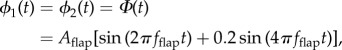
We modelled the wing as a thin plate of uniform thickness, stiffness and density (see figure 2 and table 1). Using Manduca wings as a guide for dimensions, the chord and span were set to 25 mm and 50 mm, respectively. The plate consisted of four nodes, each having three local degrees of freedom: two angular degrees of freedom about the local x- and y-axes, ϕi(t) and θi(t) respectively, and one displacement degree of freedom along the local z-axis, δi(t). To be consistent with our experimental set-up, the positions and angles of the two nodes at the base of the wing (nodes 1 and 2 in figure 2) were prescribed as follows:
 |
2.1a |
| 2.1b |
| 2.1c |
where Aflap is the amplitude of flapping, fflap is the wingbeat frequency and t is time. We did not allow any of the nodes to move in the local x- and y-directions (i.e. no stretching of the wing), but we did allow for displacement in the global X-, Y-, and Z-directions.
Figure 2.

Diagram of the computational wing model, where symbols indicate the following: w(x, y, t) is the z-displacement of the surface, which varies in space (x, y) over the surface of the wing and also in time, t; and ω(t) is the angular velocity of the body frame about the inertial Z-axis. The inertial frame, denoted by S, corresponds to the X, Y and Z axes, and the local frame of the wing, denoted by A, is defined by the x, y and z axes. Orange spheres illustrate the nodes of the computational model. Nodes 1 and 2 are prescribed to move according to a single d.f., which is a flapping input about the local x-axis. Nodes 3 and 4 are allowed three local degrees of freedom shown in inset: rotation about the local x-axis, ϕi(t), twist about the local y-axis, θi(t), and vertical displacement along the local z-axis, δi(t).
Table 1.
List of symbols.
| ϕi | angular displacement of ith node about the x-axis |
| θi | angular displacement of ith node about the y-axis |
| δi | linear displacement of ith node along the z-axis |
| Φ | input flapping angle |
| Aflap | amplitude of flapping |
| fflap | frequency of flapping |
| w(x, y, t) | displacement of wing surface along z-axis |
| a | half of chord length |
| b | half of span length |
| h | thickness |
| ω(t) | time varying angular velocity of the body about z-axis |
| Arot | amplitude of angular velocity |
| frot | frequency of angular velocity |
| ωc | constant angular velocity of the body about z-axis |
| SΩA | vector of angular velocity of the body |
| ɛyy,F | normal strain along y-axis while flapping |
| ɛxx,F | normal strain along x-axis while flapping |
| ɛxy,F | shear strain in x–y plane while flapping |
| ɛyy,F&R | normal strain along y-axis while flapping and rotating |
| ɛxx,F&R | normal strain along x-axis while flapping and rotating |
| ɛxy,F&R | shear strain in x–y plane while flapping and rotating |
| Δɛyy | difference in normal strain along y-axis between flapping versus flapping and rotating |
| Δɛxx | difference in normal strain along x-axis between flapping versus flapping and rotating |
| Δɛxy | difference in shear strain in x–y plane between flapping versus flapping and rotating |
| DL | displacement of the left wing tip in z-direction |
| DR | displacement of the right wing tip in z-direction |
| ΔDF | difference in z-displacement of left and right wing tips while flapping |
| ΔDF&R | difference in z-displacement of left and right wing tips while flapping and rotating |
| Δz | difference in z-displacement of wing surface for flapping versus flapping and rotating |
| F { } | Fourier transform operator |
With the two nodes at base of the wing constrained, our wing model had 6 d.f. remaining at nodes 3 and 4 (figure 2). Thus, a vector, q(t), of the generalized coordinates is given by
| 2.2 |
where δi is the linear displacement of the ith node along the z-axis, ϕi is the angular displacement of the ith node about the x-axis and θi is the angular displacements of the ith node about the y-axis.
We assumed that the displacement of the plate could be described by
| 2.3 |
where q(t) is the vector of generalized displacements given by equation (2.2) and N(x, y) is a vector of shape functions that satisfy the boundary conditions [37]. For our model, we chose shape functions derived from fourth-order polynomials ([38]; see electronic supplementary material for details). Although this model has a limited ability to capture the higher modes of vibration, our goal was not to explore all that is physically possible. We chose this reduced order model as a more computationally efficient, yet sufficiently accurate, approach to explore the underlying dynamics that develop when a wing is flapped and also rotated. Moreover, the results generated by this computational model agree quite well with those measured experimentally (see Results).
The position of all points, m, on the plate's surface in the plate's reference frame, A, is therefore given by
| 2.4 |
where x and y describe the position of each point in space, t is time and w(x, y, t) is given by equation (2.3). For simplicity, we only allowed the flapping wing to rotate globally about the root of the support edge (i.e. body rotation with zero translation). Owing to our simplified dynamics, the angular velocity, Ω, of the wing's reference frame, A, in the inertial frame, S, was therefore
| 2.5 |
where Φ is the flapping rotation about the X-axis, which is prescribed at nodes 1 and 2 by equation (2.1a), and ω(t) is the rotation of the body about the Z-axis.
In one set of simulations, we set the angular velocity of the body to be a constant value equal to the maximum angular yaw velocity of 800° s−1 encountered by Manduca during flight [39]. However, since insects rarely perform manoeuvres at constant angular velocities in their natural environment, we also simulated a periodic angular velocity of the body. Thus, in the computational model, the angular velocity of the body was either described by
| 2.6a |
or
| 2.6b |
where frot is the frequency of the rotation and Arot is the amplitude of the rotation. In the case of periodic rotation (equation (2.6b)), the frequency and amplitude of the rotation were set to 3 Hz and 10°, respectively. We based the frequency of body rotation on previous experiments of Manduca subject to actual and simulated whole-body rotations [16,18]. The amplitude of the rotation was set by the amount of maximum rotation that we could achieve in our experimental set-up (see next section).
With the position of all points on the plate's surface given by equation (2.4) and the angular velocity of the wing in the inertial frame given by equation (2.5), we derived the equations of motion for a wing subjected to rotation using Lagrange's equations (see electronic supplementary material). The general form of this system of equations is given by
 |
2.7 |
where q(t) is the vector of generalized coordinates (equation (2.2)) for which we solved, M−1 is the inverse of the mass matrix, Ma is the applied acceleration mass matrix, vo is a vector that describes the linear velocities of and angular velocities about basal nodes of the wing, Φ is the prescribed input flapping (equation (2.1a)), K is the stiffness matrix due to strain energy of the plate, Ic is an inertia-like matrix that describes the contribution of the Coriolis force, R is the rotation matrix between the body and the wing, SΩA is the angular velocity of the wing in the inertial frame and η is the damping factor. The terms on the right-hand side correspond to the angular acceleration of the plate due to the initial conditions, the centrifugal force, the stiffness of the plate, the Coriolis force and the wing damping, respectively.
We solved this system of second-order ordinary differential equations for the generalized coordinate vector q(t) over 10 rotation cycles, starting from rest, using a fourth-order Runge–Kutta method in MATLAB (The MathWorks, Natick, MA, USA). Simulations were run under five different conditions: flapping alone, constant rotation alone, periodic rotation alone, a combination of both flapping and constant rotation, and a combination of both flapping and periodic rotation.
We reported our results from the computational model using the position of the wing's tips and strain near the wing's base. The right and left wing tip positions (DR and DL, respectively) are given by
| 2.8a |
and
| 2.8b |
where a is half of the chord length, b is half of the span length and w(x, y, t) is given by equation (2.3). In addition, the strain is given by
| 2.9a |
where
| 2.9b |
where h is the thickness of the wing, ɛxx(x, y, t) is normal strain in the x-direction, ɛyy(x, y, t) is normal strain in the y-direction and ɛxy(x, y, t) is shear strain in the x–y plane.
2.2. Robotically actuated model with position tracking
To validate the results of our computational model, we built a robotic actuator to oscillate a model insect wing in a flapping motion while also rotating it about an orthogonal axis (figure 3). This experimental set-up was used to measure the displacement of the tips of a model wing actuated in air.
Figure 3.
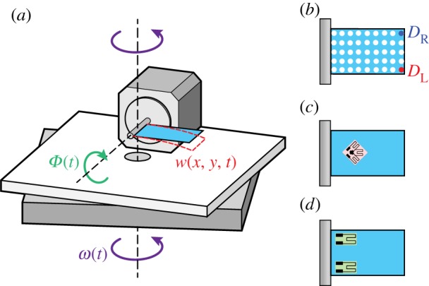
Diagram of the robotically actuated wing set-up (a), where Φ(t) is the flapping input and ω(t) is the angular velocity input about the vertical. The model wing is viewed from the side and a trace of its displacement, w(x, y, t), (dashed red line) corresponds to w(x, y, t) in the computational model (figure 2). To measure displacement, the wing model was marked with correction fluid to create a 5 × 9 grid of fiduciary markers (b). To measure strain, strain gauges were adhered to the wing's surface. In the case of shear strain, a single rosette was placed at about one-fourth span along the mid-chord (c). When evaluating normal strain, two linear strain gauges were applied to either side of the wing's base (d).
By optically tracking the position of the wing, we measured the dynamics of wing deformation during a combination of flapping and body rotation. Our model wing consisted of a 50 × 25 mm acrylic sheet with a flexural stiffness of 10−5 Nm2 that well approximated a Manduca forewing [20]. To track bending during each trial, we drew a 5 × 9 grid of fiduciary markers on our wing model with correction fluid (figure 3b). The model wing was attached to the shaft of a servomotor controlled by a length driver (Model 305B Dual-Mode Lever Arm System, Aurora Scientific Inc., Aurora, ON, Canada) and the frequency and amplitude of the flapping oscillation were controlled with a function generator (3311A Function Generator, Hewlett-Packard, Palo Alto, CA, USA). The oscillation amplitude (15°) was constrained by the motor power and was lower than that of Manduca. However, the wing was flapped at the typical Manduca wingbeat frequency of 25 Hz.
We secured the robotic actuator onto a rigid aluminium frame that was mounted to a stepper motor [16]. To be consistent with our computational model, the rotation of this motor was controlled using a custom Arduino script that generated a 10°, 3 Hz sinusoid about the z-axis via a micro-step controller (G201, GeckoDrive Inc., Tustin, CA, USA). We mounted a high-speed camera (Phantom Miro, Vision Research, NJ, USA) to the frame and recorded at 500 frames s−1, with a 400 µs shutter speed. An orthogonal view of the wing was provided by a mirror attached to the frame above the model wing in the view of the camera.
We measured wing tip motions under the following conditions: flapping alone, rotation alone, and flapping and rotation. All trials were conducted for 10 s to allow the system to reach steady-state motion. We digitized the videos using a custom MATLAB script (The MathWorks, Natick, MA, USA), tracking six points on the model wing: the free ends of the top and bottom of the wing, and the two corners at the base of the wing. To be consistent with the results from our computational model, these values were reported using the variables DR for the right wing tip and DL for the left wing tip (see equation (2.8a,b)).
2.3. Robotically actuated model with strain measurement
A second experimental system allowed us to measure model wing strain during a combination of flapping and rotation about the z-axis. The model wing consisted of a piece of 50 × 25 mm acrylic with a thickness of 127 µm. To measure shear strain, we glued a 350 Ω rosette strain gauge (SGD-2/350-RY53, Omega Engineering Inc., Stamford, CT, USA) to the wing at about one-fourth of the span along the mid-chord (figure 3c). The rosette was placed such that two of the strain gauges in the rosette were aligned at 45° to the span with the remaining gauge coincident with the mid-chord. Since our primary interest was to detect shear strain caused by torsion, recordings were only taken from the two strain gauges oriented at 45° to the span. For the measurement of normal strain, we glued two 350 Ω linear strain gauges (KFH-3/350-C1, Omega Engineering Inc., Stamford, CT, USA) onto either edge of the chord at the base of a separate model wing (figure 3d). In all cases, the strain gauges were connected in separate quarter-bridge configurations so that we could measure the strain of each gauge independently.
The model wing was attached onto a camshaft set-up designed to produce sinusoidal motion (25 Hz, 15°) using the previously mentioned function generator. As in the prior experimental set-up, the system was actuated in air with periodic (3 Hz, 10°) rotation about the z-axis. We measured wing strain under the same conditions as the prior set-up: flapping alone, rotation alone, and flapping and rotation. Signals from the strain gauges were amplified 100× (Transbridge 4M, WPI, Sarasota, FL, USA) and sampled at 5 kHz (USB-6008, National Instruments, Austin, TX, USA).
3. Results
We summarize computational results for flapping wings subject to constant yaw rotation as well as periodic yaw (z) rotations in the following section. The latter are compared with experimental results for flapping wings subject to periodic yaw rotations.
3.1. Torsional deformation emerges from a combination of flapping and constant yaw rotation in the computational model
Simulations from the computational model revealed that wings subject to both flapping (25 Hz, 15°) and constant yaw rotation (ωc = 800° s−1) exhibit torsional deformations (figure 4). These results are seen in the temporal pattern of tip displacements (DR and DL). The difference between these displacements (i.e. the relative tip displacement, DL − DR; figure 4c) is about 100 times smaller than the absolute tip displacement (figure 4a). Though small, this difference in the displacement of the two wing tips during concurrent flapping and rotation (solid line in figure 4c) is indicative of wing torsion. This phenomenon is not seen in either pure flapping or pure rotation (dashed line in figure 4c). Moreover, the double peaks in the sinusoidal pattern of deformation during flapping and rotation (dashed lines in figure 4c) occur at twice the flapping frequency and are therefore a signature of the Coriolis force. Indeed, when we reverse the direction of the angular velocity (i.e. ωc = −800° s−1), the peaks that occur at twice the flapping frequency due to the Coriolis force also reverse sign (figure 4d).
Figure 4.

The displacements of the left (DL, solid red) and right (DR, dashed blue) wing tips of the computational wing model are very similar over time, t, for flapping alone (a). When the wing twists due to an applied constant rotation, ωc, illustrated in (b), the difference between these two tip displacements changes. This difference is effectively zero when the wing is just flapping (dashed lines in (c) and (d)). However, when the wing is flapping while also rotating (solid lines in (c) and (d)), the difference in tip displacement oscillates at wingbeat frequency and twice wingbeat frequency. When the sign of the rotation is reversed, the signature at twice the wingbeat frequency (indicative of the Coriolis force) also reverses sign (d). (Online version in colour.)
To further explore the dynamics of Coriolis-induced wing torsion, we plotted the differences in wing deformation and strain with and without constant yaw rotation at several snapshots in time during a single period of flapping (figure 5). While the differences in normal strain in the span-wise (y) direction (figure 5c) and shear strain in the x–y plane (figure 5e) are of the same order of magnitude (0.001% strain), the difference in the normal strain along the chord-wise (x) direction (figure 5d) is about 100 times smaller. This difference in chord-wise normal strain is due to changes in span-wise lengthening generated by the tiny centrifugal forces produced by wing flapping combined with the Poisson effect: the model wing compresses in the chord-wise direction as it is stretched in the span-wise direction. As a result, the largest differences in chord-wise normal strains are near the tip of the wing because that is where the span-wise lengthening is greatest.
Figure 5.

Torsion emerges in the computational model when the wing is flapped while it is also rotated at constant angular velocity of 800° s−1. As shown in (a), the input flapping angle, Φ, varies over the relative time in the flapping cycle, t/T. The displacement of the model wing and the strain at its surface change in both space and time. At several snapshots in time (indicated by the filled circles and dotted vertical lines in (a)), spatial contours of the difference between flapping and rotating versus flapping alone are shown for four parameters: displacement, Δz (b); normal strain along the y-axis, Δɛyy (c); normal strain along the x-axis, Δɛxx (d); and shear strain in the x−y plane, Δɛxy (e). Colouring refers to the magnitude of each parameter as indicated by the colour bars on the far left.
Additionally, the difference in normal strain in the span-wise (y) direction displays peak regions that oscillate from side-to-side near the base of the wing. On the other hand, the difference in shear strain is largest in the centre of the wing. These observations are consistent with theoretical results for a plate undergoing torsion [40]: maximum shear strain occurs at the centre of the plate and maximum normal strain along the span-wise direction occurs at the base of the plate. Thus, when the plate undergoes rotation while flapping, a new mode of deformation appears: torsion.
3.2. Wing tip deformation reveals torsion in flapping wings subject to periodic yaw rotation in both computational and physical models
As mentioned above, for both experimental convenience and biological relevance, we examined tip deformations in both computational and experimental wings subject to a combination of flapping and periodic yaw rotations. This approach provided a direct validation of our computational results. Since our robotic models were actuated in air, they also include aerodynamic loading and therefore allow us to examine the relative impact of aerodynamic forces. As prior work showed that aerodynamic forces do not contribute substantially to wing bending at the scale of Manduca [21], we expected our experimental and computational results for wing torsion to be very similar.
Indeed, we observed strong similarities between the relative tip displacement (i.e. difference between the model wing's two free ends, ΔD) of our computational and experimental results (figure 6). When subject to flapping alone, the relative tip displacement is zero for the computational model (figure 6a). While the relative tip displacement during flapping alone is not exactly zero in the physical experiment, it is quite small (approx. 5 µm) and rather noisy (figure 6d). By contrast, during the combination of flapping and rotating about an orthogonal axis, the relative tip displacement is much larger (approx. 50 µm) and strongly periodic (figure 6e). This result holds true for both the computational (figure 6b) and robotic (figure 6e) models.
Figure 6.

The difference between the displacement of the left (DL) and right (DR) wing tips, ΔD versus time, t, for flapping alone (a,d) and flapping and rotating with periodic angular velocity (b,e). The subscripts of ΔD are F for flapping alone and F&R for flapping and rotating. Time domain results for a time-average taken over 10 rotation cycles are shown for computational (a–b) and experimental (d–e) models. Shading denotes standard deviation. Frequency domain results of the difference in amplitude of the FFTs of ΔD for flapping and rotating compared with flapping alone for the computational (c) and experimental (f) models. Note the peaks at the flapping frequency of 25 Hz, plus and minus the rotation frequency of 3 Hz. (Online version in colour.)
To determine the frequencies present in these periodic signals, we computed the fast Fourier transforms (FFTs) of the relative tip displacements and evaluated the difference between the amplitudes of the FFTs for flapping alone and flapping and rotating (see electronic supplementary material for further explanation). Our results show strong peaks at the imposed flapping frequency of 25 Hz ± rotation frequency (3 Hz) for both our computational and physical models (figure 6c,f). This phenomenon, known as amplitude modulation, results from the Coriolis force, which is proportional to the angular velocity (a sine wave at rotation frequency) crossed with the velocity of the wing (a cosine wave at wingbeat frequency). Using the product-to-sum trigonometric identity,
| 3.1 |
Thus, the Coriolis force causes torsional oscillations at wingbeat frequency, modulated by the rotation frequency. Moreover, the magnitudes of these oscillations in relative tip displacement (figure 6c,f) are about three orders smaller than the absolute tip displacement (approx. 30 mm).
3.3. Torsion caused by rotational perturbations of flapping wings is reflected in wing strain
The Coriolis-induced torsion that we observed via relative wing tip displacement is also reflected in the spatio-temporal patterns of shear and normal strain. For both flapping alone and flapping with imposed periodic body rotation, our computational and experimental results exhibit periodic shear (figure 7) and normal (figure 8) strain. Shear strain, as measured near the base of the wing at the mid-chord, is on the order of 0.01% strain. On the other hand, normal strain, as measured in the span-wise direction at either side of the wing base, is an order of magnitude larger (0.2% strain). As expected, when the wing is subjected to body rotation alone, both shear and normal strain are zero (data not shown). In all cases, the experimental and computational models exhibit equivalent strain dynamics.
Figure 7.

The shear strain at the quarter span along the mid-chord ɛxy versus time, t, for flapping alone (a,d) and flapping and rotating with periodic angular velocity (b,e). The additional subscripts of ɛxy are F for flapping alone and F&R for flapping and rotating. Time domain results for a time-average taken over 10 rotation cycles are shown for computational (a–b) and experimental (d–e) models. Shading denotes standard deviation. Frequency domain results of the difference in amplitude of the FFTs of ɛxy for flapping and rotating compared to flapping alone for the computational (c) and experimental (f) models. Note the peaks at the flapping frequency of 25 Hz, plus and minus the rotation frequency of 3 Hz, and their harmonics. (Online version in colour.)
Figure 8.

The normal strain along the span-wise direction, ɛyy, on either side of the wing's chord (left side, solid; right side, dashed) near the base of a model wing versus time, t, for flapping alone (a,d) and flapping and rotating with periodic angular velocity (b,e). The additional subscripts of ɛyy are F for flapping alone and F&R for flapping and rotating. Time domain results for a time-average taken over 10 rotation cycles are shown for computational (a–b) and experimental (d–e) models. Shading denotes standard deviation. Frequency domain results of the difference in amplitude of the FFTs of the difference between the left and right normal strains, Δɛyy, for flapping and rotating compared with flapping alone for the computational (c) and experimental (f) models. Note the peaks at the flapping frequency of 25 Hz, plus and minus the rotation frequency of 3 Hz, and their harmonics. (Online version in colour.)
The difference between flapping with versus without body rotation for both shear and normal strain is difficult to discern looking at the two signals side by side (e.g. figures 7a,b and 8a,b). Since the experimental results for pure flapping versus combined flapping and rotating are not phase-matched, we cannot perform a simple subtraction. As such, we instead computed the FFTs of the strains under each condition and then computed the difference between the magnitudes of the FFTs. We performed this analysis separately for both shear and normal strain under the two conditions of flapping with and without body rotation (figures 7c,f and 8c,f). Similar to the displacement (figure 6), both shear and normal strain exhibit sharp peaks at the wingbeat frequency ± the rotation frequency and its first harmonic. The experimental results also have additional peaks at wingbeat frequency and its harmonics, which are likely due to our inability to exactly control the flapping frequency in the experiment (e.g. less than 1% difference in frequency causes the difference of the FFTs to have large peaks at the flapping frequency—see electronic supplementary material).
Our computational results for periodic yaw (z) rotation also show spatio-temporal patterns of shear and normal strains on the surface of the wing that are similar to those noted above for constant rotation (figure 5). As for constant rotation, the maximum and minimum values of the difference span-wise normal strains between flapping and rotating versus flapping alone oscillate near the base of the wing (see electronic supplementary material). Moreover, as during constant rotation, the maximum and minimum values of the difference in the shear strains between flapping with versus without periodic rotation are largest at the centre of the wing. However, in the case of periodic rotation, the magnitude of the strain varies at both the wingbeat frequency and the frequency of the yaw rotation.
4. Discussion
As flapping, flexing and flight-force generating structures, insect wings are subject to a host of aerodynamic and inertial forces. These forces, in turn, interact with the wings' structural dynamics to generate complex spatial and temporal patterns of deformation. In this study, we undertook a series of computational and experimental approaches to investigate how such patterns of wing deformation depend upon body rotations. Our work was motivated, in part, by the notion that wings, as evolutionary antecedents of halteres, might themselves provide information about body dynamics. Additionally, biological systems might provide inspiration for new ways to generate gyroscopic sensory devices.
Our goal here was to reveal the principles that govern the structural dynamics of flapping insect wings during body rotations. As a result, we only considered simplified flapping kinematics and assumed a flexible plate of uniform stiffness and mass distribution. In actuality, insect wings are neither homogeneously stiff [41] nor do they have uniform mass distribution. Factoring in these characteristics may affect the torsional dynamics and change the strain distribution on wings. Regardless, we have uncovered a unique mechanism that easily enables the wings to detect information previously thought to require complex neural processing [42].
Here we found that flapping, flexible wings subject to rotations about an orthogonal axis reveal a pattern of torsional deformation not noted previously. In addition, wings exhibit periodic normal and shear strains that are a direct consequence of the Coriolis forces acting on them. During rotations, these changes in strain could stimulate embedded mechanoreceptors and trigger correctional reflexes. In this way, insect wings would serve a role similar to halteres, the prototypical biological gyroscopes.
4.1. Insect wings undergo torsion during body rotations, resulting in spatio-temporally varying strain
Whereas a great deal of effort has gone into understanding the causes of wing bending, torsion in insect wings has received far less attention. Much of the focus in this regard pertains to measuring the torsional stiffness of insect wings [25] or understanding the basis for torsion during hovering flight [22]. Ennos [22], for example, concluded that torsion in hoverfly wings was due primarily to inertial forces. But inertial forces in a rotating reference frame arise from both rectilinear and rotational accelerations, one of which is the acceleration arising from the superposition of orthogonal rotational motions (the Coriolis acceleration). Thus, the inertial forces that result from body rotations could cause wing torsion and thereby convey information about rotation rate.
Our computational results reveal a complex spatio-temporal pattern of strain that arises when flapping wings are subject to rotation about an axis orthogonal to their flapping, as during a body rotation. Whether we simulate constant or periodic body rotation, three key results emerge. First, wings undergo a large bending deflection along the span driven by inertial bending moments produced by flapping. This result is consistent with prior studies highlighting the dominant role of inertial and elastic mechanisms underlying wing and haltere deformation [3–5,21,43]. Second, superimposed upon that large bending deformation is a smaller torsional deformation that is seen in the difference of the tip displacement at the corners of our rectangular wing. In contrast to the minuscule lateral deflections suggested for halteres subject to Coriolis forces, the high lateral second moment of area of wings prohibits any such deformation and thus torsion emerges. Third, wing torsion appears as periodic patterns of shear and normal strains distributed over the wing surface. In contrast to normal strains, where the dominant signal arises from in-plane bending, shear strains directly measure torsion and are insensitive to the large in-plane bend.
4.2. Changes in wing strain could stimulate mechanosensors, enabling insects to detect body rotation
In halteres, the detection of Coriolis forces is thought to require extreme directional sensitivity of the campaniform sensilla in order to respond to exceedingly small lateral deflections in the presence of large in-plane bending moments that result from haltere flapping [3,6]. While such sensitivity has been suggested for campaniform sensilla [44], wing campaniform sensilla are highly unlikely to experience lateral deflections analogous to those suggested for halteres. Perhaps alternate mechanisms, which combine our results with previous results on the neural timing precision of campaniform sensilla, suggest other ways to detect Coriolis forces.
One possible mechanism could involve detecting the temporal separation of peak strain as opposed to changes in strain magnitude. We show that the magnitudes of peak normal strains at the wing base are large and that the small differences that arise from Coriolis-induced torsion result in shifts in the timing of peak strain. As has been suggested for halteres [45], this spatio-temporal pattern of wing strain could be encoded by the nervous system using subtle shifts in the phase of firing of campaniform sensilla across the wing. While this encoding strategy would require a high level of temporal precision from wing campaniforms, high temporal precision is a hallmark of campaniform sensilla on halteres [45–49] and wings [18]. In fact, the detection of the wing torsion dynamics that we observed is well within the encoding bandwidth limits of campaniform sensilla. Moreover, recent computational work suggests that the incorporation of neuronal filters, which capture aspects of a signal's time history, onto the strain field of a flapping flexing plate enhances the ability to detect body rotation [50]. Thus, rather than relying on magnitude alone, gyroscopic sensing may require an encoding strategy that includes both the spatial and temporal aspects of strain.
No matter how the strain sensing occurs, this unique sensory role through the process of actuation would make the wing both a sensor and an actuator. That is, by flapping for propulsion and manoeuvrability, the wing and its embedded campaniform sensilla could detect phenomena during perturbations or manoeuvres that would be otherwise unavailable to the animal. This sensory role for the wings could predate their evolutionary modification into halteres, organs with a demonstrated capability for sensing angular velocity.
5. Conclusion
We propose that insects can detect the angular velocity of their body via changes in the structural dynamics of their wings. Through the development of computational and robotically actuated wing models, we show that torsion emerges when a flapping, flexing wing is subject to body rotations. This torsion leads to an increase in strain over the wing's surface, which could stimulate the campaniform sensilla embedded in the wing and thereby trigger compensatory reflexes. Thus, we demonstrate that there is indeed a unique structural dynamic mode that develops in the wing, which could inform an insect about its body dynamics.
These results have broad implications for our understanding of biological gyroscopes and for the design of engineered systems. For example, our results indicate that information about body dynamics could be determined by embedding strain gauges directly onto the surface of flexible aerofoils already being actuated for propulsion or energy harvesting (e.g. micro air vehicles, turbine blades and helicopter blades). Since the spatio-temporal pattern of strain has implications for optimal sensor placement, future work will examine the extent to which this information might allow us to (i) identify the biological placement of campaniforms on insect wings and (ii) inform sensor design for engineered systems. Furthermore, our results suggest that the time has come for a re-examination of the haltere's structural dynamics. Future work will modify prior haltere models to allow for torsional deformation and test hypotheses regarding the importance of temporal encoding.
Through the exploration of biological gyroscopes, we have uncovered principles that might be useful for engineering design. Conversely, our use of engineering analysis has provided insight into the form and function of the mechnanosensory structures embedded in insect wings.
Supplementary Material
Acknowledgements
The authors thank Bing Brunton, Eatai Roth, Kristi Morgansen, Brian Hinson and the Daniel Lab for useful discussions and comments on this manuscript.
Data accessibility
The code for our computational model and our computational and experimental data are available at https://github.com/eberlea/TorsionWing.
Funding statement
This work was supported by AFOSR grant no. FA9550-11-1-0155 to T.L.D. as well as the Komen Endowed Chair and ONR MURI grant no. N000141010952 to T.L.D. B.H.D. and A.L.E. also received funding from NSF GRFP (DGE-0718124).
Conflict of interest
We have no competing interests.
References
- 1.Land MF, Collett TS. 1974. Chasing behaviour of houseflies (Fannia canicularis). J. Comp. Physiol. A 89, 331–357. ( 10.1007/BF00695351) [DOI] [Google Scholar]
- 2.Theobald JC, Warrant EJ, O'Carroll DC. 2010. Wide-field motion tuning in nocturnal hawkmoths. Proc. R. Soc. B 277, 853–860. ( 10.1098/rspb.2009.1677) [DOI] [PMC free article] [PubMed] [Google Scholar]
- 3.Pringle JWS. 1948. The gyroscopic mechanism of the halteres of Diptera. Phil. Trans. R. Soc. Lond. B 233, 347–384. ( 10.1098/rstb.1948.0007) [DOI] [Google Scholar]
- 4.Nalbach G. 1993. The halteres of the blowfly Calliphora I. Kinematics and dynamics. J. Comp. Physiol. A 173, 293–300. ( 10.1007/BF00212693) [DOI] [Google Scholar]
- 5.Thompson RA, Wehling MF, Evers JH, Dixon WE. 2008. Body rate decoupling using haltere mid-stroke measurements for inertial flight stabilization in Diptera. J. Comp. Physiol. A 195, 99–112. ( 10.1007/s00359-008-0388-1) [DOI] [PubMed] [Google Scholar]
- 6.Fraenkel G, Pringle JWS. 1938. Halteres of flies as gyroscopic organs of equilibrium. Nature 141, 919–20. ( 10.1038/141919a0) [DOI] [Google Scholar]
- 7.Hengstenberg R. 1988. Mechanosensory control of compensatory head roll during flight in the blowfly Calliphora erythrocephala Meig. J. Comp. Physiol. A 163, 151–165. ( 10.1007/BF00612425) [DOI] [Google Scholar]
- 8.Nalbach G, Hengstenberg R. 1994. The halteres of the blowfly Calliphora II. Three-dimensional organization of compensatory reactions to real and simulated rotations. J. Comp. Physiol. A 175, 695–708. ( 10.1007/BF00191842) [DOI] [Google Scholar]
- 9.Dickinson MH. 1999. Haltere-mediated equilibrium reflexes of the fruit fly, Drosophila melanogaster. Phil. Trans. R. Soc. Lond. B 354, 903–916. ( 10.1098/rstb.1999.0442) [DOI] [PMC free article] [PubMed] [Google Scholar]
- 10.Voss R, et al. 1997. Silicon angular rate sensor for automotive applications with piezoelectric drive and piezoresistive read-out. In IEEE Int. Conf. on Solid-state Sensors and Actuators, pp. 879–82, 16–19 June, Chicago, IL Piscataway, NJ: IEEE Press. [Google Scholar]
- 11.Funk K, Emmerich H, Schilp A, Offenberg M, Neul R, Larmer F. 1999. A surface micromachined silicon gyroscope using a thick polysilicon layer. In 12th Ann. IEEE Int. Conf. on Micro Electro Mechanical Systems, pp. 57–60, 17–21 Jan, Orlando, FL Piscataway, NJ: IEEE Press. [Google Scholar]
- 12.Wu WC, Wood RJ, Fearing RS. 2002. Halteres for the micromechanical flying insect. 2002 IEEE pp. 60–65. [Google Scholar]
- 13.Bhadbhade V, Jalili N, Nima Mahmoodi S. 2008. A novel piezoelectrically actuated flexural/torsional vibrating beam gyroscope. J. Sound Vib. 311, 1305–1324. ( 10.1016/j.jsv.2007.10.017) [DOI] [Google Scholar]
- 14.Pix W, Nalbach G, Zeil J. 1993. Strepsipteran forewings are haltere-like organs of equilibrium. Naturwissenschaften 80, 371–374. ( 10.1007/BF01138795) [DOI] [Google Scholar]
- 15.Sane SP, Dieudonne A, Willis MA, Daniel TL. 2007. Antennal mechanosensors mediate flight control in moths. Science 315, 863–866. ( 10.1126/science.1133598) [DOI] [PubMed] [Google Scholar]
- 16.Hinterwirth AJ, Daniel TL. 2010. Antennae in the hawkmoth Manduca sexta (Lepidoptera, Sphingidae) mediate abdominal flexion in response to mechanical stimuli. J. Comp. Physiol. A 196, 947–956. ( 10.1007/s00359-010-0578-5) [DOI] [PubMed] [Google Scholar]
- 17.Hinterwirth AJ, Medina B, Lockey J, Otten D, Voldman J, Lang JH, Hildebrand JG, Daniel TL. 2012. Wireless stimulation of antennal muscles in freely flying hawkmoths leads to flight path changes. PLoS ONE 7, e52725 ( 10.1371/journal.pone.0052725) [DOI] [PMC free article] [PubMed] [Google Scholar]
- 18.Dickerson BH, Aldworth ZN, Daniel TL. 2014. Control of moth flight posture is mediated by wing mechanosensory feedback. J. Exp. Biol. 217, 2301–2308. ( 10.1242/jeb.103770) [DOI] [PubMed] [Google Scholar]
- 19.Chen J-S, Chen J-Y, Chou Y-F. 2008. On the natural frequencies and mode shapes of dragonfly wings. J. Sound Vib. 313, 643–654. ( 10.1016/j.jsv.2007.11.056) [DOI] [Google Scholar]
- 20.Combes SA, Daniel TL. 2003. Flexural stiffness in insect wings. II. Spatial distribution and dynamic wing bending. J. Exp. Biol. 206, 2989–2997. ( 10.1242/jeb.00524) [DOI] [PubMed] [Google Scholar]
- 21.Combes SA, Daniel TL. 2003. Into thin air: contributions of aerodynamic and inertial–elastic forces to wing bending in the hawkmoth Manduca sexta. J. Exp. Biol. 206, 2999–3006. ( 10.1242/jeb.00502) [DOI] [PubMed] [Google Scholar]
- 22.Ennos A. 1988. The importance of torsion in the design of insect wings. J. Exp. Biol. 140, 137–160. [Google Scholar]
- 23.Walker SM, Thomas ALR, Taylor GK. 2009. Deformable wing kinematics in the desert locust: how and why do camber, twist and topography vary through the stroke? J. R. Soc. Interface 6, 735–747. ( 10.1098/rsif.2008.0435) [DOI] [PMC free article] [PubMed] [Google Scholar]
- 24.Wootton RJ. 1992. Functional morphology of insect wings. Annu. Rev. Entomol. 37, 113–140. ( 10.1146/annurev.en.37.010192.000553) [DOI] [Google Scholar]
- 25.Wootton RJ. 1993. Leading edge section and asymmetric twisting in the wings of flying butterflies (Insecta, Papilionoidea). J. Exp. Biol. 180, 105–117. [Google Scholar]
- 26.Norris AG, Palazotto AN, Cobb RG. 2010. Structural dynamic characterization of an insect wing. In 51st AIAA/ASME/ASCE/AHS/ASC Structures, Structural Dynamics, and Materials Conf., 12–15 April 2010, Orlando, FL. [Google Scholar]
- 27.Mountcastle AM, Daniel TL. 2010. Vortexlet models of flapping flexible wings show tuning for force production and control. Bioinspir. Biomim. 5, 045005 ( 10.1088/1748-3182/5/4/045005) [DOI] [PubMed] [Google Scholar]
- 28.Young J, Walker SM, Bomphrey RJ, Taylor GK, Thomas ALR. 2009. Details of insect wing design and deformation enhance aerodynamic function and flight efficiency. Science 325, 1549–1552. ( 10.1126/science.1175928) [DOI] [PubMed] [Google Scholar]
- 29.Vanella M, Fitzgerald T, Preidikman S, Balaras E, Balachandran B. 2009. Influence of flexibility on the aerodynamic performance of a hovering wing. J. Exp. Biol. 212, 95–105. ( 10.1242/jeb.016428) [DOI] [PubMed] [Google Scholar]
- 30.Nakata T, Liu H. 2012. Aerodynamic performance of a hovering hawkmoth with flexible wings: a computational approach. Proc. R. Soc. B 279, 722–731. ( 10.1098/rspb.2011.1023) [DOI] [PMC free article] [PubMed] [Google Scholar]
- 31.Eberle AL, Reinhall PG, Daniel TL. 2014. Fluid–structure interaction in compliant insect wings. Bioinspir. Biomim. 9, 025005 ( 10.1088/1748-3182/9/2/025005) [DOI] [PubMed] [Google Scholar]
- 32.Veers P, Lobitz D, Bir G. 1998. Aeroelastic tailoring in wind-turbine blade applications. Albuquerque, NM: Sandia National Labs. [Google Scholar]
- 33.Friedmann PP. 2004. Rotary-wing aeroelasticity: current status and future trends. AIAA J. 42, 1953–1972 [Google Scholar]
- 34.Sreenivasamurthy S, Ramamurti V. 1981. Coriolis effect on the vibration of flat rotating low aspect ratio cantilever plates. J. Strain Anal. Eng. Des. 16, 97–106. ( 10.1243/03093247V162097) [DOI] [Google Scholar]
- 35.Jankauski M, Shen IY. 2014. Dynamic modeling of a rotating insect wing. In Proc. Int. Micro Air Vehicle Conference, Delft, The Netherlands. [Google Scholar]
- 36.Rayleigh L. 1877. The theory of sound, vol. 1. New York, NY: Macmillan; (reprinted 1945 by Dover Publications, New York, NY). [Google Scholar]
- 37.Reddy JN. 2004. An introduction to the finite element method, 3rd edn New York, NY: McGraw Hill. [Google Scholar]
- 38.Melosh RJ. 1963. Basis of derivation of matrices for the direct stiffness method. AIAA J. 1, 1631–1637. ( 10.2514/3.1869) [DOI] [Google Scholar]
- 39.Hedrick TL, Cheng B, Deng XY. 2009. Wingbeat time and the scaling of passive rotational damping in flapping flight. Science 324, 252–255. ( 10.1126/science.1168431) [DOI] [PubMed] [Google Scholar]
- 40.Reissner E, Stein M. 1951. Torsion and transverse bending of cantilever plates. NACA Technical Note 2369.
- 41.Combes SA, Daniel TL. 2003. Flexural stiffness in insect wings. I. Scaling and the influence of wing venation. J. Exp. Biol. 206, 2979–2987. ( 10.1242/jeb.00523) [DOI] [PubMed] [Google Scholar]
- 42.Chan WP, Prete F, Dickinson MH. 1998. Visual input to the efferent control system of a fly's ‘gyroscope’. Science 280, 289–292. ( 10.1126/science.280.5361.289) [DOI] [PubMed] [Google Scholar]
- 43.Daniel TL, Combes SA. 2002. Flexible wings and fins: bending by inertial or fluid-dynamic forces? Integr. Comp. Biol. 42, 1044–1049. ( 10.1093/icb/42.5.1044) [DOI] [PubMed] [Google Scholar]
- 44.Zill SN, Moran DT. 1981. The exoskeleton and insect proprioception. I. Responses of tibial campaniform sensilla to external and muscle-generated forces in the American cockroach, Periplaneta americana. J. Exp. Biol. 91, 1–24. [Google Scholar]
- 45.Fox JL, Fairhall AL, Daniel TL. 2010. Encoding properties of haltere neurons enable motion feature detection in a biological gyroscope. Proc. Natl Acad. Sci. USA 107, 3840–3845. ( 10.1073/pnas.0912548107) [DOI] [PMC free article] [PubMed] [Google Scholar]
- 46.Chapman KM, Mosinger JL, Duckrow RB. 1979. The role of distributed viscoelastic coupling in sensory adaptation in an insect mechanoreceptor. J. Comp. Physiol. A 131, 1–12. ( 10.1007/BF00613078) [DOI] [Google Scholar]
- 47.Dickinson MH. 1990. Linear and nonlinear encoding properties of an identified mechanoreceptor on the fly wing measured with mechanical noise stimuli. J. Exp. Biol. 151, 219–244. [Google Scholar]
- 48.Dickinson MH. 1990. Comparison of encoding properties of campaniform sensilla on the fly wing. J. Exp. Biol. 151, 245–261. [Google Scholar]
- 49.Fox JL, Daniel TL. 2008. A neural basis for gyroscopic force measurement in the halteres of Holorusia. J. Comp. Physiol. A. 194, 887–897. ( 10.1007/s00359-008-0361-z) [DOI] [PubMed] [Google Scholar]
- 50.Brunton B, Eberle AL, Dickerson B, Brunton S, Kutz JN, Daniel T. 2014. Sensor placement for sparse sensory decision-making. Salt Lake City, UT: COSYNE; See www.cosyne.org. [Google Scholar]
Associated Data
This section collects any data citations, data availability statements, or supplementary materials included in this article.
Supplementary Materials
Data Availability Statement
The code for our computational model and our computational and experimental data are available at https://github.com/eberlea/TorsionWing.