Abstract
A miniaturized, self-contained pacemaker that could be implanted with a minimally invasive technique would dramatically improve the survival rate for fetuses that develop hydrops fetalis as a result of congenital heart block. We are currently validating a device that we developed to address this bradyarrhythmia. Preclinical studies in a fetal sheep model are underway to demonstrate that the device can be implanted via a minimally invasive approach, can mechanically withstand the harsh bodily environment, can induce effective contractions of the heart muscle with an adequate safety factor, and can successfully operate for the required device lifetime of three months using the previously-developed closed loop transcutaneous recharging system.
I. Introduction
Congenital heart block with secondary hydrops fetalis is a life-threatening emergency with no effective treatment options [1, 2]. Fetal bradycardia due to heart block can progress in utero, and for more than a quarter of these fetuses may result in hydrops fetalis [3, 4]. Once hydrops fetalis develops, if the fetus cannot be delivered due to prematurity or other clinical concerns, fetal demise is nearly inevitable [2]. Pharmacological and immunological therapies delivered systemically via the mother have not been effective in clinical trials [5–7].
When a newborn, child or adult presents with symptomatic complete heart block, treatment usually consists of implantation of a pacemaker to ensure an adequate heart rate. With appropriate pacing, these patients are usually asymptomatic with an excellent prognosis. Similar benefits would be expected from pacing a fetus with complete heart block, theoretically allowing resolution of hydrops in 1–2 weeks and permitting an otherwise normal gestation. A conventional pacemaker would then be implanted at delivery. Over the last two decades, several investigators have attempted to place pacemakers in a fetus [8–10]. To date, however, there have been no survivors of fetal pacing. Previous approaches have relied on the placement of a pacing wire on the epicardial surface of the fetal heart via thoracotomy or sternotomy with an extra-uterine pulse generator implanted in the mother. This has inevitably failed because of lead dislodgement due to fetal movement.
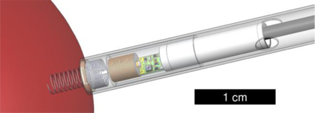
We have designed a single-chamber pacing system that is self-contained and can be percutaneously implanted completely within the fetus without exteriorized leads, thereby permitting subsequent fetal movement without risk of dislodgement of the electrodes (Fig. 1). Such a design is now possible because of significant developments in medical device miniaturization and advances in minimally invasive fetal surgical intervention, allowing the pacing system to be percutaneously deployed through the maternal abdomen and fetal chest under ultrasound guidance.
Figure 1.
The fetal pacemaker includes a corkscrew electrode that anchors the device upon implantation, a short strain relieving lead, a secondary coil and ferrite for recharging, the oscillator circuitry, and a 3 mAh lithium ion cell. The device is shown within a plastic insertion sheath and is held inside by friction of an epoxy disk between the electrode and lead. Once the device location is confirmed, the sheath can be rotated by the surgeon to screw the electrode into the myocardium. A push rod is then used to dislodge the friction disk from the sheath and to eject the pacemaker as the sheath and insertion cannula are retracted.
The tiny power cell within the implanted pacemaker holds sufficient charge to sustain pacing for 1–4 weeks depending on stimulus charge. Many patients will require pacing for 1–3 months before delivery, so we have developed a wireless recharging system for the lithium power cell. The stimulus charge is fixed by the selection of the components. It must provide a reasonable safety factor (twice threshold) to guarantee pacing capture, but excessively frequent recharging is undesirable. We here describe factors that influence pacing threshold, methods to determine safety factor in vivo, and methods to control the recharging process.
II. Insertion of the Epicardial Pacing Electrode
A. Strategy
The implantation of the fetal pacemaker utilizes a percutaneous epicardial approach in order to access the myocardial tissue because of the patient’s extremely small size. Epicardial ventricular pacing avoids some complications of intravascular devices and can provide direct access to the left ventricle, but it normally requires surgical exposure of the heart. We are developing a minimally invasive implantation procedure that utilizes a 3.8 mm i.d. cannula and trocar that are typical for fetal surgeries today. Our first generation device is small enough to implant in a fetus in utero [11], and we are developing a similar approach for children and adults who have restricted venous access, septal defects or other complications [12]. Pacing leads with a helical electrode are used commonly to provide secure anchoring to the endocardial surface. By applying a slight axial pressure and clockwise rotation on the catheter, the electrode can be screwed into myocardium. For a minimally invasive epicardial approach, the design of the electrode must consider the full range of mechanical properties of the connective tissues on the pericardial surfaces of the heart that are be encountered during implantation.
The pacing circuitry and RF-rechargeable lithium cell are contained within an epoxy-filled cylinder, 3.3 mm diameter × 20 mm long. This is attached to a flexible helical lead that connects to the rigid corkscrew electrode at a junction embedded in an epoxy disk. The disk is held by friction in the end of a plastic sheath that carries the pacemaker into the fetus through the 3.8 mm surgical cannula. The device and plastic insertion sheath must be able to freely slide in the 3.8 mm cannula, so a diameter of 3.75 mm was chosen for the sheath. Rotation of the external end of the sheath is used to drive the corkscrew electrode into the myocardium.
B. Methods
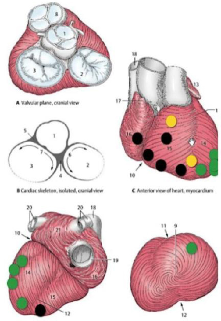
In our application, the epicardial electrode is required to be small and thin to minimize damage of fetal cardiac muscle during penetration. The threshold strength of the electrical stimulus to pace the heart can be minimized by selecting an appropriately sized electrode, thereby maximizing the very limited battery life. In preliminary experiments, we have observed that strained myocardial tissue had a higher threshold for pacing [13], so it is important to design the electrode so that it penetrates the epicardial and myocardial tissues cleanly. The epicardial connective tissue has a complex structure (Fig. 3) whose details vary in different regions of ventricular surfaces. Implantation through an intrauterine cannula provides little control and no direct visibility of the surface where the electrode must be implanted. We identified the mechanically relevant differences between regions and we built and tested an electrode that could be implanted successfully anywhere.
Figure 3.
Implantation location mapping of 17 in vivo implantation sites on 4 rabbits and 2 lamb fetuses during open chest or percutaneous surgery. Each dot represents an insertion attempt. Easy insertion is labeled green, strained insertion is yellow, and implant failure is shown in black. Failure was indicated by an inability to stimulate a contraction after electrode insertion.
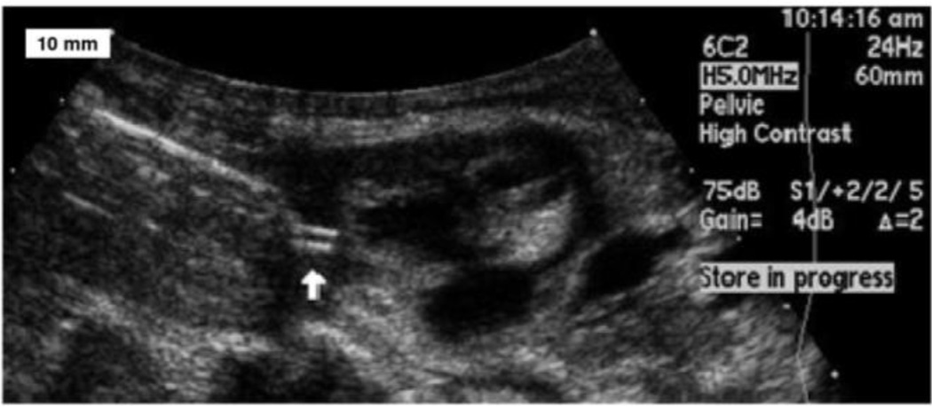
Our original sharpened helical tip was 4 mm in length, 8 turns, and with a 1.3 mm coil diameter. The tip was triangularly beveled (Franseen design) and made from 150 µm diameter annealed iridium wire with a Young’s modulus of about 400–600 GPa. We implanted it as illustrated in Fig. 2 in one percutaneous and three surgically exposed rabbit hearts and two transthoracic fetal sheep hearts (110–120 days gestation) under general anesthesia. Based on the results of the in vivo insertion tests, we systematically designed new electrodes and tested them by implantation in various regions of a cadaver pig heart. The improved electrode design was subsequently used in two percutaneous fetal sheep heart implantations.
Figure 2.
An ultrasound image shows the implantation of the helical electrode (white arrow) into myocardium. An epoxy reinforcing disk between the corkscrew electrode and the helical flexible lead is wedged into the end of thin wall plastic sheath. Under trans-uterine ultrasound guidance, the trocar and cannula are advanced until it abuts the fetal heart. The trocar is then removed and the plastic sheath assembly is inserted in its place. The fetal surgeon screws the electrode into the myocardium by rotating the sheath.
C. Results
As shown in Fig. 3, implantations of our original electrode design in vivo were successful on the left ventricle but unsuccessful on the right ventricle. Upon inspection, it was obvious that the epicardium on the right ventricle was relatively thin and its collagen bundles were oriented in straight, parallel lines, whereas the left ventricle had a thicker epicardium with heterogeneous distributions of fat and variously oriented collagen bundles. The right and left ventricular myocardial tissues have been reported to have differently layered structures [14], but once the epicardial layers were removed, we found that even a blunt needle could penetrate either ventricle.
The ability of an electrode to penetrate the epicardium cleanly depends on how well the sharpened tip cuts through the connective tissue. The fibrous collagen network is responsible for preventing tensile and shear failure at high strain. The elastin fibers are elastically deformable at low strain. Once the electrode is inserted against the connective tissue matrix, the elastin fibers are initially deformed, followed by the collagen fibers. The external work is temporarily stored in the strained membrane and will be fully released when the fibers are cut. This cutting and fracture mechanism was proposed by Doran et al [15]. This analysis implies that the electrode tip needs to cut through the connective tissue at low forces before remote plastic flow dissipates the insertion work and deforms the helical coil.
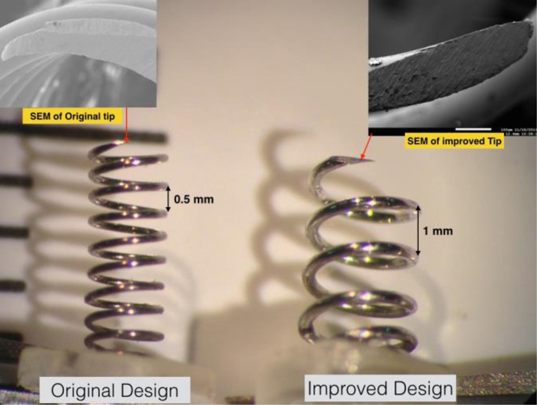
The sharpness and stiffness of the electrode play a critical role. We redesigned the new helix to use a heavier gauge wire (250 vs. 150 µm) and a steeper pitch (4 vs. 8 turns). We used a single bevel and a finer abrasive to achieve smoother and sharper edges (Fig. 4). The improved design could be inserted consistently into any region of cadaver pig heart.
Figure 4.
The redesigned electrode includes a thicker gauge wire and sharper edges, and has been successful in in vitro testing.
III. Recharging Methods and Physiologic Assessment
A. Strategy
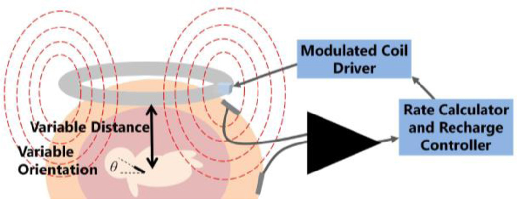
The fetal pacemaker will need to be repeatedly wirelessly recharged over 1 to 3 months. We have designed a transcutaneous RF magnetic coupling method to recharge the implant [16]. The strength of that coupling is highly variable due to movement of the fetus and the device within the uterus, as shown in Fig. 5, so the recharging process must be carefully monitored and controlled to be sure that it is proceeding to completion without overcharging or damaging the lithium cell.
Figure 5.
The closed loop recharging system includes software and hardware that monitor the induced current in the device and adjusts the field strength accordingly.
In order to monitor and control the cell and recharging process, we take advantage of the change in pacing rate with supply voltage, a technique used to decide when to replace the earliest cardiac pacemakers circa 1960, which were based on a relaxation oscillator circuit similar to what we have used in this device. As the cell's charge is drained, its voltage decreases, resulting in a small but detectable change in the rate of output pulses as the internal voltage drop in the transistor becomes a larger fraction of the supply voltage to the circuit. If the cell is being charged, the recharge current passing through the resistance in this circuit results in a voltage that effectively adds to the supply voltage for the oscillator. We use the relationship between output pulse rate and supply voltage to monitor charge level and recharging rate of the cell.
The changes in output rate are subtle and actual rates depend on component values that are somewhat variable, so a precise calibration curve of output rate vs. supply voltage is created during manufacture of each device. During use the cell voltage can be calculated from the pacing rate according to the stored calibration data in order to initiate or terminate charging. It is also important to control the charging current, which varies depending on the strength of coupling between the primary and secondary RF coils. Charging current can be determined from the internal resistance of the cell. Any charging current that is applied to the cell will produce an added voltage according to E = IR. For example, a 3 V lithium cell with an internal resistance of 100 ohms that is being recharged with 1 mA of current will actually generate 3.1 V. By accurately measuring the output pulse rate when the recharging field is turned on and again when it is turned off, this voltage change and the actual charging current can be computed. If that recharge current is excessive for the ratings of the cell, then the field strength produced by the external transmitter is automatically reduced until the rate change is consistent with the desired recharging current.
We have designed a recharging control system that picks up the pacemaker’s electrical artefact from surface electrodes using a custom designed electrical impulse detection amplifier that filters out the noise from the 6.78 MHz recharging field (Fig. 5). Pacing pulses are fed into software to calculate rate and a control algorithm monitors charge level and recharging rate of the battery. The current study aims to validate this system.
B. Methods
Validation of the recharging system includes in vitro and in vivo testing. Animal studies are underway to assess pacing performance and recharging in vivo. A fetal sheep model was chosen because it is similar in size to a human fetus at the gestational age that complete heart block may necessitate treatment. The fetal sheep has relatively little motion in utero and can tolerate surgery and instrumentation.
Testing in vitro involves submersing the pacemaker and recording output rate via electrodes in saline. Saline acts as a tissue model, replicating the electrical conduction of the stimulus artefact through tissue and simulating the tissue loading of the primary coil, which affects the efficiency of the Class E oscillator that drives the primary coil.
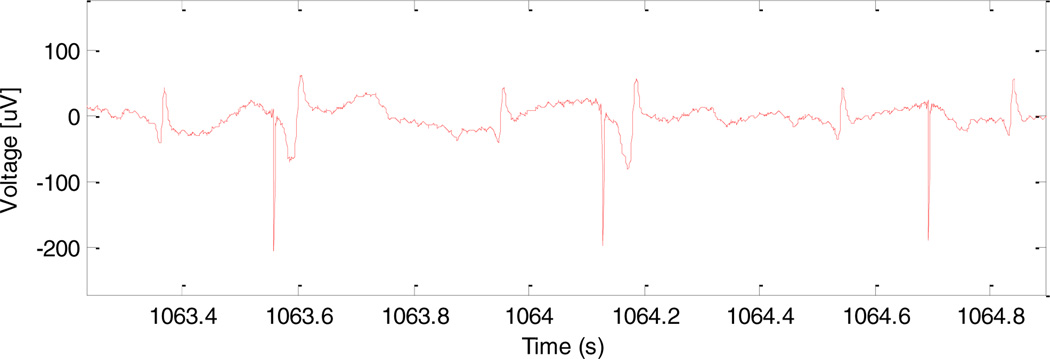
Validation of the physiological response to the pacemaker stimuli is performed in vivo in fetal sheep by analyzing the electrical signals recordable from the chest surface of the fetus. These are detected by stainless steel leads sutured to the chest and passed percutaneously to a pouch attached to the mother’s back. The signals are acquired and transmitted to a PC by the BioRadio Wireless Physiological Monitor (Great Lakes Neurotechnologies) and analyzed with Matlab (the MathWorks Inc). The recorded signals include the intrinsic ECG waveforms of the fetal sheep as well as the stimulus artefact caused by the pacemaker. Successful capture is determined by observation of an advancement in the timing of the QRS complex in close association with a stimulus artefact.
C. Results
Stimulus artefacts in vitro were successfully detected by the recharge controller, and rate and induced charging current were calculated. The pacemaker was successfully recharged, which was verified by determining the change in state of charge of the cell over time. When current was measured to be in excess of the required 1 mA recharging current, the current through the external RF coil was reduced by modulating the power supply voltage to its Class E driver.
Four separate in vivo studies have been performed so far on fetal sheep. A pacemaker was successfully implanted in the first fetal sheep and showed capture on ultrasound for five minutes, after which the prototype device failed. The fetus was allowed to continue gestation to term and then was euthanized and necropsied. The failure mechanism was not definitive, but could have included electrical failure or a fracture in the flexible lead. In the second sheep, two pacemaker implants were attempted, but failed due to the inability to advance the corkscrew electrode into the myocardium. Follow up investigation determined that the electrodes were not sharp enough to penetrate effectively through the epicardial connective tissue (as described above). In the third animal study, two pacemaker implants were again attempted, but failed due to an inability to reliably reach the outer surface of the myocardial wall for implantation. It was concluded that these difficulties were due to the lack of a pericardial effusion around the fetal heart that would normally be seen with hydrops fetalis. The lack of pericardial effusion results in an inadequate imaging plane to clearly define the pericardial space and epicardial surface and makes technical placement of the electrode at the epicardial surface much more challenging. Thus, in the fourth animal study, we created an artificial pericardial effusion using injected saline, which allowed for better visualization of the target and successful implantation of the device. After pacemaker deployment, a stimulus artefact could be recorded from surface electrodes on the maternal sheep abdomen, as will be done clinically with human patients. In addition, an ECG was recorded using three surface electrodes on the fetal sheep thorax which demonstrated ventricular capture at times when the refractory period of the ventricular myocardium was exceeded (as would be expected when the pacing rate is lower than the animal’s sinus rates) (Fig. 6).
Figure 6.
Electrical signals from fetal ECG leads. From left to right, the complexes reflect normal sinus rhythm (NSR), pacing capture (PC), NSR, PC, NSR, and a pacing artefact without capture followed by NSR.
D. Future Work: Safety Factor
In order to determine the relative safety factor of the delivered stimulus intensity, the minimal pacing interval after an intrinsic ventricular depolarization that results in ventricular capture can be assessed. This “relative refractory period” can be determined by analyzing a long fetal ECG recording and assessing whether ventricular capture was present with each pacing artefact depending on the time since the previous intrinsic QRS complex. A preliminary sample of this analysis is shown in Fig. 7. That interval can then be compared to a strength-interval curve that is normalized to the diastolic threshold, the minimal stimulus intensity necessary to capture the heart at maximally long stimulus intervals. The diastolic threshold would be considered a safety factor of one.
Figure 7.
This histogram of intervals between intrinsic QRS complexes and subsequent stimuli, along with their capture success or failure, shows the minimum interval is about 0.11 seconds.
IV. Conclusion
Preclinical studies have resulted in demonstration of a successful, minimally invasive surgical procedure and a reliable mechanical and electrical electrode-tissue interface. It has also been demonstrated that the implanted devices successfully capture the ventricular myocardium resulting in contraction of the heart muscle.
Because the micropacemaker pulse parameters (charge, pulse duration, and rate) are fixed by the selection of the component values during fabrication, the stimulus intensity is also fixed. Future work will include collecting data to better understand the safety factor of the stimulus, the amount of excess charge that is applied to the tissue above threshold. Information about the safety factor will allow changes to the design to be made for future devices to optimize power cell lifetime and device reliability. For instance, if these experiments suggest that the safety factor is too low, the pulse strength can be increased in subsequent test devices by changing component values; if too high, a longer recharge interval could be obtained by reducing stimulus charge.
Future work will also include in vivo demonstration of recharging ability over the required device lifetime. Several more implantations in fetal sheep are scheduled that will yield additional data about surgical success, mechanical robustness, and the ability to recharge.
Acknowledgments
This work was supported by the Wallace H. Coulter Foundation, the Southern California Clinical and Translational Science Institute, the Robert E. and May R. Wright Foundation, and the National Institutes of Health.
Contributor Information
Li Zhou, Medical Device Development Facility, Department of Biomedical Engineering, Viterbi School of Engineering, University of Southern California, Los Angeles, CA, USA.
Adriana N. Vest, Medical Device Development Facility, Department of Biomedical Engineering, Viterbi School of Engineering, University of Southern California, Los Angeles, CA, USA
Ramen H. Chmait, Department of Obstetrics and Gynecology, Keck School of Medicine, University of Southern California, Los Angeles, CA, USA
Yaniv Bar-Cohen, Division of Cardiology, Children's Hospital Los Angeles, Keck School of Medicine, University of Southern California, Los Angeles, CA, USA.
Jay Pruetz, Division of Cardiology, Children's Hospital Los Angeles, Keck School of Medicine, University of Southern California, Los Angeles, CA, USA.
Michael Silka, Division of Cardiology, Children's Hospital Los Angeles, Keck School of Medicine, University of Southern California, Los Angeles, CA, USA.
Kaihui Zheng, Medical Device Development Facility, Department of Biomedical Engineering, Viterbi School of Engineering, University of Southern California, Los Angeles, CA, USA.
Ray Peck, Medical Device Development Facility, Department of Biomedical Engineering, Viterbi School of Engineering, University of Southern California, Los Angeles, CA, USA.
Gerald E. Loeb, Medical Device Development Facility, Department of Biomedical Engineering, Viterbi School of Engineering, University of Southern California, Los Angeles, CA, USA.
References
- 1.Groves AM, et al. Outcome of isolated congenital complete heart block diagnosed in utero. Heart. 1996;75:190–194. doi: 10.1136/hrt.75.2.190. [DOI] [PMC free article] [PubMed] [Google Scholar]
- 2.Schmidt KG, et al. Perinatal outcome of fetal complete atrioventricular block: A multicenter experience. Journal of the American College of Cardiology. 1991;17:1360–1366. doi: 10.1016/s0735-1097(10)80148-2. [DOI] [PubMed] [Google Scholar]
- 3.Friedman DM, et al. Utility of Cardiac Monitoring in Fetuses at Risk for Congenital Heart Block. Circulation. 2008;117:485–493. doi: 10.1161/CIRCULATIONAHA.107.707661. [DOI] [PubMed] [Google Scholar]
- 4.Groves AM, et al. Therapeutic Trial of Sympathomimetics in Three Cases of Complete Heart Block in the Fetus. Circulation. 1995;92:3394–3396. doi: 10.1161/01.cir.92.12.3394. [DOI] [PubMed] [Google Scholar]
- 5.Friedman DM, et al. Evaluation of fetuses in a study of intravenous immunoglobulin as preventive therapy for congenital heart block: Results of a multicenter, prospective, open-label clinical trial. Arthritis & Rheumatism. 2010;62:1138–1146. doi: 10.1002/art.27308. [DOI] [PMC free article] [PubMed] [Google Scholar]
- 6.Pisoni CN, et al. Failure of intravenous immunoglobulin to prevent congenital heart block: Findings of a multicenter, prospective, observational study. Arthritis & Rheumatism. 2010;62:1147–1152. doi: 10.1002/art.27350. [DOI] [PubMed] [Google Scholar]
- 7.Robinson BV, et al. Use of terbutaline in the treatment of complete heart block in the fetus. Cardiol Young. 2001;11:683–686. doi: 10.1017/s1047951101001123. [DOI] [PubMed] [Google Scholar]
- 8.Walkinshaw SA, et al. In utero Pacing for Fetal Congenital Heart Block. Fetal Diagnosis and Therapy. 1994;9:183–185. doi: 10.1159/000263929. [DOI] [PubMed] [Google Scholar]
- 9.Assad RS, et al. New lead for in utero pacing for fetal congenital heart block. The Journal of Thoracic and Cardiovascular Surgery. 2003;126:300–302. doi: 10.1016/s0022-5223(03)00220-4. [DOI] [PubMed] [Google Scholar]
- 10.Carpenter RJ, Jr, et al. Fetal ventricular pacing for hydrops secondary to complete atrioventricular block. Journal of the American College of Cardiology. 1986;8:1434–1436. doi: 10.1016/s0735-1097(86)80319-9. [DOI] [PubMed] [Google Scholar]
- 11.Zhou L, et al. Engineering in Medicine and Biology Annual International Conference. San Diego: 2012. Percutaneously injectable fetal pacemaker: electrodes, mechanical design and implantation; p. 4. [DOI] [PMC free article] [PubMed] [Google Scholar]
- 12.Spotnitz HM. Surgical Implantation of Pacemakers and automatic defibrillators. In: Cohn LH, editor. Cardiac Surgery in the Adult. 4 ed. New York: McGraw-HIll; 2012. [Google Scholar]
- 13.Loeb GE, et al. Design and Testing of a Percutaneously Implantable Fetal Pacemaker. Annals of Biomedical Engineering. 2013;41:17–27. doi: 10.1007/s10439-012-0631-3. [DOI] [PMC free article] [PubMed] [Google Scholar]
- 14.LeGrice IJ, et al. Laminar structure of the heart: ventricular myocyte arrangement and connective tissue architecture in the dog. American Journal of Physiology-Heart and Circulatory Physiology. 1995;269:H571–H582. doi: 10.1152/ajpheart.1995.269.2.H571. [DOI] [PubMed] [Google Scholar]
- 15.Doran C, et al. A simplified model to determine the contribution of strain energy in the failure process of thin biological membranes during cutting. Strain. 2004;40:173–179. [Google Scholar]
- 16.Nicholson A, et al. Closed-Loop Recharging System for a Fetal Pacemaker. Biomedical Engineering Society Annual Meeting, Seattle. 2013 [Google Scholar]


