Abstract
The current Small Animal Radiation Research Platform (SARRP) is poor for localizing small soft tissue targets for irradiation or tumor models growing in a soft tissue environment. Therefore, an imaging method complementary to x-ray CT is required to localize the soft tissue target’s Center of Mass (CoM) to within 1 mm. In this paper, we report the development of an integrated x-ray/bioluminescence imaging/tomography (BLI/BLT) system to provide a pre-clinical, high resolution irradiation system. This system can be used to study radiation effects in small animals under the conebeam computed tomography (CBCT) imaging guidance by adding the bioluminescence imaging (BLI) system as a standalone system which can also be docked onto the SARRP. The proposed system integrates two robotic rotating stages and an x-ray source rated at maximum 130 kVp and having a small variable focal spot. A high performance and low noise CCD camera mounted in a light-tight housing along with an optical filter assembly is used for multi-wavelength BL tomography. A three-mirror arrangement is implemented to eliminate the need of rotating the CCD camera for acquiring multiple views. The mirror system is attached to a motorized stage to capture images in angles between 0–90° (for the standalone system). Camera and CBCT calibration are accomplished.
Keywords: x-ray, bioluminescent tomography, CBCT, small animal radiation research platform
1. INTRODUCTION
The detection of small soft tissue targets in small animals with non-invasive imaging has always been challenging. Current conventional imaging modalities include micro-magnetic resonance imaging (micro-MRI), high resolution ultrasound system, micro-positron emission tomography (micro-PET), micro-single photon emission computed tomography (micro-SPECT) and micro-computed tomography (micro-CT). We have employed on-board CBCT on our in-house small animal research platform [1] to aid target localization for pre-clinical radiation of small animals. The SARRP system is a portable robotic system which can deliver x-ray beams with high precision as small as 0.5 mm. The system comprises of a gantry with 360° range of motion from vertical and a robotic stage with rotational and translational motions to position the animal and facilitate sophisticated conformal beam therapy. Unlike most conventional pre-clinical irradiation devices that deliver radiation beams through single beams, SARRP can deliver the radiation over a conformal arc [1]. The SARRP is aimed to bridge the animals’ radiation research studies and to advance the human radiation treatment approaches. A similar system to the SARRP is developed in [2] for the micro-CT guided small animal robotic needle positioning (within 25 cm diameter bore) having mean targeting error of <200 µm. In this system there is no need to transport the animal from one workspace to another one which comforts the workflow of interventions. A new pre-clinical platform including a small animal microirradiator, a multimodal optical microscopy for cellular-level longitudinal imaging, and a laser-capture microdissection is presented for ex vivo tissues for transcriptomic profiling [3]. This work gives an insight on the potential quantitatively study of cellular and subcellular information of dynamic biological response of solid tumors to in vivo ionizing radiation.
There are numerous research works that developed x-ray systems and presented their calibration methods for performing CT imaging [4–6]. In [5] a simple method for CBCT calibration by abridging the seven-parameter to five-parameter problem resulting in less than 1% error is introduced. Gross et al. have developed a novel technique to perform the automatic calibration for the CBCT or flat-panel CTs when there is perfect calibration for a circular image acquisition orbit (360°) [6]. This is, however, an off-line procedure and the parameters need to be determined before application. In [7, 8] a research platform is designed for the purpose of conformal irradiation and treatment planning on small animals. In [7] a procedure called “dose painting” enables the SARRP to automatically paint complex dose shapes by rotating the robotic gantry from different angles. Radiation beams as small as 0.5 mm can be used to deliver radiation dose with high accuracy. Wong et al. have presented the proof of concept for the design and evaluation of the SARRP for the purpose of image-guidance, irradiation and treatment planning studies [8]. Other groups have developed similar small animal irradiation platforms [9–11]. One system employs a carbon nanotube field emission technology with the multi-pixel cathode array chip for micro-radiotherapy (micro-RT). The key advantages of the system are the high temporal resolution and the ability to electronically form any arbitrary shaped beams with varying radiation intensity distributions [9]. Another prototype micro-RT system has been developed with the multimodality imaging, treatment planning and conformal radiation therapy capabilities [10]. A radioactive Ir-192 source is used with resolution better than 2 mm. A number of machined tungsten collimators installed on a shielded cylindrical housing are used to form radiation beam portals. In [11], a variable aperture collimator consisting of a six trapezoidal brass blocks mounted on a rigid frame is designed for beam shaping of the micro-RT scanner and selectively irradiate the desired radiation target. This unit can robustly deliver radiation dose at high resolution with reasonable short exposure time.
It is challenging to use x-ray CBCT imaging to localize small targets in a low contrast, soft tissue environment; however, a complementary imaging methodology is needed. In this paper, we introduce a standalone research platform integrating an x-ray CBCT and optical tomography system to localize soft tissue targets. For the purpose of the CT imaging, we employ an x-ray source (Kevex PXS10-65W, Thermo Scientific Co., Waltham, MA, USA) with maximum operating energy of 130 kVp rated at 65W. A high speed detector panel is used to acquire projection images of a small animal placed on a motorized stage revolving between 0–360°. A computer-based control platform is used to control the motion of the stage. The optical imaging system is designed for dual-use: 1) it operates with the CBCT of the standalone system for BLI/BLT imaging to render image fusion unnecessary and eliminate the setup variability; 2) it can be docked onto the SARRP to provide BLI/BLT guidance. In order to operate the system in an unshielded room, three lead layers are used to reduce radiation exposure within acceptable limits. This paper is organized as follows: 1- The integration of the robotic controller system for operating the stage to acquire multi x-ray projection images and the optical images for tomography; 2- Radiation shielding; and 3- The process of calibrating the CCD camera with double light diffusion films.
2. ROBOTIC SYSTEM DESCRIPTION AND OPTICAL TOMOGRAPHY SET-UP
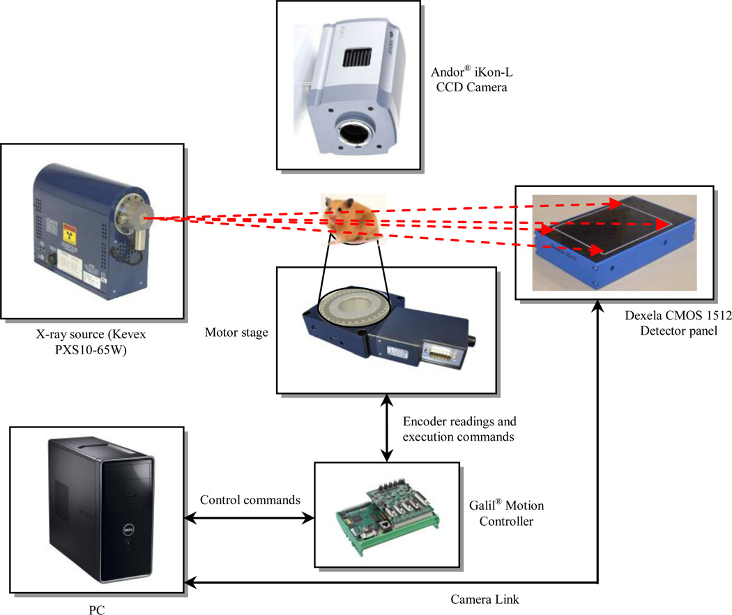
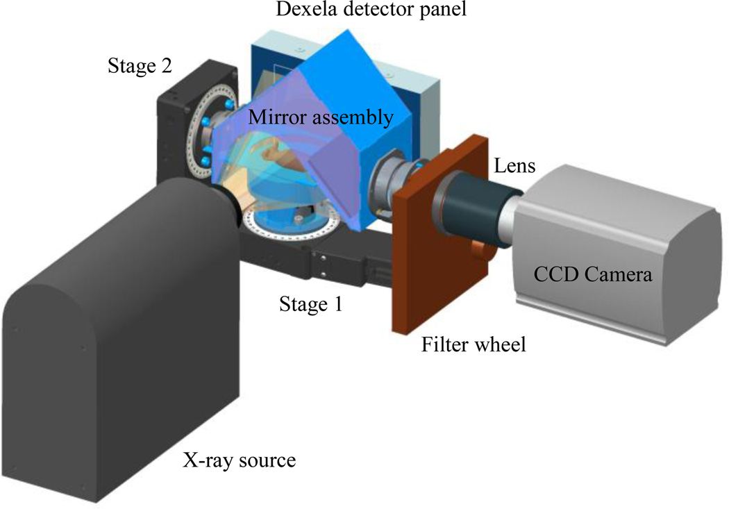
Figure 1 displays the standalone framework and the communication block diagram representing different components to facilitate the CBCT and optical imaging. A high resolution CMOS x-ray detector panel with 74.8 µm pixel pitch is used to provide the “near” micro-CT capabilities. Table 1 shows the CMOS detector panel specifications. The CMOS image sensor is supplied with two types of scintillators: 150 µm thick Gadolinium Oxysulphide (GdOS) on the aluminum substrate and 600 µm thick CsI on the amorphous carbon substrate. The sustained frame rate for 1×1 binning of the 1944 × 1536 pixels using the Camera Link is 26 Hz. The precise robotic stage from URS100BCC DC motor (Newport Corp., CA, USA) is employed. This backlash-free stage has a precision of 8,000 counts/rev with 0.0005° resolution. Integrating the rotary encoder with index pulse provides high-torque for rotating the stage up to 80°/s [12]. 3D CAD model of the CBCT/BLI structure is shown in Fig. 2. The camera is placed perpendicular to the source-panel path displaced from the x-ray beam.
Figure 1.
Communication and schematic block diagram of the automatic motorized platform for acquiring the CBCT and BL images.
Table 1.
Specifications of the 1512 CMOS x-ray detector panel.
| 1512 CMOS x-ray detector 15 × 12 cm [13] | |
|---|---|
| Pixel size: 74.8 µm | 14 bit digital output |
| Sensitive area: 145.4 mm × 114.9 mm | Scintillator options: CsI 150 µm, CsI 600 µm, Gadox |
| 1944 × 1536 pixels | Sensor type: CMOS active pixel sensor |
| Binning 1×1 to 4×4 | Camera Link |
Figure 2.
3D CAD model of the CBCT/BLI prototype.
For acquiring a CBCT image from an x-ray source, the phantom/animal sitting on the turn-table is rotated by 2π using a controlled robotic system to ensure consistent and precise operation. The platform can accommodate imaging of a few mice at the same time. A C++ software program installed on a 64-bit Win7 platform in VS2010 is used to actuate the motor stages with various speeds and torques. Each channel of the controller is capable of reading the encoders’ data and uses them as the feedback signals to a PID controller with tunable gains (proportional, integral, and derivative gains as KP, KI, KD). For each channel assigned to the mirror and turn-table stages, separate PID gain is adjusted independently. The C++ code is designed to the functions of the controller and detector panel to automatically revolving the stage, while acquiring and recording multi projection images. This could be operated in a fast mode taking less than one minute for CBCT imaging routine while still preserving high image quality (i.e., 1×1 binning image).
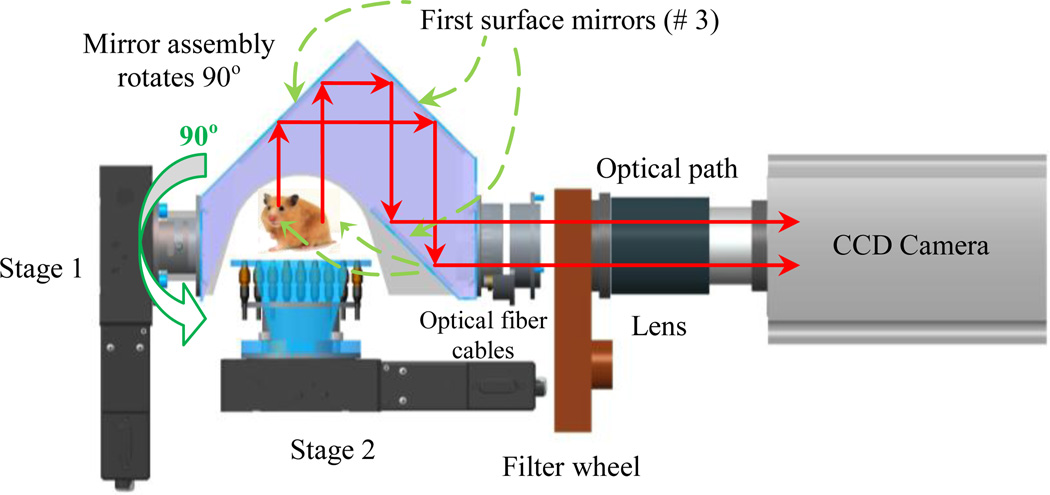
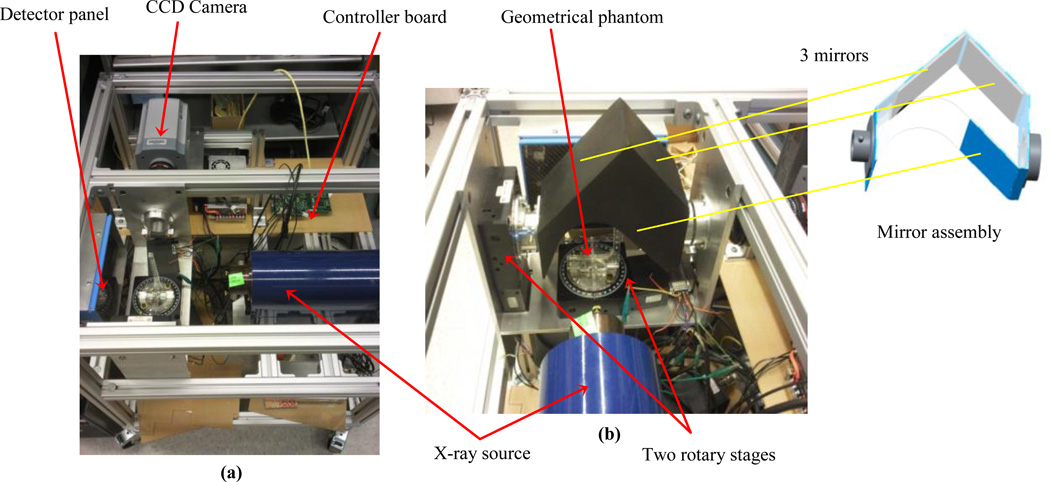
The optical imaging system is composed of a CCD camera (Andor® iKon-L, Belfast, UK), a filter wheel (HSFW, Optec Inc., Michigan, USA), a lens, and a mirror assembly to capture the light in a completely dark environment. The mirror assembly includes three first-surface mirrors (shown in Figures 2, 4, and 5). The distance from the camera lens to the iso-center is 38 cm.
Figure 4.
Optical tomography arrangement.
Figure 5.
Current implementation of the x-ray/BLI system with a geometrical phantom and the mirror assembly configuration: a) top view, b) side view.
The main focus of the design is that the integrated x-ray CT and BL imaging system facilitates the operation of both subsystems without the need to reposition the animal.
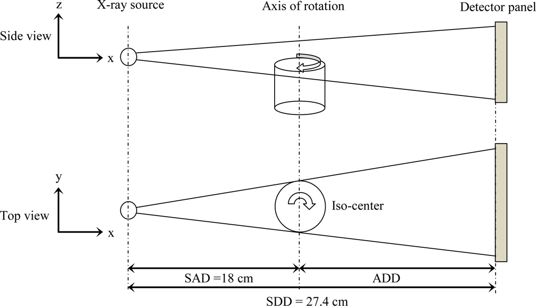
The principle of the CBCT imaging guidance is illustrated in Fig. 3. The animal is horizontally rotated between the x-ray source and a high speed, low noise digital detector panel. The detector panel is located at the source-to-detector distance (SDD) of 27.4 cm. The position of the object is determined by source-to-axis distance (SAD) of 18.0 cm. The x-ray system can operate at the maximum power 65 Watts for 130 kVp x-rays with the focal spot size of 56µ. Typically, lower kVp x-rays are used to achieve better radiographic contrast. After specifying and calibrating the abovementioned distances, more corrections may be required for the system due to the manufacturing or installation misalignments.
Figure 3.
Principle of the CBCT imaging; side and top views.
The optical tomography set-up is illustrated in Fig. 4. This arrangement is comprised of a three mirror assembly, filter wheel, lens and a high sensitive and low noise CCD camera. The CCD camera is used to acquire images at different wavelengths and different directions from homogeneous or heterogeneous tissue-simulating phantom or animals. The mirror assembly is connected to a rotary stage which can be rotated between 0–90°. The novel mirror system allows the acquisition of BL images from 0 to 90° without the need to rotate the camera. The mouse turn-table has nine holes for the insertion of optical fiber cables to illuminate the mouse for the determination of its internal optical properties by means of diffusion optical tomography (DOT). In Fig. 5 the current implementation of the x-ray/BLI system is shown.
The filter wheel in front of the camera is capable of holding up to 5 filters (5 cm diameter) and can be positioned by the computer-based control. Using the same CCD camera, transmission measurement can be performed at one or more angles using the fiber-optic white light source. The filters allow transmission measurements at the same wavelengths of the BL source for the purpose of DOT to improve BLT reconstruction [14]. These filters can be exchanged to evaluate the emission spectra of the luminescence which will be useful for fluorescence tomography (FL) using the same system.
In total, x-ray CT image offers the external boundary and major internal soft tissues of the animal. Diffusion optical tomography is used to derive the internal optical properties of the animal. These subsystems provide a priori information to improve the reconstruction of BL tomography from the BLI images.
3. IMPLEMENTATION OF THE RADIATION SHIELDING
The final configuration for mounting the CCD camera and the x-ray imaging system is shown in Figures 2 and 5. The camera and x-ray are installed in right angle with respect to each other while still retaining a compact form. In order to avert radiation to the surrounding environment, we have implemented three layers of shielding; primary, secondary and third (whole-unit) protective shields as depicted in Fig. 6. The primary shield consists of 1/4" thick lead to cover the x-ray source entirely and minimize leakage exposure to the surrounding environment and the CCD camera. The secondary shield is made of sandwich plates of 1/16" stainless steel, 1/8" lead and 1/16" stainless steel to provide an enclosure that covers the turn-table, mouse, and mirror assembly and block the radiation exposure to the high sensitive CCD camera. The inside part of the secondary shield (enclosure) needs to be completely darken to avoid any reflection that may interfere with optical imaging. The third shield is also made of sandwich plates of 1/16" stainless steel, 1/8" lead and 1/16" stainless steel. The third shield is easily attachable and detachable to allow needed work space. Due to weight of shield, we have added four heavy-duty casters to ease moving to other sites.
Figure 6.
System protective shields: primary, secondary, and third (whole-unit) protection shields.
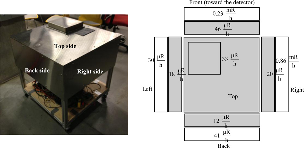
After installing the protective shield, the x-ray system is turned on to run at the highest power and x-ray energy. Results of radiation leakage measurements made with a survey meter are shown in Fig. 7. The leakage radiation is much lower than the 2 mR/hr regulatory limit for authorized user. The system is therefore safe for operation without having any additional protective enclosures. In order to avoid overheating of the electronics, a cooling fan is employed for the controller board while a water cooling system is used to maintain the operation of the CCD camera at the specified −100°C temperature. Finally, a small removing cap is installed on top of the unit to allow placement of the animal and cleaning.
Figure 7.
The installed overall stainless steel/lead shield (left) and radiation survey at 100 kVp, 500 µA, (gray: shielded and white: unshielded) (right).
4. CAMERA CALIBRATION PROCEDURE
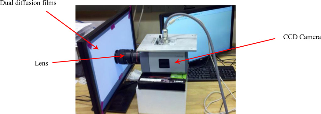
The CCD camera needs to be properly calibrated to support optical tomography. A calibration procedure is devised which require a computer monitor, double light diffusion films, Nikon lens, and CCD camera. All experiment must be performed inside a completely dark enclosure. Figure 8 shows the experimental set-up before covering with a dark box.
Figure 8.
Experimental set-up including CCD camera, dual diffusion films, and lens before covering with a dark box.
Flat field correction of the CCD camera is performed to correct the vignetting artifact associated with the Nikon F/2.8 lens. A brand new computer monitor with two layers of diffuse films attached on the surface provides the necessary uniform light source. Light is captured with the CCD camera with its lens positioned against the outer layer film. The monitor is tuned to emit green light with the proper brightness that does not cause CCD saturation. The camera is set with following parameters: exposure time = 0.4 sec; readout speed = 3MHz; gain = 1×; 1×1 binning. An auto shutter is employed. The corrected flood image is obtained by subtracting the background and readout noise from the raw flood image. The final correction map is derived as the ratio of the mean signal intensity over the corrected flood image to the signal intensity of individual pixels.
The followings are details warranted attention during camera setup:
1- In the “permanently open” shutter mode, the CCD read out could cause non-uniform exposure due to the order of data readout. The image was bright at the top and dark at the bottom. This was eliminated by using “fully auto” shutter mode; 2- Read out speed was limited to within 3 MHz. 5 MHz is only for focus adjustment and its use produced artifacts in the acquired data; 3- Dark current is dependent on exposure time and temperature; 4- A diagonal pattern was seen when blue light was used. This is due to the back thinning process during manufacturing which is wavelength dependent and usually appears at short wavelengths. It was not seen when green light was used. This pattern can also be eliminated using flat-field correction; 5- The non-uniformity is about 15%. The dark current plus readout noise was about 0.5% of signal with our current setup.
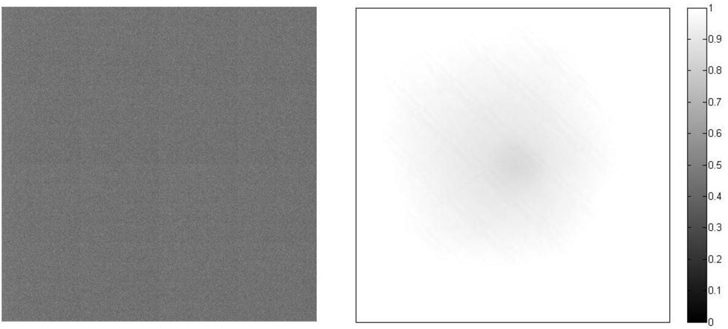
A flood image is shown in Fig. 9 (a) and profiles are shown in Figures 9 (b, c) with the average dark image shown in Fig. 10. More accurate flat field correction will be performed with an integrating sphere in the future.
Figure 9.
Averaged bright image of the uniform light source (a), profiles along the middle horizontal and vertical lines (b), (c).
Figure 10.
Averaged dark image: Pixel intensity is around 300, while the bright image at the same setup is 5.5×10⁴ (left), Flat field correction matrix (right).
CONCLUSIONS
An integrated x-ray/bioluminescence system for pre-clinical research of disease process and treatment response with small animals is presented in this paper. The novel design supports automatic CBCT with variable rotating speeds and image acquisition. The system comprises of two sets of rotary stages with ultra-high resolution and high torque for rotating the turn-table and the mirror assembly. A high speed, low noise and high sensitivity detector is utilized for online projection image acquisition. C++ programming codes are developed to operate the hardware devices and actuate the stages. Bioluminescence imaging is employed to detect small targets that would be difficult with x-ray CBCT. The designed standalone system is expected to be capable of localizing the target’s center of mass to within 1 mm. Three different lead shielding layers were installed to avoid radiation damage of the sensitive CCD camera as well as to limit the exposure to the surrounding environment for safe operation. Finally, the process of the camera calibration using dual diffusion films was described. Phantom studies and validation of the BLT algorithm are ongoing and will be accomplished. Clinical tests on animal will then follow as the final phase of the research.
ACKNOWLEDGEMENT
This work is supported by the NIH grant R01 CA158100-01.
REFERENCES
- 1.Matinfar M, Gray O, Iordachita I, Kennedy C, Ford E, Wong J, Taylor R, Kazanzides P. Small Animal Radiation Research Platform: Imaging Mechanics, Control, and Calibration. Med. Imag. Comput. Assist. Interv. 2007;10((Pt. 2)):926–934. doi: 10.1007/978-3-540-75759-7_112. [DOI] [PubMed] [Google Scholar]
- 2.Bax JS, Waring CS, Sherebrin S, Stapleton S, Hudson TJ, Jaffray DA, Lacefield JC, Fenster A. 3D Image-guided Robotic Needle Positioning System for Small Animal Interventions. Med. Phys. 2013;40(1):15. doi: 10.1118/1.4771958. 011909. [DOI] [PubMed] [Google Scholar]
- 3.Maeda A, Leung MK, Conroy L, Chen Y, Bu J, Lindsay PE, Mintzberg S, Virtanen C, Tsao J, Winegarden NA, Wang Y, Morikawa L, Vitkin IA, Jaffray DA, Hill RP, DaCosta RS, Bogyo M. In Vivo Optical Imaging of Tumor and Microvascular Response to Ionizing Radiation. PLoS One. 2012;7(8):e42133. doi: 10.1371/journal.pone.0042133. [DOI] [PMC free article] [PubMed] [Google Scholar]
- 4.Matinfar M, Ford E, Iordachita I, Wong J, Kazanzides P. Image-guided Small Animal Radiation Research Platform: Calibration of Treatment Beam Alignment. Phys. Med. and Bio. 2009;54:891–905. doi: 10.1088/0031-9155/54/4/005. [DOI] [PMC free article] [PubMed] [Google Scholar]
- 5.Yang K, Kwan ALC, Miller DF, Boone JM. A Geometric Calibration Method for Cone Beam CT Systems. Med. Phys. 2006;33(6):1695–1706. doi: 10.1118/1.2198187. [DOI] [PMC free article] [PubMed] [Google Scholar]
- 6.Gross D, Heil U, Schulze R, Schoemer E, Schwanecke U. Auto Calibration of a Cone-Beam CT. Med. Phys. 2012;39(10):5959–5970. doi: 10.1118/1.4739247. [DOI] [PubMed] [Google Scholar]
- 7.Matinfar M, Iyer S, Ford E, Wong J, Kazanzides P. Image Guided Complex Does Delivery for Small Animal Radiotherapy. 2009 IEEE Int. Symp. On Biomed. Imag.: From Nano to Micro; USA; Boston, MA. 2009. Jun-Jul. [Google Scholar]
- 8.Wong J, Armour E, Kazanzides P, Iordachita I, Tryggestad E, Deng H, Matinfar M, Kennedy C, Liu Z, Chan T, Gray O, Verhaegen F, McNutt T, Ford E, DeVeese T. A High Resolution Small Animal Radiation Research Platform (SARRP) with X-ray Tomographic Guidance Capabilities. Int. J. Radiat. Oncol. Biol. Phys. 2008;71(5):1591–1599. doi: 10.1016/j.ijrobp.2008.04.025. [DOI] [PMC free article] [PubMed] [Google Scholar]
- 9.Wang S, Liu Z, Sultana S, Schreiber E, Zhou O, Chang S. A Novel High Resolution Micro-Radiotherapy System for Small Animal Irradiation for Cancer Research. BioFactors. 2007;30:265–270. doi: 10.1002/biof.5520300408. [DOI] [PubMed] [Google Scholar]
- 10.Stojadinovic S, Low DA, Hope AJ, Vicic M, Deasy JO, Cui J, Khullar D, Parikh PJ, Malinowski KT, Izaguirre EW, Mutic S, Grigsby PW. MicroRT-small Animal Conformal Irradiator. Med. Phys. 2007;34(12):4706–4716. doi: 10.1118/1.2799887. [DOI] [PubMed] [Google Scholar]
- 11.Graves EE, Zhou H, Chatterjee R, Keall PJ, Gambhir SS, Contag CH, Boyer AL. Design and Evaluation of a Variable Aperture Collimator for Conformal Radiotherapy of Small Animals Using a microCT Scanner. J. of Med. Phys. 2007;34(11):4359–4367. doi: 10.1118/1.2789498. [DOI] [PubMed] [Google Scholar]
- 12. http://assets.newport.com/webDocuments-EN/images/URS-B_Data_Sheet_MC.pdf. [Google Scholar]
- 13. http://www.dexela.com/documents/1512_data_sheet.pdf. [Google Scholar]
- 14.Lin Y, Barber WC, Iwanczk JS, Nygard E, Malakov N, Hartsough NE, Gandhi T, Roeck WW, Nalcioglu O, Gulsen G. Dual-modality Molecular Imaging for Small Animals Using Fluorescence and X-ray Computed Tomography. Proc. of the SPIE, Prog. Biomed. Opt. Imag., Molec. Imag. II. 2009;7370 [Google Scholar]


