Abstract
In vivo biomedical research is pivotal to translate in vitro findings into clinical advances. Small academic institutions with limited resources find it virtually impossible to build and maintain typical rodent facilities for research. Zebrafish research has been demonstrated to be a valuable alternative for in vivo research in pharmacology, physiology, development and genetic studies. This article demonstrates that a functional zebrafish facility can be built in an easy and affordable manner. We demonstrate that such a facility could be built in about one working day with minimal tools and expertise. The cost of the 27 1.8 L fish tank zebrafish facility constructed in this study was approximately $1,500. We estimate that the maintenance of an initial working 150 fish colony for 3 months is $1,000. This project involved students, who were introduced to aquaculturing of zebrafish for research proposes.
Keywords: Basic Protocols, Issue 93, Zebrafish, in vivo, novice, practical, construction, affordable, aquarium, aquaculture, fish breeder racks.
Introduction
In vivo models are essential in conducting comprehensive biomedical research since they allow in vitro research to be translated at the system and organismal level. For example, research with small mammals, namely rodents, has been proven necessary in the development of drugs and in the improvement of available drugs. However, the complexity (financially and logistically) might make it virtually impossible to build and maintain rodent facilities for experimentation proposes at small research academic institutions. Nonetheless, in vivo research can be performed using other animal species that require less elaborate logistics. Zebrafish (Danio rerio) have been successfully used as an in vivo model to study genetics, development, pathophysiology, and pharmacology1,2,10,11,12. The facilities required to house zebrafish for experimentation are relatively simple and significantly less expensive when compared to rodent facilities. Kim et al.3 have recently described in detail an 80 tank zebrafish housing system that can be built for approximately $1,500, which includes both parts and labor costs. This stands in stark contrast to the nearly $8,500 that would be required to purchase a ready-made, 80 tank system from any number of commercial suppliers. However, the description given by Kim et al. may be complicated and difficult to follow for novices of fish research. We believe that a zebrafish facility can be constructed in simplified manner for an investment of $1,500.
The establishment of an in vivo facility at small academic institutions provides their faculties an additional tool with which to produce more powerful and thorough research. In vitro data supported by in vivo results generally produce more comprehensive biomedical research than data obtained using only in vitro approaches. Therefore, the implementation of an in vivo research facility will significantly enhance the institution success in its overall research endeavors (student exposure to research, publications, communications, pursuit of external funding, etc.).
The construction of a Zebrafish facility like the one described in this study is ideal for research academic institutions with limited facilities (or institutions without in vivo research facilities) during constricting financial times.
Protocol
NOTE: These protocols follow the guidelines of IACUC of Presbyterian College.
1. Acquire Materials Listed in Table 1.
2. Assemble the 5 Shelf Chrome According to the Manufacturer’s Instructions. This will be used to House the Facility.
3. Construct the water reservoir and filtration system (Figures 1A and 2).
Using Figure 1A as a guide, layout the 18 gallon bucket, pump, filters and UV lamp to determine final installation location and size.
Once parts are laid out, measure and cut the ¾” PVC pipe to the length needed for assembly. Vary the lengths of all pipes according to specific space needs and limitations.
- Assemble the pipes and fittings as laid out previously using the PVC primer and cement, see below (3.3.2 and 3.3.3).
- Sand the cut edges of the pipe with sandpaper until they are smooth to the touch and there is no debris.
- Prime the outside of the pipe and the inside of the fitting with the purchased PVC primer with the included swab from the PVC primer.
- Cement the pipe and fitting together by applying the PVC cement to the outside of the pipe using the included swab. Repeat for all steps that need PVC cementing.
- Place the 18 gallon bucket to one side of the shelf construction.
- Install a bulkhead connector in the side of the reservoir tank.
- Attach a ¾” PVC pipe to the bulkhead.
- Attach the other end of the ¾” pipe to the pump inlet using a ¾” threaded make fitting.
- Connect the filters to the pump using two 90 degree elbows and ¾” PVC pipe.
- Use one paper filter followed by one activated carbon filters in order to filter out debris and reduce chlorine and chemical levels in the water.
- Connect the UV lamp to the filters according to the manufacturer’s instructions.
Attach the pump and filter system to the top side of the first shelf of the rack using wire ties. Vary the order of the assembly and attachment according to the size and layout of the shelf/rack chosen.
Add 1 bioball per gallon of water to the water reservoir once the pump and filter system are assembled and attached to the shelf.
4. Construct the main supply line (Figures 1B and 2).
Measure and cut a piece of ¾” PVC pipe to connect the UV lamp to the main supply
- Use a ¾” PVC tee to start the main supply line by connecting the tee to the ¾” PVC exhaust coming from the UV filter. .
- Add an on-off valve to the bottom of the PVC tee to serve as a drain for maintenance flushing of the system.
- Start the main supply line from the top of the ¾” PVC tee by measuring and cutting ¾” PVC pipe to desired length to provide feed pipes for each of the shelves on the rack.
- Install ¾” PVC tees for the horizontal lines that will enter each shelf of the rack.
- Optionally (and suggested), add a ¾” on-off valve for each shelf supply line to allow for isolation of each shelf and a modular design of the system.
Use a ¾” PVC pipe as a pressure reducing line on the top shelf. If this line runs on the back of the shelf, use this shelf for storage. End the pressure reducing line in the main exhaust line (Figure 1B) with a ¾” on-off valve.
Once the above steps have been completed, prime and cement the PVC pipe together as previously done when constructing the reservoir and filtration system.
5. Construct the main exhaust line (Figures 1C and 2).
Run the vertical length of the main exhaust line to the other side of the rack from the main supply line. Use a 2” PVC pipe for this vertical line to receive the main supply line at the top and drain lines from the fish tanks from each shelf.
Cut the pieces of 2” PVC pipe for the vertical main exhaust line and use 2” PVC tees to receive the fish tank drain lines from each shelf. End the main exhaust line in the stock tank to expel the recycled water over a sponge filter.
Cut a one inch opening the entire length of the 2” PVC pipe pieces and attach to vertical main exhaust line with PVC tees for the horizontal drain lines from the fish tanks.
Cap the 2” horizontal drain lines with a 2” PVC cap.
Prime and cement the pieces using the necessary fittings (connectors, nipples or elbows).
6. Construct the fish tanks (Figure 3).
With the drill, cut a 1 1/8” hole at the back of the fish tank 1” below the upper edge with a hole saw.
Slide a threaded ¾” PVC male adapter (with a #18 O ring attached) through the hole (from the inside of the tank to the outside).
Attach and tighten a 90 degree 3/4' threaded PVC elbow to the male adapter to create the fish tank exhaust pipe. Add a piece of fine mesh before screwing the holding nut to prevent zebrafish going through the exhaust system.
Place the fish tank with its exhaust pipe ending into the open space of the draining line behind the tanks
7. Starting the water system
In several containers, such as the one used for the reservoir, measure three times the amount of water contained within the system. Let this water stand at room temperature for conditioning for 48 hr.
- Add water to the system and let it circulate for a minimum of 3 days.
- Change the water in the system vigorously throughout the initial 3 days of circulation in order to rid the system of contaminants that reside within the pipes.
Add starter zebrafish and allow the nitrogen cycle to get established. Normalize pH to a consistent 7. Keep seven zebrafish per 1.8 L, and feed them twice daily during week days and once daily during weekends as suggested by Linbo4 and McNabb6.
Monitor the nitrate (<75 mg/L), nitrite (<10 mg/L), and ammonium (0 mg/L) daily during the first week after adding fish, and twice weekly once desired levels have been maintained with regular water changes.
Representative Results
Construction of the Pump and Flters System Once the rack is assembled and set up the first step is to build the pump and filter system. The filters are connected to the system pump and are located above the bottom level of the first shelf, which allows for easy filter maintenance and replacement. Similarly, the UV lamp is connected with PVC pipe to the filter and held in place with plastic wire ties to allow for easy replacement of the UV lamp as needed (Figure 4A). Immediately following the pump a paper filter, activated carbon filter, and a UV lamp are installed via PVC pipe. Bioballs are added to the tank to provide surface for the growth of bacteria, which converts toxic ammonia waste to nitrates. One bioball per gallon of water in the system is sufficient area to allow bacterial growth. The lid of the plastic reservoir can be fitted so that in case of overflow the bioballs will remain in the reservoir and chances of contamination are minimized. Even though an overflow event is very unlikely, a draining system (adding a pipe drain at the top of the reservoir) is an easy addition that can be made to the system.
Construction of the Main Supply LIne The second step is to assemble the main water supply line that will feed every compartment that will contain the zebrafish tanks (Figure 4B). This line is connected to the UV lamp with a piece of PVC pipe. This line runs vertically and laterally to the rack through a PVC tee. The bottom end of the tee is used to connect a piece of PVC pipe that will serve as a drain valve for the whole system.
The main lines that feed the tanks run horizontally to four compartments: top of the second shelf, top of the third shelf, top of the third shelf, and bottom of the fifth shelf. Since the top of the second, third and fourth shelf lines provide water to the fish tanks they run at the midline of the shelves. Each of these lines have individual on-off valves, which allows the control of individual compartments.
A 9 port irrigation manifold is attached to the end of the horizontal lines, and these irrigators supply water to the fish tanks through flexible ¼” tubing (Figure 4B). Every port of the irrigation manifold has a built in on-off valve. In addition, an on-off valve is placed at the end of the tubing attached to each port, near the fish tank entrance, for easy access and water flow control. The tubing will be inserted into the tank by a hole drilled into the lid. This will aid in keeping the tubing firmly inserted into the tank.
The line that runs on the top of the fifth shelf is used as a pressure reliever and it is controlled with an individual on-off valve. It is recommended to have this line run at the back of the fifth shelf so that this area can be used for storage. Since the main line runs at the midline of the side of the rack, it is brought to the back using a PVC elbow and a piece of PVC pipe, and then it runs longitudinally (horizontal) as the pressure reliever line using another PVC elbow and a piece of PVC pipe. The pressure reliever line ends in the main exhaust line that runs vertically at the other side of the racks and ends into the water reservoir (this exhaust line is made of 2” PVC pipe, see below).
Construction of the Main Exhaust LIne The third step is to assemble the exhaust system, which runs laterally to the rack, at the side where the water reservoir is placed (Figure 4C). This system is built using 2” PVC pipe and collects the water that comes from the pressure reliever line, and from the fish tank draining (see fish tank construction below). The main exhaust line runs vertically, connecting the pressure reliever line on the top of the rack and ending into the water reservoir. Also, the main exhaust line receives the drain from the fish tanks through horizontal 2” PVC pipes that connect to the main exhaust line via PVC tees. These horizontal drain pipes have a 1' longitudinal cut to receive the drain water from the fish tanks (see below). These horizontal drain lines run at the back and on the bottom parts of the shelves and have a minor incline that allows the drained water to run to the main exhaust line by gravity. Sponge filter pads are added to the horizontal drain lines so that the fish tank drain water falls on the sponges and filters out debris. A whole assembled system is pictured in Figure 5.
Construction of Fish Tanks A representative fish tank is shown in Figure 6. The end of the fish tank drain line is placed into the horizontal drain line (see above section on exhaust line). A wire mesh is inserted into the drain line in the fish tank to prevent the zebrafish from swimming out of the tank. These particular tanks have lids that prevent the fish from escaping and also minimize contamination opportunities. If overflow occurs tank lids will prevent fish from falling to the floor. Tanks with lids are ideal but if a system is built which contains tanks without lids then a small hole may be drilled near the top of the tank. This will allow water to escape while prevent fish from escaping.
Functioning A zebrafish colony could be maintained by available and established protocols described elsewhere3-6. Briefly, our facility allows the system pump to circulate the system volume approximately 75 times per hr, by adjusting the flow rate for each adult (or larval fish tank) at approximately 85 ml/min (or 45 ml/min for larval fish tank). Water quality is maintained by active biological filtration and small-scale water changes (~5% of the system volume) as needed. Daily monitoring of pH, conductivity, dissolved oxygen (DO) levels, and temperature are necessary to keep conditions consistent. Kits are commercially available to measure pH and DO levels. Conductivity meters are also available for purchase. In order to test these variables daily, remove 250 ml of water from the reservoir and perform analysis. The pH level should be maintained at 7.2, DO should be less than 6 mg, and conductivity between 500 μS and 1,300 μS. (SOURCE HERE) Temperature must be maintained at 28.5 °C. Regular system maintenance (3 - 4 weeks) includes an approximate 30% water change and the cleaning and replacement of filter pads and charcoal.
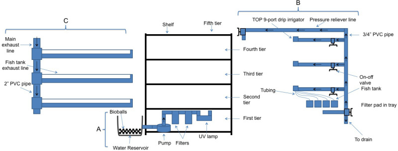 Figure 1: Three major components of a zebrafish facility. A. The pump and filters system are located at the bottom part of the shelf (first shelf) and connect the water stock tank with the major supply line. B. The major supply line derives from the UV lamp and supplies water to the three upper shelves that contain the fish tanks. Note that every shelf compartment is supplied independently and can be individually controlled (on or off) by means of a valve. This main line also has the main draining valve at the bottom end, and at the upper end continues as a pressure reliever line that ends into the main exhaust line. C. The main exhaust line receives water from the pressure reliever line and from the different fish tank compartments and ends into the water stock tanks. Note that every shelf has a fish tank exhaust line which are PVC pipes and are longitudinally open to receive water for individual fish tanks. These lines are slightly inclined to allow water to run by gravity to the main exhaust line. Please click here to view a larger version of this figure.
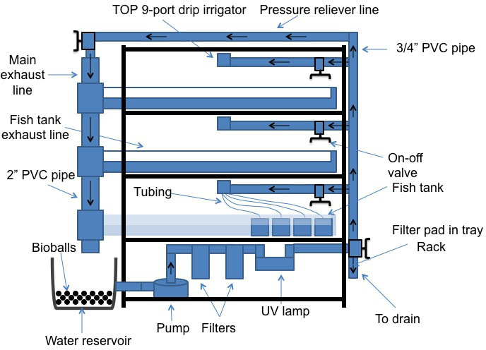 Figure 2:Three major components of a zebrafish facility assembled and readily functional. Note that the water stock tank already has bioballs. The water from the main exhaust line will fall on a sponge filter placed on mesh above the water level (for clarity this is not depicted in the figure). Note that for clarity the second shelf has only some fish tanks depicted, the irrigator shown has only 4 supply tubes, and the fish tank exhaust line is transparent. Every shelf of the rack can hold nine 1 L fish tanks and have a 9 port irrigator.
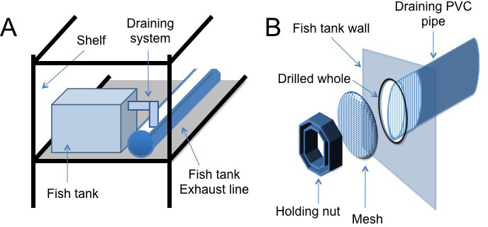 Figure 3:Fish tank unit. The fish tank is acquired in a regular pet store and it has a 2 L capacity. A. The fish tank draining system is constructed by drilling a 1 1/8” hole in the back side of the tank, then 3/4” PVC pipe pieces are placed in an inverted “L” shape using a 3/4” PVC elbow. This draining system will fall into the open side of the fish tank exhaust lines located at the back of the fish tanks. B. Image depicting the installation of a mesh into the fish tank draining system. The mesh prevents the zebrafish from being drained to the exhaust lines.
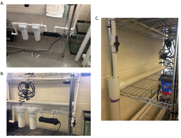 Figure 4:Individual parts construction. A. The three filter and pump system is on the bottom rack of the system. The pump is connected to three mechanical filters followed by a UV filter to eliminate contaminants from the system water. B. The horizontal supply line ends in a 9 port irrigation manifold, which will supply fresh water and oxygen to each tank. The supply line to each shelf has an on-off valve that can be used to stop water to each shelf for cleaning and quarantine purposes. C. The fish tank exhaust line empties into the main exhaust line to reenter circulation. The pressure relief line also empties into the main exhaust line.
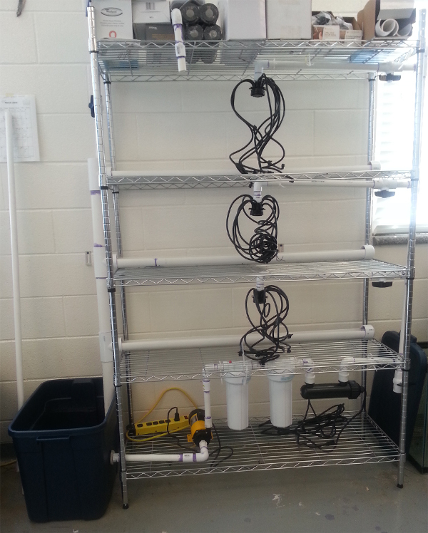 Figure 5: Completed system. The completed system contains a pump and filters system, a main vertical supply line, a horizontal supply line for each shelf, a tank exhaust line, a pressure relief line, and a main exhaust line for a contained circulation system.
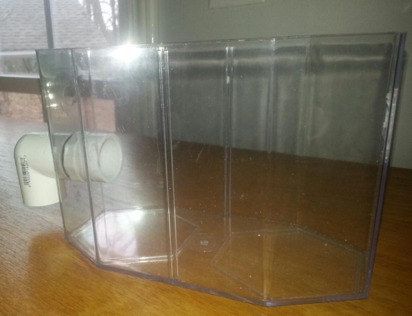 Figure 6: Representative fish tank. The fish tank contains a draining line that will connect with the horizontal draining lines in the system.
Discussion
The main purpose of this article is to demonstrate that the construction of a functional zebrafish facility is not complicated and can be built by novice fish researchers with minimal construction knowledge. Furthermore, this article shows that the materials for this functional zebrafish facility can be acquired readily and affordably from local pet supply stores or hardware stores. Once all the materials and tools have been acquired the construction of the system and the fish tanks takes about one working day. The 72 hr first run allows any failure in the system, such as leaks or low water pressure, to be determined. This first run also allows for contaminants within the system to be removed from circulation. For example, the PVC glue may contain hazardous organic material that will be removed during the first several hours of circulation. The system has a main draining valve that allows and facilitates the adjustment of volume and water replacement for maintenance. Additionally, the system has a pressure reliever line that also facilitates the adjustment of water pressure. This line is useful when only one or two compartments (shelves) will be used since it allows the regulation of water pressure.
The facility is modular in design allowing for the utilization of 1, 2 or 3 compartments (36 fish tanks of 1.8 L) to meet the capacity needs of individual researchers. The on-off valves placed in each compartment facilitate the isolation of the different parts of the system. This valve system is also useful to avoid potential infection dissemination, and to facilitate the cleaning of the system by compartments. In addition, every fish tank water supply has two valves, one at the 9 port irrigator and one at the flexible tubing at the entrance of the fish tank. This double valve system allows fine tuning of water pressure and also facilitate cleaning procedures or fish extraction or manipulation.
A proper documentation of ammonia, nitrite and nitrate is essential for the proper function of the facility. For this, the bioballs are important since they provide sufficient surface for nitrifying bacteria to growth. Once the fish colony is stable, the facility can be readily modified to use larger or smaller fish tanks. Also, the facility can be modified to breed zebrafish following the protocols available in the literature5. Furthermore, the facility can be modified to add other modules or racks to expand the capabilities of the system.
The flow of fresh water into the tank provides enough fresh oxygen so that there is no need to add an additional oxygenator. The air exchange that occurs in the water reservoir is a sufficient source of oxygen. If larger tanks are used then an additional oxygen source may be added. It should also be noted that without flow of fresh water into the tank the fish will suffocate, so it is vital that water flow be closely monitored to ensure nothing is blocking the water lines. It is essential that water temperature be maintained at 28.5 °C. A constant temperature may be achieved by maintaining the room temperature in which the system is housed at 28.5 °C. Alternatively, an aquarium heating source may be purchased in order to maintain a constant temperature. Maintaining water quality is essential to consistent experimental results. There are many sources available to help determine exact water quality parameters based on experimental conditions.
Fish tanks are cleaned every 7 - 10 days and subsequently sprayed with 70% alcohol before reuse. It is also suggested that the chrome rack be cleaned and dried at this point to prevent rust and build up. If signs of contamination are observed, individual tanks are disinfected with a 2% bleach solution8. General health is monitored with special attention to signs of infection (swelling, skin ulcers, exolpthalmia, color off, etc.), gas bubble disease (due to supersaturated gas concentrations, quick changes in water temperatures, problems in the plumbing system), gill hyperplasia (high levels of ammonia, copper, zinc or active chorine in the water), scoliosis (due to vitamin C deficiency) or egg associated inflammation and fibroplasias (due to female egg retention that pushes out the abdominal wall).
The construction of this facility is flexible and allows for a smaller or expanded system. By taking the basic construction ideas, this facility can be arranged to fit basic research needs of various sizes. Because construction may vary by institution, the most critical step in the protocol is the 72 hr first run, and the daily monitoring of ammonium, nitrate, and nitrite levels during the first week of construction. Excellent water quality will aid in maintaining the health of the fish. Many of the current protocols available for an affordable fish system require an open-air water-flow3. Having water protected from the open-air minimizes chance for water contamination and evaporation. Maintenance on a closed system is minimal when compared to the common open-air systems.
If problems arise in the construction of the facility (leaks, low water pressure, etc.) one can replace a cemented pipe by simply cutting away the area of concern in the facility and replacing the parts in the same step-wise manner as listed above. This system may be vulnerable to large water loss due to small leaks, which may become hazardous to the fish if left unnoticed. For a minimum investment a float shut-off device will detect when the water level has dropped below a safe threshold and shut the system down. This may be necessary if close monitoring of the system is not available. With the correct modifications, there are very few limitations this system faces besides lack of mobility. Once this system is constructed it is very difficult to move without cutting some parts and recementing them in the new location. This mobility limitation means that the system will ideally need to be maintained in one workspace. If mobility is desired there are small modifications that may be made to increase flexibility. Add a union at the beginning of each supply lateral, the pressure relief line, the pump discharge, and above the drain valve. The drain lines can be dry fitted instead of cemented in place. Adding a flexible coupling to the pump section will also aid in mobility. This is an additional
The simple construction and maintenance of this system means that current protocols found in the literature are available to small research institutions1,2,10-12. Maintenance is simple making this an ideal system for undergraduate student research. This system is excellent for independent research and teaching labs, also.
In conclusion, this type of facility is affordable, easy to build, and functional for in vivo experimentation. This facility is ideal for institutions with limited resources and limited animal husbandry space. Zebrafish research is an area that is used for multiple types of studies, including pharmacology, physiology, development, or even genetic studies. In fact, the large number of available mutant or transgenic zebrafish supports innovative lines of research in virtually all fields of biomedicine. In addition, this system can be used to enhance research opportunities and classroom experiences for science majors at small predominantly undergraduate institutions and inspire the next generation of biomedical scientists.
Disclosures
The authors declare no conflicts of interest for this paper.
Acknowledgments
The authors would like to thank the Office of Research of Presbyterian College School of Pharmacy for financial support of this project through the Small Pharmacy Awards for Research & Collaboration (SPARC) Award. The authors thank Mr. John Smink, Manager of the Aquatic Animal Research Laboratory, Clemson University, Clemson, SC for his technical assistance manuscript revision.
References
- Detrich H, Westerfield M, Zon L. The Zebrafish: Cellular and Developmental Biology, Part A. 3rd ed. New York, New York: Academic Press; 2010. [DOI] [PubMed] [Google Scholar]
- Grim JM, et al. Hemogen (hemgn), a transcription factor that regulates erythropoiesis and skeletogenesis in zebrafish. Strategic Conference of Zebrafish Investigators Poster Presentation; 2013; Asilimar, CA. 2013. [Google Scholar]
- Kim S, Carlson R, Zafreen L, Rajpurohit SK, Jagadeeswaran P. Modular, easy-to-assemble, low-cost facility. Zebrafish. 2009;6(3):269–274. doi: 10.1089/zeb.2009.0587. [DOI] [PMC free article] [PubMed] [Google Scholar]
- Linbo TL. Zebrafish (Danio rerio) husbandry and colony maintenance at the Northwest Fisheries Science Center. U.S. Dept. Commer., NOAA Tech. Memo. 2009;62 [Google Scholar]
- Avdesh A, et al. Regular care and maintenance of a zebrafish (Danio rerio) laboratory: an introduction. J Vis Exp. 2012;69:4196. doi: 10.3791/4196. [DOI] [PMC free article] [PubMed] [Google Scholar]
- McNabb A, Scott K, Ochsenstein E, Seufert K, Carl M. Don't be afraid to set up your fish facility. Zebrafish. 2012;9(3):120–125. doi: 10.1089/zeb.2012.0768. [DOI] [PubMed] [Google Scholar]
- Garcia RL, Sanders GE. Efficacy of cleaning and disinfection procedures in a zebrafish rerio) facility. J Am Assoc Lab Anim Sci. 2011;50(6):895–900. [PMC free article] [PubMed] [Google Scholar]
- Rivas-Boyero AA, et al. Pharmacological characterization of a nociceptin receptor from zebrafish (Danio rerio) J Mol Endocrinol. 2011;46(2):111–123. doi: 10.1530/JME-10-0130. [DOI] [PubMed] [Google Scholar]
- Sanchez-Simon FM, Zhang XX, Loh HH, Law PY, Rodriguez RE. Morphine regulates dopaminergic neuron differentiation via miR-133b. Mol Pharmacol. 2010;78(5):935–942. doi: 10.1124/mol.110.066837. [DOI] [PMC free article] [PubMed] [Google Scholar]
- Velasco EM, Law PY, Rodríguez RE. Mu opioid from the zebrafish exhibits functional characteristics as those of mammalian mu opioid receptor. Zebrafish. 2009;6(3):259–268. doi: 10.1089/zeb.2009.0594. [DOI] [PubMed] [Google Scholar]


