Abstract
Adsorption and assembly of colloidal particles at the surface of liquid droplets are at the base of particle-stabilized emulsions and templating. Here we report that electrohydrodynamic and electro-rheological effects in leaky-dielectric liquid drops can be used to structure and dynamically control colloidal particle assemblies at drop surfaces, including electric-field-assisted convective assembly of jammed colloidal ‘ribbons’, electro-rheological colloidal chains confined to a two-dimensional surface and spinning colloidal domains on that surface. In addition, we demonstrate the size control of ‘pupil’-like openings in colloidal shells. We anticipate that electric field manipulation of colloids in leaky dielectrics can lead to new routes of colloidosome assembly and design for ‘smart armoured’ droplets.
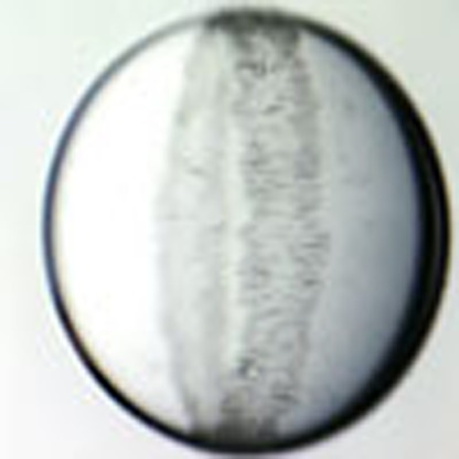 The self-assembly of colloidal structures at liquid interfaces finds immediate application in industry, such as food and drug encapsulations. Dommersnes et al. develop a technique to manipulate the distribution of colloidal particles adsorbed on drop surfaces under an applied electric field.
Colloidal particles can bind strongly to fluid interfaces and assemble into thin layers. Monodisperse colloidal beads can form two-dimensional (2D) ordered colloidal crystal monolayers1,2,3, and poly-disperse and anisotropic particles form amorphous shells4,5,6. This effect is currently much studied in relation to particle-stabilized ‘Pickering’ emulsions7,8,9 where particle coatings on droplets effectively prevent droplet coalescence and produce very stable surfactant-free emulsions. Emulsions are ideal templates for producing particles and capsules10. Solid colloidal capsules, colloidosomes, can be produced by fusing or linking colloidal particles at the surface of Pickering emulsions droplets11.
Particle-stabilized emulsions and their use as templates for making colloidal structures have a vast range of applications, notably in food processing12, biomedicine13,14 and petroleum industry15. It is increasingly realized that the colloidal-coated particles can have a role that goes beyond mere encapsulation: colloidal particle surface properties and volume can respond to temperature and solvent changes, colloidal particles can also be manipulated by external fields and act as catalyst to chemical reactions. This opens up for new possibilities for the use and control of emulsions and colloidal capsules: controlled release, with possible applications to drug delivery, has been achieved from pH-responsive colloidal capsules16, and pH-responsive particles have been shown to act as reversible on/off emulsifiers for Pickering emulsions17. Emulsions stabilized by paramagnetic colloidal beads have been shown to undergo controlled phase separation in response to magnetic fields18. Solid particles can also stabilize water–oil emulsions and simultaneously catalyse biomass refining reactions at the liquid interfaces19.
Droplet-based templating10 include, for example, production of colloidosome capsules11 or new porous structures20. Controlled production of anisotropic colloidosomes, either in shape or surface material composition, will likely have an important role in the development of colloidosome materials technology. Non-spherical droplets have been produced from double-emulsion templates or by ‘arrested’ droplet coalescence21,22, and Janus colloidal shells, composed of two different colloidal hemispheres, can be produced by targeted delivery of colloidal particles in a microfluidics setup23.
Although electric fields are commonly used for emulsion breaking, there appears to be few studies of Pickering droplets subjected to electric fields. It has been shown that particles adsorbed on droplets can be manipulated by AC electric fields by dielectrophoresis (DEP) effects24,25,26, and electric fields can also be used to remove particles from droplet surfaces due to droplet breakup and tip streaming27.
Here, we wish to bring to attention the possibilities offered by electric fields for assembly and manipulation of colloidal armour on liquid droplets. We demonstrate a new route of colloidal surface self-assembly in a simple setup including electrohydrodynamic (EHD) circulation flows in leaky-dielectric drops. Oil-in-oil emulsion droplets in electric fields have been extensively studied, and constitute a classic example of electric field-induced hydrodynamic flow, as described by the Taylor–Melcher leaky-dielectrics model28,29. Here, we show that colloidal particles are carried by EHD convective flow, concentrating the particles in a dense packed colloidal ribbon on the drop surface. This is reminiscent of the ‘coffee-ring’ effect, which is owing to colloidal particles carried by capillary convective flow in an evaporating droplet30. In addition, we show that colloidal ribbons, once assembled, can be dynamically modulated by tuning the electric field strength, provided the colloidal particles are polarizable and can form dipolar chain structures on the drop surface. To our knowledge, this is the first realization of a Winslow electro-rheological type system31,32 confined to a 2D surface.
Results
Colloidal clay ribbons
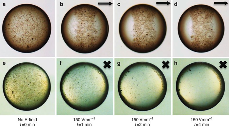
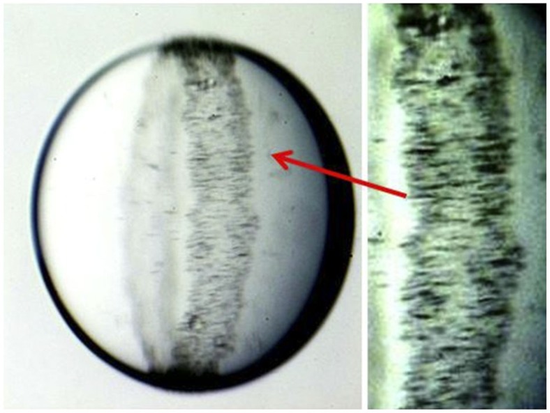
A millimeter-sized clay-silicone (1 wt% clay) drop is immersed in castor oil, see Fig. 1. The clay is dispersed throughout the drop. The top row of images is taken perpendicular to the applied electric field, whereas the bottom row is in the direction of the field (as seen through transparent electrodes). A DC electric field of strength 150 Vmm−1 is applied across the cell. Circulation flows can be seen inside the drop immediately after application of the electric field. A ribbon-shaped film builds up at the drop surface in less than a minute, and in about 4 min the drop becomes transparent in the direction of the field, indicating that clay particles have migrated to the surface ribbon. After the initial assembly dynamics, a steady state exists with a stable ribbon. The film is disordered, containing small aggregates of clay particles. The boundary of the ribbon is sharp, suggesting that the clay particles are closely packed or cohesive. Once adsorbed, the clay particles seem to be bound irreversibly to the interface: turning off the electric field only results in slow disruption of the ribbon, but the clay particles still remain on the surface of the drop. At slightly higher field strengths, the steady-state ribbon clearly contains dipolar electro-rheological chain structures, see Fig. 2.
Figure 1. Assembly of colloidal clay surface ribbon.
A silicone oil drop of radius 0.7 mm with Fh clay particles initially dispersed throughout the drop. The drop is immersed in castor oil. The arrows and crosses indicate the direction of the E-field. The four upper panels (a–d) are viewed perpendicular to the E-field direction, while the four lower panels (e–h) are viewed along the E-field direction. (a,e) Show the situation before the electric field is turned on, and (b–d) and (f–h) after a DC electric field is applied. Hydrodynamic circulation flows are observed in the drop, and in a few minutes clay particles are concentrated in a ribbon-shaped film on the drop surface.
Figure 2. Perspective view displaying the surface clay ribbon film on a drop.
Drop radius is 1 mm. 2D dipolar chain formation of clay particles can be seen in the ribbon. Electric field strength is 200 Vmm−1.
The formation of the ribbon must involve two processes: (1) transport of clay particles from the drop bulk to the drop interface and (2) assembly of the ribbon film on the drop interface. It is well documented that colloidal particles adhere strongly to oil–water interfaces. For example, clay particles are known to absorb strongly at oil/water interfaces and produce stable emulsions9. This is generally attributed to capillary binding: a particle at the interface is trapped in a capillary barrier with a substantial energy cost of moving to either side of the liquid interface7. The typical surface tension between water and many oils is  mNm−1, and the resulting binding energy of micron-sized particles at oil–water interfaces is very high compared with thermal energies,7 ΔE~103kBT. The surface tension between castor oil and silicone oil is33 γo–o≈4.5 mNm−1, an order of magnitude lower than oil–water tension, but the capillary binding energy is still likely to be very high compared with thermal energies, explaining the strong affinity of clay to the castor/silicone oil interface.
The width of the ribbon depends on the initial clay concentration in the drop: for an electric field of 200 Vmm−1 and clay concentration 1.5 wt% the ribbon almost covers the drop, while for 0.5 wt% the ribbon is narrow (see the Supporting Information). Assuming that the majority of clay particles have migrated into the ribbon, we may estimate the average thickness of the clay ribbon: The density ratio of clay and oil is ~1.5–2, and 1.5 wt% is equivalent to ~1% by volume of clay. In the case where the clay completely covers the drop surface, the thickness of the film is d=cr/3, where c is the initial volume percentage of clay inside the drop and r the drop radius. For a mm-sized drop with 1.5 wt%, this would give a shell thickness of d~3 μm, which is in the same size range as the fluorohectorite (Fh) clay particles used here, suggesting that the film is composed of just a few layers of clay particles.
The timescale for a clay particle of size b~μm to diffuse 1 mm in 100 cSt silicone oil is roughly t~103 days, and therefore hydrodynamic flow, sedimentation or electric forces are required to transport clay particles to the drop surface at the timescales reported above.
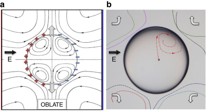
In an emulsion formed by two leaky-dielectric liquids, such as two oils, free charge accumulation can result in a Maxwell electric stress that sets up liquid circulation flows inside and outside the drops28,29. When the drop is less conducting than the surrounding liquid (such as silicone drop in castor oil), the circulation flow is directed towards the drop equator, as shown in Fig. 3a. We have observed the flow, both outside and inside the drop. Tracing paths were made by following one polyethylene (PE) particle inside and a few beads outside the drop, see Fig. 3b. If the drop is more conductive than the surrounding liquid, then the flow is reversed, and also significantly weaker. For a silicone drop in castor oil, the Taylor model28 predicts that the induced velocity at the surface is 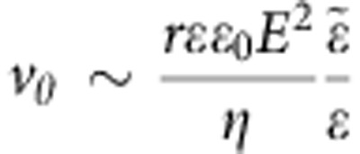 and directed to the drop equator (see Methods). The timescale to convect a particle towards the equator is
 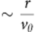 , which in a field of 150 Vmm−1 gives a timescale of t~7 s (see Methods). This shows that Taylor flow is sufficiently strong to induce the ribbon formation during the measured timescale. The process is likely slowed down by the presence of clay particles, as they modify both the electric field around the drop and the EHD flow. The increased conductivity of the drop owing the clay film will reduce the free charge buildup and therefore also reduce the induced hydrodynamic flow.
Figure 3. Hydrodynamic streamlines in Taylors electrohydrodynamic drop model.
The model is valid for a silicone drop in castor oil (a). Adopted from ref. 28. This flow, both outside and inside the drop, is observed experimentally (b). Tracing paths are made by following PE beads outside and one particle inside a drop of radius of about 1 mm. Arrows indicate the direction of the flow. The E-field direction is horizontal in the plane of the panels, as indicated by the arrow. For the side view of the internal particle trace (in the direction of the electric field), see Supplementary Fig. S1.
It has previously been observed that large colloidal particles adsorbed at droplet interfaces can migrate to the ‘equator’ or the ‘poles’ of the droplet when subject to an AC field24,26 owing to DEP of particles on the droplet surface: polarizable colloidal particles are subject to forces in non-uniform fields at the droplet surface, the force being proportional to the gradient of the square of the field strength. This effect should also contribute in our case, as clay is polarizable, and should therefore be attracted towards stronger electric fields at the droplet equator. We have previously shown that suspended clay particles are significantly more conductive than oil34, and therefore can be considered as conductors when subject to a DC field. The force on a spherical particle of radius b in an inhomogeneous DC electric field is  , where εε0 is the dielectric constant of the fluid medium, σp and σm are the conductivities of the colloidal particle and the fluid medium, respectively35. This expression for FDEP is valid provided that the size of the polarized particle is small compared with the length scale of the non-uniformity of the electric field. This is justified in the present case because the inhomogeneity of the electric field is given by the drop size, which is of the order of 1 mm, and the size of the clay colloidal particle is in the range of 1–10 μm. As in the present case σp>>σm and
 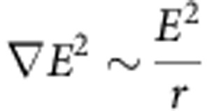 , then
  . Balancing the hydrodynamic drag ~ηb and the dielectrophoretic force thus gives a dielectrophoretic velocity of the order
 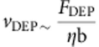 . The ratio of the EHD and dielectrophoretic velocities is
  , meaning that dielectrophoretic effects are not significant here. This we have verified experimentally by using non-polarizable particles, for which we observed ribbon formation on similar timescales as for clay, see Supplementary Fig. S1.
The Maxwell–Wagner charge relaxation time for the silicone in castor oil system is τMW≈1 s. Taylor EHD flow will therefore be suppressed at AC frequencies much larger than 1 Hz (ref. 29). This is consistent with our observation that for clay–oil drops in AC fields, we only obtain ribbon formation at very low frequencies (0.1 Hz), and the ring gradually becomes wider as the frequency is increased.
Although EHD flow accounts for the stability of the ribbon once formed, it does not directly explain the migration of clay to the interface. It is not evident that the flow can direct particles from the bulk to the surface, as the flow component normal to the surface vanishes. Thus, particles carried by Taylor–Melcher circulation streamlines will approach the drop surface, but they eventually turn before adsorbing. In (refs 23, 36) it was observed that efficient colloidal assembly on droplets by hydrodynamic flow requires finite Reynolds number flow, that is, inertial effects. As clay forms dipolar chains on the drop surface, see Fig. 2, there must be significant electric field-induced short-range dipole interactions between the particles, suggesting that clay near the drop surface could simply be attracted to the clay that is already trapped. Another contributing mechanism could be charge uptake on clay particles, which could drive them in the electric field to directly hit the surface and adsorb. For drops only subjected to high-frequency AC field, we do not observe migration of clay particles towards the drop surface, the particles rather appear to form chains inside the drop. In this case, the dipole interactions alone are not sufficient to direct clay to the surface, suggesting that DC-induced EHD convection and clay particle dipole interactions work together to enhance the rate of clay adsorption to the drop interface.
The clay film can be considered as a 2D electro-rheological fluid with dipolar chain formation, see Fig. 2. The tangential component of electric surface field in particle-free oil drops is  . The conductivity of castor oil is much higher than silicone oil, hence the field at the equator (
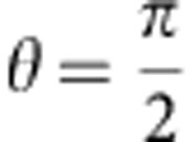 ) is
) is 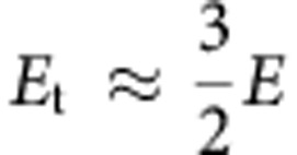 . In 3D bulk suspension, we have previously observed clay chain formation above E~350 Vmm−1 (refs 32,34); if we assume similar dynamics in 2D, one expect to see chain formation at droplet surface for applied field of roughly E~230 Vmm−1, in fair agreement with the observations.
At field strengths below 250 Vmm−1, we observe axisymmetric clay ribbon formation, either thin or thick ribbons, depending on the initial clay concentration. However, at increased field strengths the drop response depends on clay concentration.
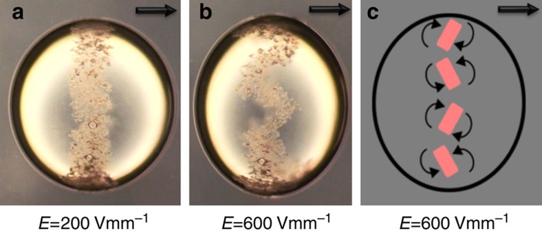
At lower clay concentration (0.5 wt%), increasing the field strength induces an instability of the ribbon, it breaks up into several counter-rotating colloidal assemblies (shown in Fig. 4 and Supplementary Movie 1). Particles that are less conducting than their surrounding liquid can spin in DC electric fields, known as Quincke rotation37. In the present case, clay is more conducting than the surrounding liquid, and we therefore exclude Quincke rotation as the mechanism here. However, our observations are in line with previous work showing that conducting particles in bulk can assemble and form counter-rotating vortices38.
Figure 4. Breakup of clay ribbon into rotating domains.
Clay concentration is 0.5 wt%. The ribbon is stable at field strength of 200 Vmm−1 (a). At 600 Vmm−1 (b), the ribbon breaks up into several domains with continuous rotation (vortices) as illustrated in the cartoon (c). The drop remains oblate even at high fields, similar to a pure silicone drop in castor oil that experience EHD flow deformation (see also Supplementary Movie 1). The drop radius is about 1 mm. The E-field direction is horizontal in the plane of the panels, as indicated by the arrows.
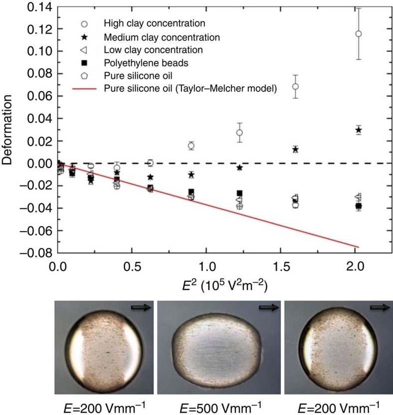
At higher clay concentrations, the ribbon width increases when the electric field is increased, as shown in Fig. 5. This is opposite to what can be expected within the Taylor–Melcher model for a particle-free pure oil drop where the EHD flow increases with field strength, which should result in increased compression of the ring and not stretching. We have previously observed that Fh chain formation in silicone oil gives non-ohmic response and strongly enhanced conductivity34, and in the present case, this should diminish the charge buildup on the drop, and thereby suppress the EHD flow. A similar effect is seen in the drop deformation: At high fields and high clay concentrations, the drop deformation can change from oblate to prolate as shown in Fig. 5, indicating that the EHD Taylor flow is suppressed or reversed28.
Figure 5. Drop deformation as a function of the square of the electric field strength.
Pure silicone drops are oblate (drop deformation D<0) and the measurements for weak deformations (−0.04<D<0) quite accurately follow the prediction of Taylor–Melcher perturbation theory. Drops with low clay concentration almost follow the same curve as drops without clay. However, with higher clay concentrations the behaviour is qualitatively different: at low field strengths the drop is oblate, but as the field strength increases the drop deformation reverses from oblate to prolate (D>0). This behaviour coincides with the nonlinear electric response of clay particles, at high field strengths clay form increasingly longer conductive dipolar chains that effectively can short-circuit the silicone drop. The three images at the bottom show how a drop with clay concentration in the medium to high regime (that is, 1–1.5 wt%) deforms reversibly as the electric field strength is increased and decreased. The drop radius is about 1 mm. The E-field direction is horizontal in the plane of the panels, as indicated by the arrows.
Clay pupil
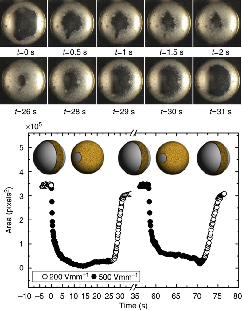
The above observations suggest that such colloidal films can be actively controlled by electric fields. As a simple illustration of this, we have performed experiments in which we switch between two different field strengths, one that induces a narrow ribbon formation, and a higher field that actively stretches the ribbon and covers the drop, see Fig. 6. Seen through the electrodes, this has the appearance of an expanding and contracting ‘pupil’. The fact that the film rapidly covers the surface at higher field strength cannot be attributed to clay wetting dynamics at the interface (Marangoni), as turning the field off does not lead to rapid coating. There must therefore be an electrically induced force that actively stretches the film armour. The clay itself will modify the electric field, as clay is more conductive than both oils. Thus, there will be free charge accumulation at the edge of the ribbon, and the electric field acting on these charges could induce electro-stretching of the film. A drop fully covered with dense colloidal armour of conducting colloidal particles can be considered as a Faraday cage screening the internal electric field23, and hence removing the necessary conditions for Taylor–Melcher flow.
Figure 6. Actively contracting and expanding pupil armour.
This is shown in the series of ten images on the top. The drop is viewed along the E-field direction, as indicated by the crosses. At 200 Vmm−1, the drop (of a radius about 1 mm) is partially covered by a clay ribbon, and at 500 Vmm−1 the drop is nearly fully covered. The timescale of switching is seconds (see also Supplementary Movie 3). This is a reversible process as displayed in the bottom panel, where we plot the area of the pupil opening versus time (following changes of the electric field strength). The cartoons in the inset display a perspective view of the process.
A complete understanding should take into account the electrohydrodynamic response of the combined colloidal clay–oil systems, including the non-ohmic conductivity of the clay film. For example, for pure particle-free drops the type of axisymmetric deformation is not field dependent, and is either always prolate or oblate depending on the relative dielectric constant and conductivity of the two liquids29. A pure silicone oil drop in castor oil is oblate; however, with clay particles present, we observe that the drops can switch to prolate deformation as the field strength is increased, as illustrated in Fig. 5. This is consistent with the clay film having a non-ohmic response. In pure drops, it is the Maxwell–Wagner times that decide whether a drop is oblate or prolate, whereas with clay the charge accumulation is dependent on field strength, making it possible to switch from oblate to prolate as the conductivity increases.
For higher clay concentrations (above about 2 wt%), the drop surface seems to be covered by a clay armour, and asymmetric drop stretching occurs. We observe breakup at field strength of 400 Vmm−1 and above, in contrast to pure silicone oil drops that are only weakly deformed at such field strengths.
To investigate the robustness of the clay pupil effect, we performed equivalent experiments on several different types of clay (Supplementary Table S1). It was found that four clay samples exhibited the pupil effect. The presence of pupil effect correlates with high clay conductivity, supporting the hypothesis that the pupil closing is related to conductive dipolar clay chains short-circuiting the drop.
Insulating colloidal beads
Clay particles are more conductive than silicone oil. We therefore also investigated electrically insulating beads, with dielectric constant similar to that of silicone oil, and thus practically unpolarizable in the present experiments (for example, polystyrene or PE). Therefore, there should be no noticeable dipole interactions between the insulating beads in our case, and also the conductivity of the drop should not be enhanced. Nevertheless, we observe insulating colloidal ribbon formation, on a similar timescale as for clay particles (Supplementary Fig. S2). However, in most of the experiments with insulating beads, many beads continue to move around inside the drop, and only after applying the DC field for significantly longer times all the beads will go to the surface. This supports the idea that electric forces or sedimentation aid the clay particle to absorb on the drop interface, as discussed above. As for the clay particles, at higher fields we observe breakup of the colloidal ribbon into several small rotating domains (Supplementary Fig. S3 and Supplementary Movie 2), similar to the dynamics observed in clay ribbons at lower concentration, see Fig. 4. Both for the polystyrene and PE beads, we observe that the domain rotation frequency at 300 Vmm−1 is of order of magnitude 0.1 Hz and increases with electric field with a rate of ~4 × 10⁻⁴ mmV−1s−1 (within the range of 275–375 Vmm−1). In the range 200–270 Vmm−1 there is ribbon deformation and the domains are not clearly defined. At even lower fields, that is, below 200 Vmm−1, the ribbon is static. The rotation frequency does not appear to follow the E2 behaviour of the Taylor–Melcher model, suggesting that this may be a different kind of flow instability. With insulating particles, we always observe oblate drop deformation, suggesting that it is the conductive properties of clay that induces prolate deformations.
We have also performed additional experiments with 20 × smaller polystyrene beads and we observed that the time it takes for beads to adsorb onto the drop surface is noticeably longer than for larger beads. We attribute this to the role of sedimentation in aiding the Taylor–Melchor flow in the process of bringing particles onto drop surfaces.
Conducting colloidal beads
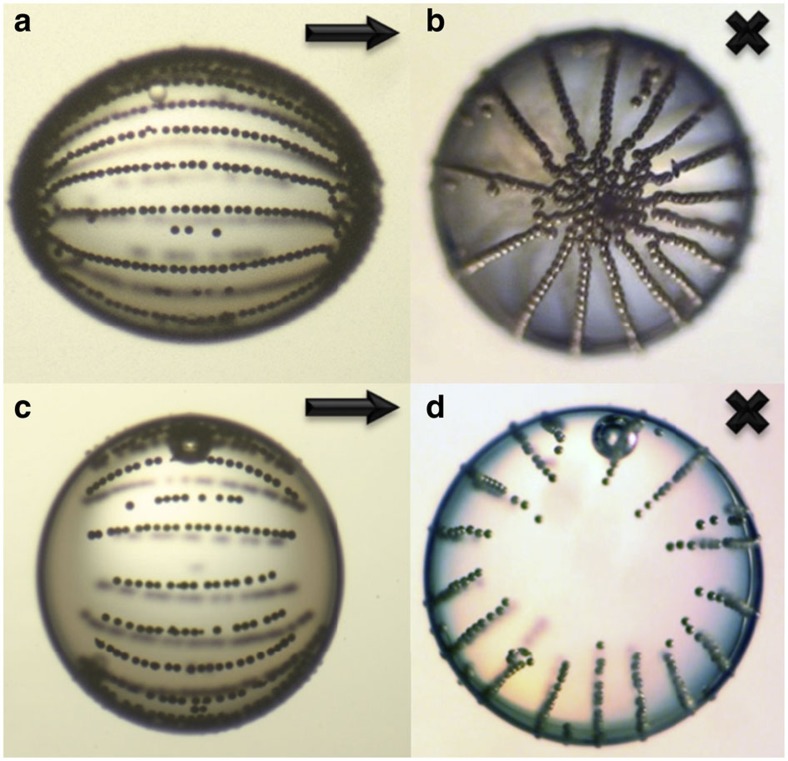
To emulate the conductive properties of clay on drop surfaces, we also performed experiments with conductive silver-coated beads inside silicone drops immersed in castor oil. The beads are rapidly transported to the drop surface where they form chains; see Fig. 7, similar to the clay particle case shown in Supplementary Fig. S4. We also observe a very similar transition from oblate to prolate deformation. With sufficient number of beads to form long chains spanning the drop, the drop takes a prolate deformation, see Fig. 7a. This indicates that the increased conductivity suppress Taylor–Melcher flow associated with oblate deformation. With fewer beads, the drop is oblate, see Fig. 7b.
Figure 7. Drop behind bars.
(a,b) Conducting beads on the surface of a silicone drop with a radius of about 1 mm embedded in castor oil: the beads attract and form chains, resulting in a colloidal bar armour. The drop now has a prolate shape, owing to the increase in electric conductive from the chains, which short-circuit the drop and supress the free surface charges inducing the Taylor–Melcher EHD flow. (c,d) At lower bead concentration, the chains do not span the entire drop, and the drop is oblate, indicating presence of Taylor–Melcher EHD flow. The arrows and crosses indicate the direction of the E-field.
We have also investigated the role of the sedimentation in the process of bringing colloidal particles to the drop surface by conducting experiments with heavy silver-coated glass particles and we see that the sedimentation is significantly faster than that of lighter polymer beads investigated above. It can be seen that even in the case that almost all conductive particles sediment to the bottom of the drop, they self-organize themselves into chain structures spanning the entire drop surface, as shown in Supplementary Movie 4.
Discussion
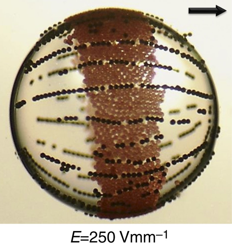
We have shown that electric fields can induce structural assembly of colloidal armour on oil drops, including ‘equatorial’ ribbons and ‘longitudinal’ dipolar chains. Electrohydrodynamic circulation flows inside the drop and dipole interaction between particles can account for the observations. The armour width can be actively controlled by the strength of the electric field and we have shown that this effect is intimately linked to the magnitude of polarizability contrast between particles and the drop oil and colloidal particle conductivity (Supplementary Table S1). Thus in the present experiments, the ‘pupil effect’ can only be observed with the clay particles, as our insulating beads only form equatorial ribbons, and metallic-coated particles only form chain-like structures. This is illustrated in Fig. 8, where we observe a drop covered simultaneously with insulating beads and metallic-coated glass beads. It would be interesting to extend this study to mixtures of different particles, which could lead to more advanced electrically controlled self-assembled surface structures. Solidification of these structures can be induced by UV light or heating to produce anisotropic functional colloidosomes11. The method we have demonstrated here is easily transportable to microfluidic devices that include use of electric fields39. Soft matter is characterized by being easily deformable by external fields or forces. The observed electro-stretching of the clay armour on drops is an example of 2D soft matter. To our knowledge, this is the first realization of a Winslow electro-rheological type system31,32 confined to a 2D surface. In 3D space, it is well established that electro-rheological chains often attract and form large bundles40. In our case, we did not observe bundling on drop surfaces, rather the chains repel each other, and are regularly spaced in a stable configuration.
Figure 8. Silicone oil drop covered simultaneously with PE beads and metallic-coated glass beads.
The applied electric field strength is 250 Vmm−1. The E-field direction is horizontal in the plane of the panels, as indicated by the arrow. The PE beads only form equatorial ribbons, and the metallic-coated particles only form chain-like structures. The dynamic ‘pupil effect’ observed for clay particles (see Fig. 6) cannot be realized for any of these cases in the present experiments. The drop radius is about 1 mm.
It should be possible to design other ‘soft capsules’ that respond to external fields. We believe that the results presented here can lead to new methods for assembly of colloidal particles on drops leading to advanced emulsion and template-based design. It is possible to mass produce various colloidal shells (ribbons, pupils, and so on) and this is shown in Supplementary Fig. S5, where ribbons of Fh clay particles are viewed at an angle ~60° with respect to the direction of electric field (a); whereas the opening and closing of pupils for multiple droplets are shown in (b) and (c), respectively. At very high droplet numbers, the mass production is hampered by droplet coalescence.
Methods
Sample cell
The experiments are performed in a square glass cuvette (10 × 10 × 30 mm3), in which two sides are made of transparent ITO (indium tin oxide) electrodes, allowing observation of drops both parallel and perpendicular to the applied electric field. In all images, the direction of gravity is downward.
Oils
The cell is filled with castor oil (Sigma-Aldrich 83912, specific density of 0.961 gcm−3 at 25 °C, electric conductivity 45 pSm−1, relative permittivity 4.7 and viscosity 1000 cSt). Silicone drops (Down Corning 200/100 cSt, Prod 630074A, specific density of 0.97 gcm−3, electric conductivity ~3–5 pSm−1, relative permittivity 2.1) containing colloidal particles are put into the castor oil using a pipette.
Clay minerals
Fh (fluorohectorite with different exchangeable cations, that is, Na, Li, Fe and Cu in the present case) and Laponite are synthetic 2:1 clay minerals. The Fh clay minerals used here comes from the same batch of materials as reported and characterized by Hansen et al.41 and references therein. Na-MMT (sodium-montmorillonite) and Vermiculite are commercially available natural 2:1 clay minerals. Kaolinite and Halloysite are commercially available natural 1:1 clay minerals. Quick clay is a mixture of geologically available natural clays.
Other colloidal particles
Silicone drops with colloidal beads are also studied: Fluorescent PE beads (UVPMS- BY2 45–53 μm) and conductive silver-coated glass beads (SLGMS- AG 45–53 μm) were purchased from Cospheric LLC; polystyrene beads (Dynoseeds CS40 and CS2) of diameter 40 and 2 μm were purchased from Microbeads.
Preparation of colloidal dispersions
Silicone oil and clay powders are measured by weight and stirred together followed by ultrasonic bath to avoid aggregation of clay particles.
Timescale for colloidal ribbon formation
The characteristic timescale for the EHD surface convection of particls can be estimated from the Taylor–Melcher model: the surrounding liquid (castor oil) has electric conductivity σ, dielectric constant ε and viscosity, and for the drop (silicone oil) the corresponding values are  ,
,  and
and  . The flow velocity is conveniently expressed in terms of the ratios28:
 |
In this notation, the EHD flow velocity at the drop boundary is28:
 |
where r is the drop radius, θ the polar angle and E the electric field strength. Neglecting any drag on the particle, that is, assuming it follows the flow, the time required to convect a surface-adsorbed particle to the ring is  . For castor oil and silicone oil, the timescale is:
For example, for a field strength of E=100 Vmm−1, the corresponding timescale is t~17s, which compares well with the experiments on PE particles, whereas in a field E=200 Vmm−1, the timescale is t~4s (see also Supplementary Fig. S6 and Supplementary Fig. S7). These values are approximate and valid in the dilute limit. For higher colloidal concentration and as the ribbon becomes wider (see Supplementary Fig. S8), the EHD flow is reduced.
AC electric fields
According to the Taylor model, EHD flow in a drop is generated by surface eletrostatic stress due to buildup of free charges at the drop surface. If the AC field has a period much shorter than the Maxwell–Wagner relaxation time, there will essentially be no buildup of free charges. The Maxwell–Wagner charge relaxation time of a drop (sphere) is  , where
  and σ are the dielectric constant and electric conductivity of the surrounding liquid (castor oil) and
  and
and  that of the drop, taking the known values for castor and silicone oil gives
  s. The presence of particles will of course modify the effective conductivity and dielectric constant, but roughly the EHD flow should be absent for AC frequencies much larger than 1 Hz, and for frequencies much lower than 1 Hz one expects EHD flow with the same direction as in a DC field (the EHD is independent of the direction of the electric field), but oscillating between zero flow and a maximum flow rate at the peak of the AC field. In Supplementary Fig. S9, we show experiments of the same drop, first in 50 Hz, 1 Hz, then 0.1 Hz and field amplitude of 100 Vmm−1. Ring formation is only seen in the 0.1 Hz, supporting the hypothesis that ring formation is driven by EHD flow.
Author contributions
P.D., Z.R. and J.O.F designed all experiments. Z.R., K.H., R.C., K.K. and A.M. performed the experiments. All authors contributed to the data analysis as well as to the presentation of the results. P.D. wrote the initial manuscript and Z.R., A.M., R.C. and J.O.F. all contributed to, and took part in writing and discussions towards, the finalization of the manuscript.
Additional information
How to cite this article: Dommersnes, P. et al. Active structuring of colloidal armour on liquid drops. Nat. Commun. 4:2066 doi: 10.1038/ncomms3066 (2013).
Supplementary Material
Supplementary Figures S1-S9 and Supplementary Table S1
At 0.5 wt.% the ribbon is unstable at high field strength. At 600 Vmm-1 the ribbon breaks up into several domains with continuous rotation (vortices). The drop remains oblate even at high fields, similarly to a pure silicone drop in castor oil which experience EHD flow deformation. The drop radius is about 1 mm and the E-field direction is horizontal. Real time movie.
Actively contracting and expanding 'pupil' armour: At 200 Vmm-1 the drop is partially covered by a clay ribbon; at 500 Vmm-1 the drop is almost fully covered. The process is reversible. The timescale of switching is seconds. The drop of radius about 1 mm is viewed along the E-field direction. Real time movie.
Development of rotating domain structures after the electric field was suddenly increased from 0 to 375 Vmm-1 at time t=0. The colloidal beads have been previously brought to the drop surface. The drop of radius about 1 mm is viewed perpendicular to the E-field direction. Real time movie.
Silver coated glass particles sediment significantly faster than lighter polymer beads. The electric field of 200 Vmm-1 is applied and it can be seen that even in the case that almost all particles sediment to the bottom of the drop, they selforganize themselves into chain structures spanning entire drop surface. The drop of radius about 1 mm is viewed perpendicular to the E-field direction. Real time movie.
Acknowledgments
P.D. and J.O.F. thank R. Pynn and D. Bonn for fruitful and helpful discussions, and we thank K.J. Maloy for use of laboratory facilities for the experiments shown in Fig. 6. The work at the Norwegian University of Technology and University of Oslo was supported by the Research Council of Norway through the FRINAT Program.
References
- Pieranski P. Two-dimensional Interfacial colloidal crystals. Phys. Rev. Lett. 45, 569–572 (1980). [Google Scholar]
- Nikolaides M. G. et al. Electric-field-induced capillary attraction between like-charged particles at liquid interfaces. Nature 420, 299–301 (2002). [DOI] [PubMed] [Google Scholar]
- Leunissen M. E. van Blaaderen A. Hollingsworth A. D. Sullivan M. T. & Chaikin P. M. Electrostatics at the oil–water interface, stability, and order in emulsions and colloids. Proc. Natl Acad. Sci. USA 104, 2585–2590 (2007). [DOI] [PMC free article] [PubMed] [Google Scholar]
- Yan N. X. & Masliyah J. H. Adsorption and desorption of clay particles at the oil-water interface. J. Colloid Interface Sci. 168, 386–392 (1994). [Google Scholar]
- Yue N. Xue M. & Qiu S. Fabrication of hollow zeolite spheres using oil/water emulsions as templates. Inorg. Chem. Comm. 14, 1233–1236 (2011). [Google Scholar]
- Tan S. -Y. Tabor R. F. Ong L. Stevens G. W. & Dagastine R. R. Nano-mechanical properties of clay-armoured emulsion droplets. Soft Matter. 8, 3112–3121 (2012). [Google Scholar]
- Aveyard R. Binks B. P. & Clint J. H. Emulsions stabilised solely by colloidal particles. Adv. Coll. Int. Sci. 100, 503–546 (2003). [Google Scholar]
- Pickering S. U. Emulsions. J. Chem. Soc. Trans. 91, 2001–2021 (1907). [Google Scholar]
- Ashby N. P. & Binks B. P. Pickering emulsions stabilised by Laponite clay particles. Phys. Chem. Chem. Phys. 2, 5640–5646 (2000). [Google Scholar]
- Shah R. K. et al. Designer emulsions using microfluidics. Mater. Today 11, 18–27 (2008). [Google Scholar]
- Dinsmore A. D. et al. Colloidosomes: selectively permeable capsules composed of colloidal particles. Science 298, 1006–1009 (2002). [DOI] [PubMed] [Google Scholar]
- Dickinson E. Food emulsions and foams: stabilization by particles. Curr. Opin. Colloid In. Sci. 15, 40–49 (2010). [Google Scholar]
- Shilpi S. Jain A. Gupta Y. & Jain S. K. Colloidosomes: an emerging vesicular system in drug delivery. Crit. Rev. Ther. Drug Carrier Syst. 24, 361–391 (2007). [DOI] [PubMed] [Google Scholar]
- Frelichowska J. et al. Pickering w/o emulsions: drug release and topical delivery. Int. J. Pharm. 371, 56–63 (2009). [DOI] [PubMed] [Google Scholar]
- Langevin D. Poteau S. Henaut I. & Argillier J. F. Crude oil emulsion properties and their application to heavy oil transportation. Oil Gas Sci. Tech.—Rev. IFP 59, 511–521 (2004). [Google Scholar]
- Cayre O. J. et al. pH-responsive colloidosomes and their use for controlling release. Soft Matter. 8, 4717–4724 (2012). [Google Scholar]
- Li J. & Stoever H. D. H. Doubly pH-responsive pickering emulsion. Langmuir. 24, 13237–13240 (2008). [DOI] [PubMed] [Google Scholar]
- Melle S. Lask M. & Fuller G. G. Pickering emulsions with controllable stability. Langmuir. 21, 2158–2162 (2005). [DOI] [PubMed] [Google Scholar]
- Crossley S. Faria J. Shen M. & Resasco D. E. Solid nanoparticles that catalyze biofuel upgrade reactions at the water/oil interface. Science 327, 68–72 (2010). [DOI] [PubMed] [Google Scholar]
- Ikem V. O. Menner A. Horozov T. S. & Bismarck A. Highly permeable macroporous polymers synthesized from pickering medium and high internal phase emulsion templates. Adv. Mater. 22, 3588–3592 (2010). [DOI] [PubMed] [Google Scholar]
- Lee D. & Weitz D. A. Nonspherical colloidosomes with multiple compartments from double emulsions. Small 5, 1932–1935 (2009). [DOI] [PubMed] [Google Scholar]
- Shum H. C. et al. Droplet microfluidics for fabrication of non-spherical particles. Macromol. Rapid Commun. 31, 108–118 (2010). [DOI] [PubMed] [Google Scholar]
- Subramaniam A. B. Abkarian M. & Stone H. A. Controlled assembly of jammed colloidal shells on fluid droplets. Nat. Mater. 4, 553–556 (2005). [DOI] [PubMed] [Google Scholar]
- Nudurupati S. Janjua M. Aubry N. & Singh P. Concentrating particles on drop surfaces using external electric fields. Electrophoresis 29, 1164–1172 (2008). [DOI] [PubMed] [Google Scholar]
- Hwang K. Singh P. & Aubry N. Destabilization of Pickering emulsions using external electric fields. Electrophoresis 31, 850–859 (2010). [DOI] [PubMed] [Google Scholar]
- Nudurupati S. Janjua M. Singh P. & Aubry N. Effect of parameters on redistribution and removal of particles from drop surfaces. Soft Matter 6, 1157–1169 (2010). [Google Scholar]
- Nudurupati S. Janjua M. Singh P. & Aubry N. Electrohydrodynamic removal of particles from drop surfaces. Phys. Rev. E 80, 010402 (R) (2009). [DOI] [PubMed] [Google Scholar]
- Taylor G. I. Studies in electrohydrodynamics. I. The circulation produced in a drop by electrical field. Proc. R. Soc. Lond. A 291, 159–166 (1966). [Google Scholar]
- Saville D. A. Electrohydrodynamics: the Taylor-Melcher leaky dielectric model. Annu. Rev. Fluid. Mech. 29, 27–64 (1997). [Google Scholar]
- Deegan R. D. et al. Capillary flow as the cause of ring stains from dried liquid drops. Nature 389, 827–829 (1997). [Google Scholar]
- Winslow W. M. Induced fibration of suspensions. J. Appl. Phys. 20, 1137–1140 (1949). [Google Scholar]
- Fossum J. O. et al. Intercalation-enhanced electric polarization and chain formation of nano-layered particles. Europhys. Lett. 74, 438–444 (2006). [Google Scholar]
- Salipante P. F. & Vlahovska P. M. Electrohydrodynamics of drops in strong uniform dc electric fields. Phys. Fluids 22, 112110 (2010). [Google Scholar]
- Rozynek Z. et al. Electric field induced structuring in clay–oil suspensions: new insights from WAXS, SEM, leak current, dielectric permittivity, and rheometry. J. Phys. Condens. Matter 22, 324104 (2010). [DOI] [PubMed] [Google Scholar]
- Jones T. B. Electromechanics of Particles Cambridge University Press (1995). [Google Scholar]
- Subramaniam A. B. Wan J. Gopinath A. & Stone H. A. Semi-permeable vesicles composed of natural clay. Soft Matter 7, 2600–2612 (2011). [Google Scholar]
- Quincke G. Ueber Rotationen im constanten electrischen Felde. Ann. Phys. Chem. 59, 417–486 (1896). [Google Scholar]
- Sapozhnikov M. V. Tolmachev Y. V. Aranson I. S. & Kwok W. K. Dynamic self-assembly and patterns in electrostatically driven granular media. Phys. Rev. Lett. 90, 114301 (2003). [DOI] [PubMed] [Google Scholar]
- Link D. R. et al. Electric control of droplets in microfluidic devices. Angewandte Chemie International Edition 45, 2556–2560 (2006). [DOI] [PubMed] [Google Scholar]
- Halsey T. C. Electrorheological fluids. Science 258, 721–834 (1992). [DOI] [PubMed] [Google Scholar]
- Hansen E. L. et al. Swelling transition of a clay induced by heating. Sci. Rep. 2, 618 (2012). [DOI] [PMC free article] [PubMed] [Google Scholar]
Associated Data
This section collects any data citations, data availability statements, or supplementary materials included in this article.
Supplementary Materials
Supplementary Figures S1-S9 and Supplementary Table S1
At 0.5 wt.% the ribbon is unstable at high field strength. At 600 Vmm-1 the ribbon breaks up into several domains with continuous rotation (vortices). The drop remains oblate even at high fields, similarly to a pure silicone drop in castor oil which experience EHD flow deformation. The drop radius is about 1 mm and the E-field direction is horizontal. Real time movie.
Actively contracting and expanding 'pupil' armour: At 200 Vmm-1 the drop is partially covered by a clay ribbon; at 500 Vmm-1 the drop is almost fully covered. The process is reversible. The timescale of switching is seconds. The drop of radius about 1 mm is viewed along the E-field direction. Real time movie.
Development of rotating domain structures after the electric field was suddenly increased from 0 to 375 Vmm-1 at time t=0. The colloidal beads have been previously brought to the drop surface. The drop of radius about 1 mm is viewed perpendicular to the E-field direction. Real time movie.
Silver coated glass particles sediment significantly faster than lighter polymer beads. The electric field of 200 Vmm-1 is applied and it can be seen that even in the case that almost all particles sediment to the bottom of the drop, they selforganize themselves into chain structures spanning entire drop surface. The drop of radius about 1 mm is viewed perpendicular to the E-field direction. Real time movie.


