Abstract
We have designed an intraocular telescope for the posterior chamber of the human eye of patients with age related macular degeneration. The basic design is composed of two decentered high optical power lenses ( + 66D and −66D) inducing a 3° prismatic effect to project a magnified central field of view into a healthier location off the central fovea. Aspheric surfaces were used to ensure a compromise between good optical quality and high tolerance to the final axial position of both lenses after surgery. With this particular design, the telescope affords an extended range of depth of focus, high tolerance to different axial lengths of the eye and robustness against typical values of astigmatism and higher order aberrations. The final design has been manufactured in a foldable material and is compact enough to facilitate surgical implantation. This telescope is a simple but promising intraocular visual aid for AMD patients.
OCIS codes: (330.7328) Visual optics, ophthalmic appliances; (330.4460) Ophthalmic optics and devices
1. Introduction
Patients with Age-related Macular Degeneration (AMD) can benefit from improved vision if a magnified image is projected on the retina to increase resolution. A number of telescopes have been developed to generate these augmented images. Typically, devices employ a Galilean telescope, consisting of two lenses: a positive (objective) lens and a negative (ocular) lens positioned at the corresponding focal distance. There have been several approaches that incorporate such systems into the optics of the eye. The simplest method is to use a regular spectacle lens to mount the telescopes. The telescope might be located on the central field of the spectacle lens (for reading tasks), but more commonly in the upper field as a bioptic approach for distance tasks, and they can be used binocularly or monocularly (binocular multiplexing) [1]. There are intrinsic limitations to this approach, from cosmetic [2] to more fundamental issues, in particular, these devices have a restricted field of view [3,4] that necessitates the continuous scanning of objects using movements of the head. Alternatives to spectacle mounted telescopes, include the combination of a high positive power spectacle lens with a high negative power contact lens [5] or an intraocular lens [6] (after removal of the crystalline lens optics in cataract surgery) to form a magnified images on the retina. Although both alternatives have better acceptance based on cosmetics, the field of view is still as limited as that spectacle mounted telescopes.
To increase the field of view and reduce the dependence on head movements, fully intraocular telescopes have been proposed. They are formed by two intraocular lenses (with positive and negative dioptric power) implanted into the eye after cataract surgery [7–11], or using a single lens that contains two mirrors forming a Cassegrain telescope [12]. At least three of these devices are in clinical use today. The Implantable Miniaturized Telescope (IMT; VisionCare Ophthalmic Technologies, Saratoga, CA) [7,8,13] consist of two lenses embedded in a cylinder glass tube with two optical windows that creates an air space around the lenses to achieve magnification between 2.2X and 3X depending on the viewing distance. The tube is 4 mm length and is implanted in the capsular bag using the iris to support and center the optical system. There are some concerns about the size and the surgical procedure to implant the device (it requires a 10 to 11 mm limbal incision [13]) but it is the only intraocular telescope that has received FDA approval. The Intraocular Lens for Visually Impaired People system (IOL VIP; Soleko, Pontecorvo, Italy) [9,10] is a telescope formed by two separate IOLs implanted in the anterior chamber and in the capsular bag. It achieves a nominal magnification of 1.3X and induces some prismatic effect to deviate the central field to a healthier location of the macula. Since both lenses are independent, the optical performance of the implant relies on the ability of the surgeon to place the lenses at the correct distance and position. The Lipshitz Mirror Implant (LMI; Optolight Vision Technology, Herzlia, Israel) [12] is a Cassegrain telescope embedded in a single modified IOL (central thickness is 2.2 mm) with a nominal magnification of 2.5X. It is formed by two mirrors, a central one of 1.4 mm diameter and the secondary annular mirror with a diameter of 2.8 mm. Of the three options, the latter is the least documented. Given that this is a small reflective system, clinical studies would need to assess potential issues with glare and diffraction from the mirror edges.
To solve some of the intrinsic problems of previous devices, we have designed a new refractive telescope made of two small soft acrylic IOLs. The design facilitates surgical implantation through a small incision and it incorporates aspheric surfaces to provide good optical quality with an extended depth of focus that reduces the intrinsic need for highly accurate positioning during surgery. We present here the optical design procedure that led to the current solution, showing the main optical characteristics and the results of computational testing of the device.
2. Telescope design
The initial primary design specifications were to build a telescope system in the posterior chamber of the eye aiming for the maximum available magnification whilst using the smallest size of lenses that facilitates surgical implantation. For this purpose, we used an eye model with the anterior chamber parameters (cornea and depth) taken from the Liou-Brennan eye model [14]. We set the axial length of this model to 23.5 mm from the anterior corneal apex. Therefore, the initial approach consisted of placing two paraxial thin lenses in the posterior chamber of the eye to have an object at infinity, well focused on the retina and magnified as much as possible. In a refractive telescope, magnification is higher in configurations with longer distances between lenses. Taking into account the potential thickness of real lenses, we set a distance of 2.5 mm between the optical center of both lenses and we placed the first one (the objective) 0.6 mm away from the pupil plane. Relative magnification was calculated using a reference of a 21.5 D standard IOL lens implanted in the same eye model. Figure 1 shows the initial paraxial model and the reference model with the geometrical specifications. The capsular bag is also shown in the pictures as two dummy surfaces (4.02 mm thickness) to serve as a visual reference for the position of the lenses (it does not affect ray-tracing).
Fig. 1.
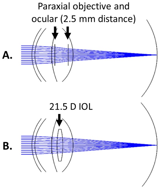
Schematic paraxial model to calculate dioptric power of the lenses of the telescope (upper figure) and the ray tracing model used as a reference to calculate relative magnification (lower figure).
We evaluated all the possible combinations of dioptric powers that produce a focused image with this corresponding magnification value. The results of this search are shown in Fig. 2 . Since the highest magnification values (about 13% in this configuration distance) were obtained when the objective lens has a dioptric power between 60 to 70 D, we limited our search to this range of powers, that also corresponded to similar ocular lens dioptric powers.
Fig. 2.
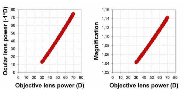
Possible combinations of objective (positive lens) and ocular (negative lens) lens powers that are able to form a posterior chamber intraocular telescope (left) with their corresponding magnification values (right).
As a starting point for an optimization procedure, we selected a + 66 D as an objective lens and a corresponding ocular lens of −66 D. Also, based on the power of the lenses, we fixed some physical parameters of the design, like the central thickness of the lenses (1.2 mm and 0.25 mm respectively). The initial shape factors of the lenses were nearly zero, both lenses had similar curvatures with opposite signs for the front and rear surfaces. The real distance from the apex of the posterior surface of the first lens to the anterior surface of the negative lens was set to 1.7 mm. In a capsular bag of 4 mm thickness, the anterior lens would be as close as possible to the iris plane and the posterior lens has very little room to moved backwards (moving only 0.2 mm backwards would make the lens lean on the posterior capsule). The optical zone of the first lens was set to a diameter of 5 mm while the second negative lens was 4 mm. The material selected was hydrophobic acrylic that allows a conventional cataract surgery implantation with micro-incision surgery.
In order to project the object onto a retinal area that is not damaged by AMD, or any other retinal disease, we induced a prismatic effect on the image. The decentration of the first lens shifted the retinal image along the direction of the decentration (Fig. 3 ) by 3.5° per mm of lens decentration. To induce a shift in the position of the central image and to avoid central vignetting with a pupil of 3 mm diameter, we selected a decentration value of 0.85 mm (corresponding to 3 degrees) as a fixed parameter in the design of the telescope. Although the used area in the retina depends on the particular patient, angles larger than 3 degrees corresponds to retinal locations with a sparse cone density and correspondingly a lower visual acuity.
Fig. 3.
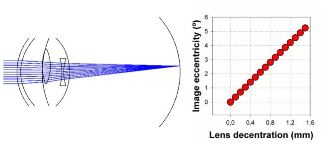
Displacing the positive lens of the telescope (left) induces a shift in the location of the image on the retina by 3.5° per mm of lens decentration (right).
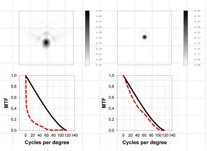
The optical configuration with decentered lenses induced significant off-axis aberrations. In particular, we estimated that a 2-D cylinder lens would be required to compensate for the induced astigmatism (at the 0.85 mm lens decentration) and, more importantly, the system would be affected by a significant amount of coma, over 1 μm for a 3 mm pupil diameter. Therefore, an optimization process was performed using the conic constants of the positive lens posterior surface and the negative lens anterior surface as variables. After the optimization, the optical quality of the system was nearly diffracted limited to show a high quality Point Spread Function (PSF) and Modulation Transfer Function (MTF), with Strehl ratio values over 0.8 (Fig. 4 ).
Fig. 4.
PSFs and MTFs (dashed red lines) before (left) and after (right) optimization of the telescope system that includes a 0.85 mm decentration value of the positive lens. Solid black lines represent the diffracted limit MTFs (MTFs are plotted here as the averaged of the horizontal and vertical profiles of the 2D MTFs).
3. Tolerance to lens position
The implantation of two lenses requires a very precise positioning to avoid large refractive errors after surgery. In this particular optical system, that uses very high power lenses, a small relative deviation from the nominal distances of the design can generate large errors in refraction. Taking the negative lens closer to the positive lens (distance smaller than the 1.7 mm nominal value) generates hyperopic refractions while a distance larger than 1.7 mm induces a myopic shift. Figure 5 shows the magnitude of these changes when the position of the negative lens is shifted with respect to the first positive lens. A displacement of 0.1 mm generates a significant refractive shift of 0.5 D.
Fig. 5.
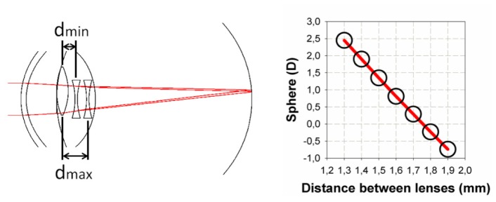
Tolerance to the relative position of the lenses. Changing the location of the negative lens with respect to the positive lens from 1.3 mm (dmin) to 1.9 (dmax) (diagram on the left) induces refractive errors in the retinal image (right) of 0.5 D per 0.1 mm.
To increase the tolerance to potential errors in the location of the lenses after surgery, we explored the possibility of including an aspheric coefficient (a conic constant k) to describe the posterior surface of the negative lens. A negative value of the conic constant generated positive spherical aberration (SA) in the eye (peripheral rays focused in front of central rays) that might allow for an extended visibility of the retinal image for a certain range of distances between the lenses. The cost of adding spherical aberration was a degradation of the image quality at the nominal distance (1.7 mm) such that a compromise between both factors was required.
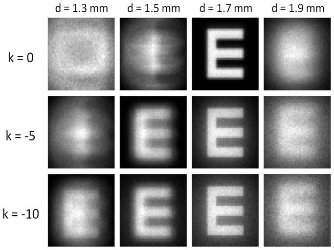
We selected the conic constant of the surface based on the contrast of a Snellen E optotype (0.4 decimal visual acuity as an arbitrary value) convolved with the monochromatic PSF. Figure 6 shows how the contrast between the fringes of the Snellen E was still visible for a selected k value of −10 (corresponding to a hyperbolic conic profile) in a range of lens distances from 1.3 to 1.9 mm. As expected, at the nominal distance (1.7 mm), the contrast in the optotype decreased compared to the cases where less SA was induced. But the contrast was still high enough to clearly distinguish the optotype and could be used as a compromise solution.
Fig. 6.
Snellen E optotype (decimal visual acuity 0.4) convolved with the PSF for different lens distances (1.3 mm to 1.9 mm; nominal is 1.7 mm) and different hyperbolic conic constants k of the negative lens posterior surface (the effect of this conic constant is to add positive spherical aberration).
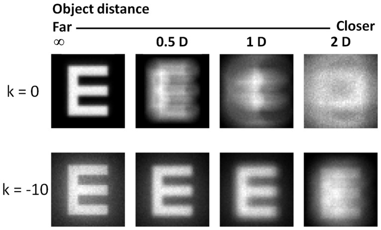
Adding positive SA may also be used to increase the depth of focus in the eye. In pseudophakic eyes, placing the object closer to the eye would mean that the refractive error becomes quickly hyperopic and the subject would require reading glasses to compensate for it. A very significant amount of positive spherical aberration like the one induced with our design, increases multifocality in the eye at the cost of decreasing optical quality in far distance vision. Figure 7 illustrates this principle for this particular intraocular telescope. Again, a Snellen E optotype (size 0.4 decimal visual acuity) was convolved with the PSF of the system and placed at different distances from the eye, from far (infinity) vision to 2 D (0.5 m). With the telescope free of SA, the contrast of the optotype would quickly require positive lenses to re-focus the object, but the additional spherical aberration also increases the range of object distances where the eye may not require additional corrections.
Fig. 7.
Snellen E optotype (decimal visual acuity 0.4) convolved with the PSF placed at different distances from the eye (Infinity to 2D) for the telescope without spherical aberration (k = 0 upper row) and the hyperbolic profile of the negative lens posterior surface (lower row, k = −10).
4. Astigmatism, axial length and higher order aberrations
Pre-existing corneal astigmatism and also that induced by the micro incision during surgery can potentially affect the image quality of the eye. But also residual defocus can still be present in the optical system after a bad adjustment of the optical power of the telescope with the optical power of the eye (cornea plus axial length). Both errors can be corrected with conventional spectacles after surgery, but the question that arises as to how tolerant the new telescopic lens is to these factors.
We performed a convolution of the previously used Snellen optotype (size was 0.4 decimal visual acuity) with the PSF of the modified (K = −10) system after adding a myopic cylinder in the vertical direction (this is the predominant direction of physiological astigmatism in the cornea) from 0 to 1.5 D in 0.25 steps. Additionally, we calculated the decrease in contrast through the optotype fringes (the E branches) as a function of the added astigmatic Diopters (Fig. 8 ). While at 0.75 Diopters of additional cylinder the E gaps were still visible (15% of contrast), at 1 D the contrast already fell under the 10% and at 1.5 D the E optotypes had practically no contrast through the branches.
Fig. 8.

(Upper) A snellen E optotype (0.4 visual acuity) was convolved with the PSF of the eye model plus additional astigmatism (up to 1.5 D of vertical cylinder). The contrast was estimated from the brightness through the dark and bright branches of the E´s (lower).
The tolerance to astigmatism would depend on the visual quality threshold. Since the potential users that would benefit from this implant are typically AMD patients with deteriorated visual acuity, the size of this letter can be a reasonable compromise. Under a 10% contrast (1 D cylinder) this letter would barely be visible. But over this limit, a cylinder of 0.5 D that corresponds to a contrast of 21% and even a cylinder of 0.75 D (with a 15% of contrast) would generate potentially visible letters.
Regarding the tolerance to defocus induced by a mismatch between the optical power of the implant and the optical power required to emmetropize the eye, we estimated the quality of the optotype in an eye with different axial lengths (same cornea model). In this case we observed that between ± 0.4 mm the E optotype remained visible with enough contrast in the gaps (>10%) (Fig. 9 ). In an emmetropic eye these shifts in axial lengths correspond to ± 1.3 D. The effect is an intrinsic consequence of this design that includes spherical aberration not only to increase the tolerance to the position of the lenses (Fig. 6) and to increase depth of focus (Fig. 7) but also to improve the tolerance to the potential differences in axial length in the different emmetropic eyes.
Fig. 9.

The 0.4 decimal visual acuity Snellen E optotype in an eye with different axial lengths (from shorter to longer eyes in a range of ± 0.4 mm).
Finally, in order to test the optical performance of the telescope on interaction with real aberrations (in this case aberrations are only those of the cornea) we built computational, individualized eye models for 10 subjects (mean age 51.5 years; standard deviation 5.1 years). Following previously established methods [15], we measured corneal topography (Atlas 9000, Carl Zeiss Meditec, Dublin CA, USA) and intraocular distances in the eye (Lenstar, Haag-Streit, Koeniz, Switzerland). The geometry of the exact corneal surface and the intraocular distances (axial length, anterior chamber depth and corneal thickness) were incorporated into the eye model with the telescope implanted instead of a crystalline lens. Each virtual model reproduces the ocular dimensions and aberrations (lower and higher orders) of the real eye as if the telescope had been implanted in the eye. For each model we calculated the radial averaged MTF (monochromatic λ = 550 nm) (Fig. 10 ; black thin lines) and compared this with the MTF of the model that was used to design the telescope with only radially symmetrical corneal aberrations (Fig. 10; red thick line). All subjects at the most visible frequencies were below this line.
Fig. 10.
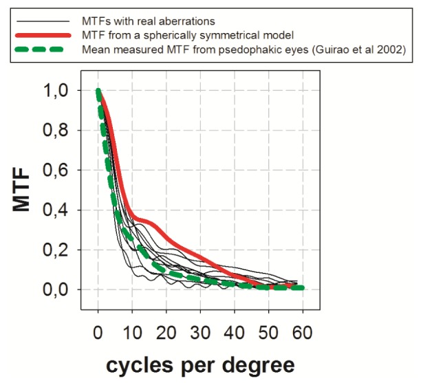
MTFs of 10 eye models implanted with the telescope that include all real aberrations (thin black lines) compared to an eye model with only spherically symmetrical aberrations (red) and to the mean measured MTF of a group of pseudophakic eyes implanted with monofocal IOLs.
We also compared the data with previously measured MTFs in pseudophakic eyes implanted with monofocal lenses (Fig. 10; dashed green) [16] showing very similar values to those calculated with the telescope. However, it should be noted that the mean measured MTF plotted in Fig. 10 came from an article published in 2002. The subjects included in that study had cataract surgery performed with relatively large corneal incisions. In modern cataract surgery with micro-incision, the MTF of pseudophakic eyes would probably be better than the MTFs calculated with the telescope, as expected when high values of spherical aberration are introduced into an optical system to increase the tolerance to others factors.
5. Discussion
We have designed a new intraocular telescope with aspheric surfaces to increase the tolerance to the position of the lenses. Since the dimensions of the lenses are relatively small they are made using a foldable material, the telescope can be implanted in the posterior chamber of the eye using micro incision cataract surgery (2.8 mm corneal incision) which greatly simplifies the surgical procedure. The anterior positive lens is designed to be located in the sulcus while the posterior negative lens is implanted in the capsular bag. The implantation of a version of the intraocular telescope following this concept has been recently described [17]. The design also has significant advantages in optical terms, such as the tolerance to different axial lengths and the increase in depth of focus. Regarding magnification (about 15%), we could not increase the size of the image as much as in previous (although consistently larger) devices, but on the other hand, this has the advantage of resulting in less aniseikonia when the device is implanted unilaterally. Furthermore, binocular summation would be expected to increase visual acuity beyond the values expected from the magnification effect. In fact, in a pilot study where this device was implanted in a group of AMD patients (with none or only minimal cataract), visual acuity was higher than the expected from the magnification values [17]. The telescope was designed with a nominal value of 1.7 mm distance between lenses but less distance between lenses can be tolerated. Up to a certain point (about 2D to 2.5 D) the subject might not need correcting spectacles. But if the distance between both lenses becomes too small, the eye will became hyperopic requiring positive correcting lenses. This kind of spectacle would also increase image magnification. Figure 11 illustrates this effect. The retinal image of a 0.4 decimal acuity Snellen E is shown on the right of the figure for a model eye implanted with a monofocal 21 D IOL (as a reference). The central letter corresponds to an eye implanted with the telescope at 1.7 mm distance between lenses (the nominal configuration) while the letter on the left corresponds to the telescope implanted with an inter-lens distance of 0.8 mm (this situation requires a correcting lens of + 4.5 D). In the last case magnification may be increased by up to 23% (even more with the use of a correcting lens with higher dioptric power). An increase in the distance between lenses generates the opposite effect (myopia), but it should be noted that this situation occurs less frequently than expected since the 1.7 mm real distance is the maximum distance possible. Larger distances would mean that the negative lens was touching or pushing the posterior capsule - this therefore represents a physical limit to the design.
Fig. 11.
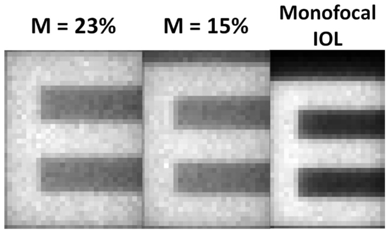
A 0.4 decimal acuity Snellen E optotype imaged through a model eye implanted with a monofocal IOL (right), implanted with the telescope with a 1.7 mm nominal distance between lenses (center) and with a 0.8 mm distance between lenses and corrected with a 4.5 D lens (left).
Another advantage to having the telescope implanted in the posterior chamber of the eye is that the field of view becomes larger compared to other devices. While the IMT can reach an instantaneous field-of-view between 6.6° and 9.2° depending on the configuration, this device approaches up to 20° without any vignetting effect in the field. This situation would preserve a large fraction of peripheral vision in the implanted eye and would presumably decrease the risk of having to use head movements to scan larger fields.
This telescope was initially designed for the emmetropic eye (intra ocular power of about 20 to 22 D) but is actually tolerant to a range of axial lengths (Fig. 9) such that it does not require a very accurate prediction of the intraocular lens power. If the power of the implant needs to be very low (myopes) or very high (hyperopes), however, it can be easily adapted by changing only the optical power of the first positive lens and keeping the posterior negative lens untouched to preserve all the original optical advantages.
In summary, we present a new intraocular telescope designed to overcome some of the limitations of previous devices (extended depth of focus and depth of field, tolerance to lens positions and to different eye’s geometries). It can be manufactured with dimensions and materials that facilitate surgical implantation without the need for the large corneal wounds and complications associated with other devices. This telescope is therefore a simple but promising device that can provide improved visual quality in AMD patients.
Acknowledgments
This research has been supported by London Eye Hospital Pharma (UK) and SEIDI, Spain, grant FIS2013-41237-R.
References and links
- 1.Peli E., “Vision multiplexing: an engineering approach to vision rehabilitation device development,” Optom. Vis. Sci. 78(5), 304–315 (2001). 10.1097/00006324-200105000-00014 [DOI] [PubMed] [Google Scholar]
- 2.Spitzberg L. A., Jose R. T., Kuether C. L., “Behind the lens telescope: a new concept in bioptics,” Optom. Vis. Sci. 66(9), 616–620 (1989). 10.1097/00006324-198909000-00008 [DOI] [PubMed] [Google Scholar]
- 3.Nguyen A., Nguyen A. T., Hemenger R. P., Williams D. R., “Resolution, field of view, and retinal illuminance of minituarized bioptics telescopes and their clinical significance,” J. Vis. Rehab. 7, 5–9 (1993). [Google Scholar]
- 4.Bailey I. L., “Critical view of an ocular telephoto system,” CLAO J. 13(4), 217–221 (1987). [PubMed] [Google Scholar]
- 5.Dallos J., “Contact glasses, the invisible eye glasses,” Arch. Ophthalmol. 15(4), 617–623 (1936). 10.1001/archopht.1936.00840160041003 [DOI] [Google Scholar]
- 6.Koziol J. E., Peyman G. A., Cionni R., Chou J. S., Portney V., Sun R., Trentacost D., “Evaluation and implantation of a teledioptric lens system for cataract and age-related macular degeneration,” Ophthalmic Surg. 25(10), 675–684 (1994). [PubMed] [Google Scholar]
- 7.Lipshitz I., Loewenstein A., Reingewirtz M., Lazar M., “An intraocular telescopic lens for macular degeneration,” Ophthalmic Surg. Lasers 28(6), 513–517 (1997). [PubMed] [Google Scholar]
- 8.Peli E., “The optical functional advantages of an intraocular low-vision telescope,” Optom. Vis. Sci. 79(4), 225–233 (2002). 10.1097/00006324-200204000-00009 [DOI] [PubMed] [Google Scholar]
- 9.Orzalesi N., Pierrottet C. O., Zenoni S., Savaresi C., “The IOL-Vip System: a double intraocular lens implant for visual rehabilitation of patients with macular disease,” Ophthalmology 114(5), 860–865 (2007). 10.1016/j.ophtha.2007.01.005 [DOI] [PubMed] [Google Scholar]
- 10.Amselem L., Diaz-Llopis M., Felipe A., Artigas J. M., Navea A., García-Delpech S., “Clinical magnification and residual refraction after implantation of a double intraocular lens system in patients with macular degeneration,” J. Cataract Refract. Surg. 34(9), 1571–1577 (2008). 10.1016/j.jcrs.2008.05.032 [DOI] [PubMed] [Google Scholar]
- 11.Felipe A., Artigas J. M., Gómez-Chova J., García-Delpech S., Díaz-Llopis M., “Magnification of the retinal image through an intraocular Galilean telescope,” J. Mod. Opt. 57(2), 152–158 (2010). 10.1080/09500340902912910 [DOI] [Google Scholar]
- 12.Agarwal A., Lipshitz I., Jacob S., Lamba M., Tiwari R., Kumar D. A., Agarwal A., “Mirror telescopic intraocular lens for age-related macular degeneration: design and preliminary clinical results of the Lipshitz macular implant,” J. Cataract Refract. Surg. 34(1), 87–94 (2008). 10.1016/j.jcrs.2007.08.031 [DOI] [PubMed] [Google Scholar]
- 13.Hudson H. L., Lane S. S., Heier J. S., Stulting R. D., Singerman L., Lichter P. R., Sternberg P., Chang D. F., IMT-002 Study Group , “Implantable miniature telescope for the treatment of visual acuity loss resulting from end-stage age-related macular degeneration: 1-Year Results,” Ophthalmology 113(11), 1987–2001 (2006). 10.1016/j.ophtha.2006.07.010 [DOI] [PubMed] [Google Scholar]
- 14.Liou H. L., Brennan N. A., “Anatomically accurate, finite model eye for optical modeling,” J. Opt. Soc. Am. A 14(8), 1684–1695 (1997). 10.1364/JOSAA.14.001684 [DOI] [PubMed] [Google Scholar]
- 15.Tabernero J., Piers P., Benito A., Redondo M., Artal P., “Predicting the optical performance of eyes implanted with IOLs to correct spherical aberration,” Invest. Ophthalmol. Vis. Sci. 47(10), 4651–4658 (2006). 10.1167/iovs.06-0444 [DOI] [PubMed] [Google Scholar]
- 16.Guirao A., Redondo M., Geraghty E., Piers P., Norrby S., Artal P., “Corneal optical aberrations and retinal image quality in patients in whom monofocal intraocular lenses were implanted,” Arch. Ophthalmol. 120(9), 1143–1151 (2002). 10.1001/archopht.120.9.1143 [DOI] [PubMed] [Google Scholar]
- 17.Qureshi M. A., Robbie S. J., Tabernero J., Artal P., “A novel, injectable intraocular telescope: a pilot study,” J. Cataract Refract. Surg. (2015). [DOI] [PubMed]


