Abstract.
Sinus blockages are a common reason for physician visits, affecting one out of seven people in the United States, and often require medical treatment. Diagnosis in the primary care setting is challenging because symptom criteria (via detailed clinical history) plus objective imaging [computed tomography (CT) or endoscopy] are recommended. Unfortunately, neither option is routinely available in primary care. We previously demonstrated that low-cost near-infrared (NIR) transillumination correlates with the bulk findings of sinus opacity measured by CT. We have upgraded the technology, but questions of source optimization, anatomical influence, and detection limits remain. In order to begin addressing these questions, we have modeled NIR light propagation inside a three-dimensional adult human head constructed via CT images using a mesh-based Monte Carlo algorithm (MMCLAB). In this application, the sinus itself, which when healthy is a void region (e.g., nonscattering), is the region of interest. We characterize the changes in detected intensity due to clear (i.e., healthy) versus blocked sinuses and the effect of illumination patterns. We ran simulations for two clinical cases and compared simulations with measurements. The simulations presented herein serve as a proof of concept that this approach could be used to understand contrast mechanisms and limitations of NIR sinus imaging.
Keywords: optical imaging, near-infrared medical instrumentation, chronic sinusitis, optical diagnosis, Monte Carlo simulation, void regions, point of care imaging
1. Introduction: Optical Imaging in the Maxillary Sinuses
1.1. Problem of Sinusitis
In the United States, approximately one in seven people develop sinusitis (sinus infections) each year, and 31 million cases of acute bacterial sinusitis become chronic and require extensive medical treatment. It has been estimated that nearly $6 billion/year is spent on all sinusitis-related cases.1 Chronic sinusitis generally evolves from a failure to accurately diagnose and treat acute cases. Primary care physicians are the first to diagnose and treat up to 87% of these cases.1 However, diagnosing acute sinusitis in primary care settings is challenging because the symptoms are nonspecific and often overlap with many other conditions such as migraines or other headaches, allergic rhinitis, and other upper respiratory infections. Sinusitis is common and diagnosis is best made via a detailed clinical history from a trained physician. Although guidelines for symptoms exist, they are difficult to enforce in practice, especially in the primary care setting. For this reason, symptomatic plus objective data are recommended to improve diagnosis, where objective data are obtained via radiographic or endoscopic imaging.2
The challenge of diagnosing adult sinusitis in the primary care setting has led to an overuse of plain radiographs (i.e., two-dimensional) and computed tomography [CT, i.e., three-dimensional (3-D)]. Conventional radiography is often used as a diagnostic measure but requires a radiologist’s reading and is not always available at the point of service (e.g., the primary care doctor’s office). Studies have found that the symptom-based diagnosis alone often leads to overtreatment3 and unnecessary clinical procedures. Symptoms alone do not necessarily correlate to disease detected by radiography4,5 and patient-based symptom reporting does not reliably correlate with CT findings.6 Konen et al. noted that the sensitivity and specificity of plain radiography in the diagnosis of maxillary sinus abnormalities were 67.7% and 87.6%, respectively, with CT serving as the gold standard.7 Due to its low sensitivity, a negative finding does not rule out sinusitis in many cases (). Although CT is the gold standard for ear, nose, and throat specialists, CT cannot be a practical solution for the primary care environment due to its cost and potentially unnecessary radiation exposure. The impact of sinusitis under-management will only worsen as the future strain on health care system reduces physicians’ time available for detailed patient examinations. For these reasons, there is a great need for a simple, low-cost office-based technique to aid in the diagnosis of sinusitis without the cost, inconvenience, or radiation risk of radiography or CT.
1.2. Optical Imaging in the Maxillary Sinuses
Optical imaging has been previously investigated as a means to detect sinus disease.1,8 Near-infrared light (NIR), particularly in the 850 nm spectral range, is well known to penetrate deeply into tissues, and conventional consumer-grade cameras have adequate sensitivity in this spectral range. We have shown that simple light-emitting diode (LED) light sources placed inside the mouth and low resolution consumer-grade cameras can image crude anatomical features of the adult maxillary sinus that compare well with the bulk findings of CT.1 Although the spatial resolution of the optical images was poor in relation to the CT, and specific anatomical features were obscured (e.g., thickness of the mucosa), the general features of the maxillary sinus such as high versus low opacity were clearly distinguished.
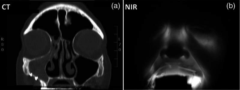
We have improved upon this design using upgraded light sources with higher power LEDs, improved light-tissue coupling and consumer-grade large-sensor digital cameras, while still maintaining a low-cost theme. A recent example of NIR optical imaging of the sinuses is provided in Fig. 1. A CT image slice of an adult subject is shown in Fig. 1(a). The bright white lines correspond to bone, the gray areas to soft tissues, and the black regions are air or nonturbid fluids (i.e., void regions). For this patient, the left maxillary sinus is clear, as evidenced by the thin lining around the dark (i.e., air-filled) maxillary sinus cavity just below the eyes. However, the right maxillary sinus presents a significant blockage (i.e., gray colored). The corresponding NIR image for this patient [Fig. 1(b)] demonstrates significant transmitted intensity differences between the right and left maxillary sinuses. For this image, an illuminator consisting of four compact LEDs (850 nm) was placed inside the mouth and pressed onto the hard palate in order to transilluminate the face. The picture was taken with an off-the-shelf digital camera with the IR blocking filter removed. Note that the NIR attenuation may be due to absorption or scattering debris and/or index of refraction changes (e.g., water versus air).
Fig. 1.
Example of near-infrared (NIR) optical imaging in the maxillary sinus. The patient presents a blocked right sinus as indicated in the computed tomography (CT) image slice (a). The patient’s left sinus is clear as shown by the thin white lining in the void region (black). The patient’s right sinus is completely filled (i.e., high opacity). The corresponding NIR image (b) mirrors the opacity of the CT image. The light source, composed of 850 nm LEDs, was placed inside the mouth to transilluminate the sinus. The bright aura around the mouth is due to source light leakage through the mouth area.
The image quality is significantly improved from our previous report.1 Although consumer-grade electronics continue to evolve, there will always be resolution/sensitivity limits based upon not only the diffuse nature of intense multiple scattering at NIR wavelengths, but also the complexity of the anatomy. An understanding of the relationship between the detected image, anatomical features, and NIR illumination patterns is lacking.
1.3. Light Propagation Modeling in the Human Head
In order to better understand contrast origins of NIR optical imaging in the sinuses, we have modeled the propagation of NIR photons inside the adult human head. Our primary focus is to simulate what the camera detects by capturing photons that enter the head through the hard palate and exit through the face. Modeling light propagation in the human head is a challenging task because of both anatomic complexity and void regions. Simple models (e.g., semi-infinite or two layer models) would fail to capture the high degree of anatomical complexity of the human head, particularly in the facial regions. For this reason, mesh-based approaches are preferred in order to capture the anatomical complexity presented by conventional structural images (e.g., CT, MRI). Several mesh-based solvers exist, both commercial and academic, that can import 3-D anatomical images and model NIR light propagation. Diffusion theory is widely implemented in mesh-based light transport modeling due to its relative simplicity and ability to capture the macroscopic features of NIR light propagation.
However, void regions (i.e., regions without significant optical light scattering) present a challenge for NIR modeling with diffusion theory. The problem with void regions is that they fail to satisfy key tenets of diffusion theory, namely that the photon fluence must be quasi-isotropic (i.e., far from sources and boundaries) and that scattering must be significantly greater than absorption. Void regions are poorly modeled by diffusive NIR light transport models. Studies have noted some significant disagreements between diffusion theory and transport-based models that properly account for void or low-scattering regions.9–11 For the case of sinus imaging, a clear sinus would be air-filled, and thus will have null scattering. Some have implemented diffusion theory in nonscattering regions by assigning very low-scattering coefficients () to the void regions (e.g., cerebral spinal fluid layer).12 Hybrid models combine diffusion theory to calculate bulk-features of the light transport with ray-tracing to propagate photons in the void regions.11,13–15 Transport theory, from which diffusion theory is derived, is a more generally accurate means to model NIR light transport in complex systems.16,17 Monte Carlo methods, particularly with transport-based engines, can also be applied.
We note that several research groups have determined the influence of the frontal sinus on measurements of the brain in the prefrontal cortex.18–24 In these cases, the sinus is something to be avoided because it affects the measurement of frontal lobe hemodynamics. However, in the case of sinus imaging, the void region is the source of the contrast. Specifically, we need to know the extent and contents of the void region.
1.4. Goal of this Study
The goal of this study was to produce simulations of NIR light transport in the adult human head in order to understand the sensitivity of the optical imaging method applied to the maxillary sinuses. For example, if a small NIR intensity difference was observed between the right and left sinuses, how reliably could this indicate the presence of sinus disease? What effect might the configuration of the light sources in the illuminator have upon the detected image? Can the features commonly observed in the clinic be understood in terms of the anatomy of the head? A reliable model of light transport in the adult human head could be used to help answer these questions. We will demonstrate how this Monte Carlo approach could be used to answer all of these questions by providing proof-of-concept results.
2. Materials and Methods
2.1. CT Scans of the Head
A list of the patients sampled for this study is provided in Table 1. In order to serve as a control/standard for simulations, we used the publically available male data set (“Adam”) from the visible human project (see Ref. 25; written permission was obtained from the National Library of Medicine). The CT data set of the head feature 1 mm slices with (12-bit grayscale), thus providing adequate sampling of the anatomy. Coronal CT images were selected. We also used other representative data (patients #2 and #3) from our on-going clinical study. These patients provided written informed consent to provide their CT images and participate in the NIR imaging study. The CT scans for these patients were similar but with fewer slices.
Table 1.
List of adult patients simulated in this study.
| State of sinuses | CT scan | |
|---|---|---|
| Patient #1 | Presumed normal | 1 mm slices, 245 coronal |
| Patient #2 | Advanced sinusitis | 96, coronal |
| Patient #3 | Mild sinusitis | 192, coronal |
2.2. Generation of Anatomical Mesh
Image segmentation and mesh creation were performed using the version 1.12 “Nirview” tool.26,27,28 Once the CT images were loaded and the distances/lengths were entered, three different regions (bone, soft tissues, and sinuses) were assigned based upon the differences in image intensity. Nirview was used to initiate the segmentation, which was subsequently manually adjusted to improve continuity. Only the front half of the head was considered in the rendered volume. The entire head anatomy was not needed as the majority of photons of interest will be confined to the facial areas (i.e., we are not interested in the brain or the back of the head). The anatomical mesh was then generated using nodes and tetrahedral elements. Region labels were recorded for each element.
Optical properties were assigned to each region. We assigned values of absorption (, ), scattering (, ), scattering anisotropy (), and index of refraction () to each region. The reduced scattering was defined as . We do not anticipate sensitivity to in soft tissues, thus a “standard” value of 0.9 was used. Optical properties near 850 nm assumed for these simulations are provided in Table 2.
Table 2.
Estimated optical properties at 850 nm for each tissue region in CT image.
| Region | () | () | ||
|---|---|---|---|---|
| Bone | 0.005 | 15 | 0.9 | 1.5 |
| Soft tissue | 0.01 | 10 | 0.9 | 1.37 |
| Sinus (clear) | 0 | 0 | 0 | 1 |
2.3. Mesh Monte Carlo
Light transport in the anatomical model was simulated using the open source tetrahedral mesh-based Monte Carlo package “MMCLAB.”29,30 The MMCLAB code was interfaced through MATLAB. For adequate sampling, a minimum of photons were used, although most simulations used photons. Source positions were manually added into the mesh. Because only a single light source could be used for each simulation, serial simulations were added together in order to simulate arrays of sources. Thus, the total number of photons launched in multisource configurations was actually times the number of sources unless otherwise specified. In order to simulate the detection of photons by a camera taking a picture of the face, we counted photons that crossed the face surface as “detected.” We did not consider photon exit angles, but note that in clinic, the camera is fairly close to the face (18 in.). Detected photons escape via the face and were assumed to be detected with perfect efficiency. The photon count maps on the mesh surface were linearly interpolated to produce smoother images.
2.4. Clinical Prototype
The clinical imaging setup has been previously reported.1 Briefly, a probe with embedded LEDs (4 in an X-style pattern, 850 nm) was inserted into the mouth. The new probe is soft and pliable and is able to fit into the contour of the upper palate of the mouth. The entire probe is covered in a polyethylene bag to serve as a barrier for infection control. Once activated, the LED illuminates for 3 s, during which time the camera takes a picture of the face at three different exposure times. The camera is a standard off-the-shelf digital SLR camera (Cannon EOS Rebel T3), with the IR-blocking filter manually removed. The camera was focused on the face, at a fixed distance of 18 in. Images from the red channel were used in this study—very few differences were observed between red, blue and green channels for detection at 850 nm. Further details about the imaging setup, as well as an analysis of over 100 patients will be presented in a forthcoming article.
3. Results
3.1. Light Transmission in Healthy Adult Subject
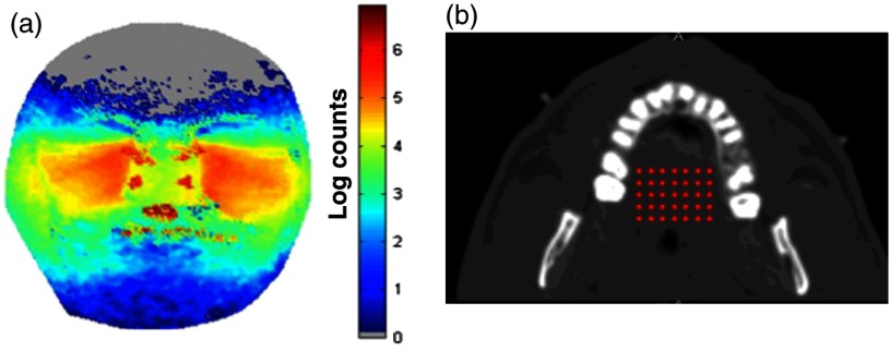
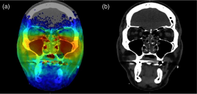
Figure 2 provides a typical result of the simulations for a presumed clear sinus in patient #1 (visible human subject, Adam). Figure 2(a) provides the results of a simulation using the optical properties of Table 2. The virtual light sources were simulated by placing a series of individual light sources in a onto the hard palate, as shown using the transverse CT image of the mouth [Fig. 2(b)]. The light was modeled to propagate up into the head in a fashion similar to the clinical prototypes we have tested. The color corresponds to the logarithm of the number of photons exiting a given location on the face at a given location (scale bar on the right). We note that the simulation was run 35 times (one per source), each with photons. As an anatomical reference, we also provide an overlay of the detected photon distribution [Fig. 2(a)] onto a representative coronal CT image in Fig. 3.
Fig. 2.
Representative Monte Carlo simulations of exiting photons through the three-dimensional (3-D)-generated mesh generated from CT data (a). In this geometry, an array of light sources (red dots) was placed onto the hard palate (b) as indicated in the transverse CT image. Each source (red dot) was considered to have equal strength ( location).
Fig. 3.
Overlay of the detected photon counts onto a coronal CT slice of patient #1 (a). The CT image alone is provided as a reference (b).
From inspection of the CT image (slice #94), the maxillary sinus is generally clear (i.e., air-filled) and presumed normal. The modeled photon overlay (Fig. 3) reveals that the majority of detected photons have exited from the cheek area over the maxillary sinus. We have observed similar NIR patterns of illumination in the clinical NIR images of healthy, clear sinuses. The distribution of escaping photons in the cheek area is mainly symmetric; the brightest intensity is generally under the eyes and along the nose. There are a few intensity bright spots at locations in the image. For example, a few bright spots in the nasal area also correspond to small dark regions in the CT image. The nose and mouth are also air-filled cavities and do not strongly attenuate the light. However, there are also bright spots in the upper corners of the nose by the eyes. These spots may be evidence of sampling the ethmoid sinuses, which are network of small cavities between the eyes and nose. We also investigated the effects of changing the tissue optical properties (absorption and reduced scattering) in two different ways. First, we changed the bulk optical properties of the tissue constituents (e.g., bone) to estimate their impact on the final transillumination images. In other words, we changed the value of soft tissue absorption. Second, we spatially altered the optical properties (i.e., absorption and reduced scattering) of the tissue constituents according to a Gaussian distribution, rather than assume a single value for each tissue constituent. In other words, the value of the optical property in a given tissue component (e.g., bone scattering) was not assumed to be the same throughout, but rather it was varied throughout the region. In both cases we varied the absorption and scattering of the tissue constituents by about 20%, but found that the impact of changing the optical properties on the transillumination images were minimal (e.g., the original findings in the images were not altered by the change in optical properties).
3.2. Effect of Blocked Sinus (Simulated)
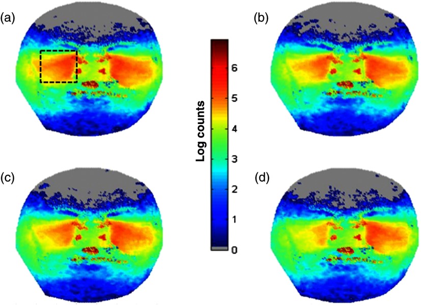
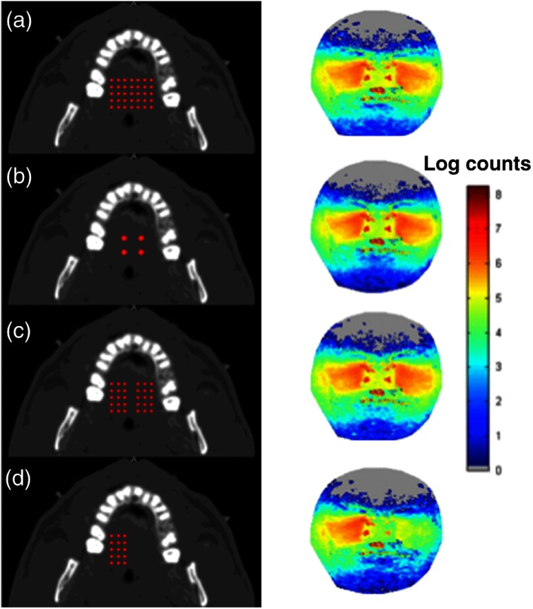
We can now predict what happens to the NIR images as the condition of the maxillary sinuses progresses away from a normal, clear state. Figure 4 demonstrates the effect of anatomical variations in the patient’s right maxillary sinus. All simulations are provided with the same count scale. Figure 4(a) is the normal case provided as a reference from Fig. 2, where the sinuses were filled with air. In Fig. 4(b), we added water to completely fill the right maxillary sinus cavity (, , ). The result is diminished light transmission through the right sinus, compared to the left air-filled sinus. In Fig. 4(c), we removed the water and thickened the mucosal layer of the right maxillary sinus (, , , 2-mm thickness). The mucosal thickening reduces the detected intensity with respect to the completely air-filled left maxillary sinus. Although the number of detected photons is lower, water-filled and mucosal thickening have similar image features [Figs. 4(b) and 4(c), respectively]. In Fig. 4(d), we removed the mucosal thickening and added water with a small amount of scattering (, , ) to simulate debris in the sinus fluid. A further reduction in detected photons is the result.
Fig. 4.
Effect of blocked sinuses simulated in the “Adam” patient of the visible human project (patient #1). (a) The “normal” case as presented in Fig. 2. (b) Simulates a water-filled sinus. (c) Simulates increased mucosal thickening of an otherwise air-filled sinus. (d) Simulates a water plus debris-filled sinus with normal mucosal thickening. The dashed box in (a) is the approximate region of the sinus to be analyzed further in the next figure. See the text for details.
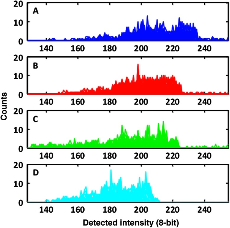
Alteration of the size and contents of the sinus affects the detected spatial distribution of light in the simulation. Figure 5 provides a histogram of the light detected from the right sinus for the previously simulated manipulations of Fig. 4. We took the simulation images of light exiting the face from Fig. 4 and converted them into a grayscale image (8 bit). In this way, we simulate what the camera would detect in the clinic given the four cases represented in Fig. 4. We then calculated a histogram from the boxed region outlined in Fig. 4(a). In this case, we plot the number of effective pixels with a given intensity value (with a bin width of 1). Subsequent panels are the histograms of the same boxed anatomical area for the other cases presented in Fig. 4. We note that with each change to the sinus, the distribution of the signal histogram within the region of interest also changes. Water [Fig. 4(b)] has a small effect on the histogram, mainly reducing the high count areas. Mucosal thickening [Fig. 4(c)] results in a small shift of the histogram center, with a larger energy focused in the lower count regions than the reference in Fig. 4(a). Liquid and debris [Fig. 4(d)] further shift the histogram mean to lower signal levels. Note that for each case, the selected anatomical area used for the histogram was the same.
Fig. 5.
Histograms of the simulated changes in sinus cavity material provided in Fig. 4. Each simulation was converted into an 8-bit grayscale image. A histogram of the right sinus (indicated by the boxed area) is provided for each of the four cases. The mean and distribution of the histogram changes each time as the volume and contents of the sinus are changed.
3.3. Effect of Source Placement
Although consistent illumination over the entire hard palate may be desired, it is not necessarily practical to implement in the clinic as it requires many LEDs along with increased power requirements. For this reason, we simulated several different source configurations to gain insight about the effect of source patterns on the detected NIR optical signals. Figure 6 provides four different source configurations for the healthy version of patient #1. Figure 6(a) is replicated from Fig. 2 as a reference, using a array of 850 nm light sources, each with . In Fig. 6(b), we replace the array with a high power array of equivalent total optical power, with each source at intensity . The simulated images are similar, although the signal is slightly weaker, especially near the edges of the sinus away from the nose. In Fig. 6(c), we remove the center line of sources in the array of Fig. 6(a). Although each source maintains , the overall image is fairly similar to Fig. 6(a). This configuration was presented due to our clinical observation that illuminating mainly in the center of the palate tended to diminish image quality; from the simulation, we note that the center line is not needed. Finally, in Fig. 6(d), we restrict the light sources to only one side using a array of sources each with . The right side of the image is similar to the previous images; however, as anticipated, the left sinus illumination is greatly diminished. We note the strong diffusive nature of the NIR light as some intensity manages to migrate to the left side of the head.
Fig. 6.
Effect of source placement in patient #1. (a) Simulates an array of 35 light sources of equal intensity (). (b) Simulates a smaller four source array but of nearly the same total intensity (). (c) The removal of the center line of sources from the array in (a) without changing the intensity (still ). (d) Further removes sources to illuminate only one side (still ) using a array.
3.4. Advanced Case of Sinusitis: Simulation and Comparison With Clinical Data
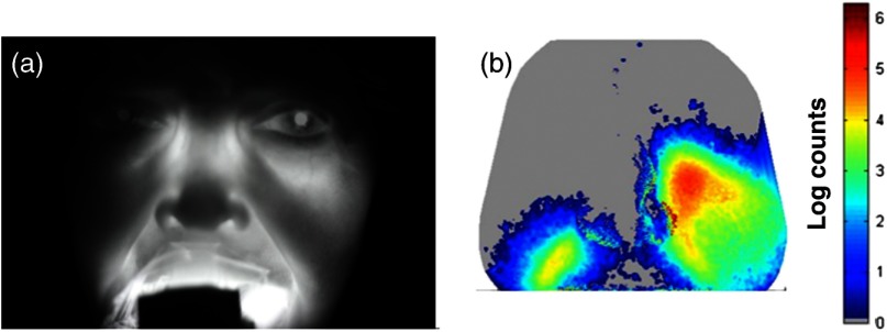
Figure 7 compares the NIR clinical image with a simulation using the CT scans for patient #2. Note that a representative CT slice was presented in Fig. 1. The illumination pattern was similar to the case in Fig. 6(b) ( array) for simulation and measurement. The simulation shows conclusively minimal light penetration in the right maxillary sinus and significantly lower opacity in the patient’s left sinus.
Fig. 7.
Computer simulation using 3-D CT scan and Monte Carlo model compared to experiment for a case of advanced sinusitis. The CT image for patient #2 is provided in Fig. 1 and reveals that the right maxillary sinus is completely blocked. The high opacity of the sinus is evident in the NIR image of the patient (a). Using the patient’s 3-D CT scan slices, we simulate what the clinical image should look like in (b). The main features of the image (low opacity on left, high opacity on right) are clearly visible. In this case, the illumination of the region near the ethmoid sinuses is not visible in the simulation.
3.5. Mild Case of Sinusitis
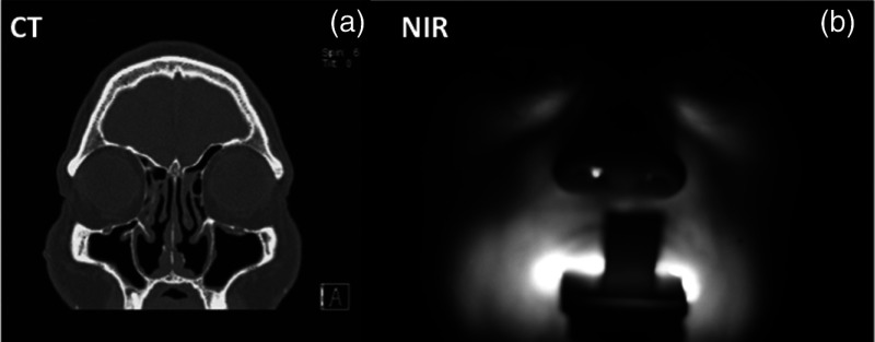
Patient #3 was clinically diagnosed with a mild case of sinusitis. Figure 8 provides a CT image slice (a) compared to the NIR image (b). Inspection of the CT shows a slight mucosal thickening in both maxillary sinuses, with a smaller cavity volume on the right side (about a 30% smaller air volume as determined from a 3-D analysis). At first glance, the NIR image is unremarkable. However, a quantitative analysis of the NIR illumination image of the two sinuses shows a small but detectible reduction in intensity on the right versus the left side. A natural question is to ask if the unequal intensity is a product of the patient’s anatomy or a product of variance in the measurement itself. Both sinuses are clear of fluid, though evidence of mucosal thickening is present. Compared to the previous patient, the sinus cavity is significantly less attenuating.
Fig. 8.
Patient #3 with representative CT slice (a) and NIR image (b). Note that the patient’s right sinus cavity is slightly smaller in volume due to the thickening of the membranes observed near the bottom of the right maxillary sinus cavity.
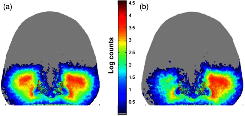
The Monte Carlo simulation clearly demonstrates that the patient’s anatomy on the right side is sufficiently perturbed to produce asymmetrical NIR illumination patterns. Figure 9 demonstrates the similarity between CT and NIR images (both experimental and simulated). The lower NIR signal on the patient’s right sinus originates from a smaller air volume on that side. Given that sinus volume varies, it is not evident that such a small change could be detected in absolute terms as it would be for CT imaging. We also observe that the light signal near the nose captured in the NIR image also appears in the simulation. The source configuration presented in Fig. 6(b) was again used for both simulation and experiment. Figure 6(a) is the forward simulation for patient #3 using the 3-D CT images for the patient. Both sides demonstrate relatively low opacity, but the intensity is clearly lower (smaller spatial extent) on the right side as opposed to the left, in agreement with the NIR and CT images. Further, to demonstrate the sensitivity of the NIR imaging to mucosal thickening (or sinus volume), we augmented the CT images by increasing the mucosal thickening by another (estimated) 3 mm. Note that the intensity on the right side continues to decrease [Fig. 6(b)].
Fig. 9.
Simulations showing progression of sinus disease. (a) The simulation of the case corresponding to the clinical image of patient #3 (Fig. 8). (b) A simulation of further disease progression where we increased mucosal thickening by an additional 3 mm. Note that the trend of asymmetry continues and becomes significantly visible with increased mucosal thickening. Light attenuation increases as a result of the reduced air volume in the sinus due to mucosal thickening.
4. Discussion
The general experimental character of our clinical measurements can be reproduced using Monte Carlo simulations. We have previously shown that low-cost consumer-grade equipment (LED light sources and cameras) offers sufficient sensitivity to qualitatively image sinus opacity in general agreement with CT imaging.1 We have improved the application of diffuse optical imaging to the sinuses by upgrading to cameras with a larger imaging area and more pixels, implementing more compact and brighter LED light sources, improving optical coupling of light into the palate (via improved illuminator designs), and by using digital image processing with standardized imaging protocols. These advances have improved the quality of our data; however, the limits of the technique have not been addressed, particularly related to the contrast originating from anatomic and physiologic variations manifested over a broad spectrum of the disease state. The general observation that the volume of air in the sinus is the main source of contrast in the NIR images was observed in the simulations.
Monte Carlo modeling of the light is a strong first step toward understanding the origins of contrast and limits of the diffuse optical imaging technique applied to the sinuses. In this preliminary modeling study, we demonstrated that clear sinus volume (e.g., air-filled) is a significant contributor to the character of the transillumination image. Detected intensity differences between right and left sides of the face largely depend upon the volume of clear sinus. The air-filled sinus dramatically reduces photon path length due to a lack of scattering. Air offers little attenuation to NIR photons (i.e., negligible scattering and absorption); thus an air-filled sinus will redirect photon paths (due to the index mismatch with respect to tissues) but the attenuation compared to bone and soft tissue is negligible. Reduced attenuation allows for a greater probability for the light to exit through the face, especially where the bone is thinnest near the eyes. Very few detected photons sample blocked sinuses (high opacity), especially if the sinus is filled with scattering debris that increases optical attenuation. Even relatively minor changes in the optical properties of the sinus cavity can be detected via transillumination; water-filled versus air-filled, and modest mucosal thickening (which changes the sinus air volume) both attenuate light significantly enough to be distinguished from normal air-filled sinus conditions. We emphasize that these simulations do not prove that these subtle changes in mucosal thickening can be detected in all patients and situations. Rather, it is important to note that small changes in sinus derived from mucosal thickening can be detected by measurement of transillumination asymmetry (right versus left) using low-grade imaging hardware. Variations in optical properties did not reproduce the disease states observed in the clinical images. For example, using a distribution of absorption and scattering values in the bone and soft tissues did not create significant asymmetry between the right and left sides.
The Monte Carlo simulations provide a way to optimize illumination patterns of the hard palate. From an engineering perspective, this is important so that a large number of designs can be tested without significant expense. For example, we have observed that illumination along the center line of the palate was not sensitive to the sinus volume. Our simulations support this finding; there were minor differences between broad discrete illumination and removal of light sources along the center line of the hard palate [Figs. 6(a) and 6(c), respectively]. Because of this finding, subsequent designs did not require light sources along the center line and this helped to improve our illuminator with more flexible designs. Creating a flexible illuminator is very important because good coupling between the light sources and the hard palate is essential; asymmetry in the illumination pattern might be interpreted as a change in sinus volume. We have simulated the effect of shifting the probe inside the palate. For example, if we move the four source probe [Fig. 6(b)] a few millimeters to the left, we discover that the intensity of the detected light indeed changes, but that the spatial characteristics of the detected light are much less affected (not shown). These simulations show that small changes in probe location do not adversely affect the diagnosis; however, more detailed quantitative analysis is needed to determine the effects of probe placement and design on diagnostic sensitivity and specificity.
The simulations further suggest that continuous broad spatial illumination may not be necessary; well-designed spatial placement of a few bright LEDs can provide equivalent illumination to sample the sinuses. In the simulations, we showed that for an equivalent total optical power, four LEDs achieved similar sensitivity to the sinuses as a spatially broad pattern of 35 LEDs [Fig. 6(b)]. This finding is important for designing the optimal and practical LED illuminator for clinical use. Our simulation results support a design that employs a few high-power LEDs placed laterally away from the center of the mouth. Other source combinations, including timing and spatial patterns in the light sources can be modeled. This modeling study can also be used to determine if tomographic approaches to sinus imaging could enhance the detection of anatomic and physiologic changes arising from sinus infections.
Although promising, this study is subject to several limitations. We have assumed only the minimum number of tissue layers (soft versus hard) in the CT image segmentation. Soft tissues were lumped together (e.g., skin, fat, muscle) for simplification. Each of these tissue regions vary in the absorption, scattering, scattering anisotropy, and index of refraction. Tissue regions were all considered homogeneous; clearly some variation in these optical properties is expected and these local variations may diminish sensitivity to more subtle stages of sinus disease and create “normal” asymmetry. We found that varying tissue optical properties (absorption and scattering) about 10% to 20% could not mimic the diseased state seen in our images. We did not consider patient motion/breathing effects as the measurements themselves typically are taken in . We did not consider the optics of light after exiting the tissue (e.g., effects of camera lenses, photon exit angle). We also did not consider the effects of anisotropic scattering. We only modeled a single wavelength, 850 nm, which was clinically chosen as a compromise between low tissue attenuation, camera detection sensitivity, and commercial availability. The case studies selected were not blinded.
Future work will expand to variations in the optical properties and anatomy to better assess the typical range of “normal” values seen in healthy subjects. We plan to perform simulations using exact features extracted from CT images (sinus volume, bone thickness, distances) and compare them to the features of the NIR images. Through accumulation of multiple patient data, we will be able to optimize the Monte Carlo simulation parameters as well as relate the light attenuation to different anatomic and physiologic patient features. We also intend to extend this imaging and modeling concept into the pediatric sinuses; modeling for the pediatric population is particularly important and challenging because CT imaging is less frequently prescribed in pediatric sinusitis cases and their sinuses are still going through anatomic changes through late teenage years.
5. Conclusion
Monte Carlo simulations of NIR light transport in the adult human head demonstrate that the low-cost optical detection of sinus disease is clinically feasible. We observed that NIR forward simulations with Monte Carlo and 3-D meshes generated via CT agreed favorably with clinical measurements in two representative case studies, one with an extreme maxillary sinus blockage and one with subtle mucosal thickening. The simulations may be used to study the effects of illumination and detection variables and guide the design of clinical technology.
Acknowledgments
This work was supported by the National Institutes of Health under Grants P41EB015890-33 (Laser Microbeam and Medical Program: LAMMP) and R44-DC012018-01SBIR. BLI programmatic support from the Beckman Foundation is acknowledged. We thank James Kim and Sean Ison for their assistance in patient data collection and Janaka Ranasinghesagara for his crucial assistance with surveying potential Monte Carlo simulations. We also thank Kevin Yang for contributing to this project idea after constructing adult head sinus phantoms to simulate light transport. Our thanks also go to the patients who volunteered for this study and the National Library of Medicine for the use of the visible human data set.
Biography
Biographies of all the authors are not available.
References
- 1.Mahmood U., et al. , “Near-infrared imaging of the sinuses: preliminary evaluation of a new technology for diagnosing maxillary sinusitis,” J. Biomed. Opt. 15, 036011 (2010). 10.1117/1.3431718 [DOI] [PMC free article] [PubMed] [Google Scholar]
- 2.Rosenfeld R. M., et al. , “Clinical practice guideline: adult sinusitis,” Otolaryngol. Head Neck Surg. 137, S1–31 (2007). 10.1016/j.otohns.2007.06.726 [DOI] [PubMed] [Google Scholar]
- 3.Stankiewicz J. A., Chow J. M., “A diagnostic dilemma for chronic rhinosinusitis: definition accuracy and validity,” Am. J. Rhinol. 16, 199–202 (2002). [PubMed] [Google Scholar]
- 4.Bhattacharyya N., “Clinical and symptom criteria for the accurate diagnosis of chronic rhinosinusitis,” Laryngoscope 116, 1–22 (2006). 10.1097/01.mlg.0000224508.59725.19 [DOI] [PubMed] [Google Scholar]
- 5.Kenny T. J., et al. , “Prospective analysis of sinus symptoms and correlation with paranasal computed tomography scan,” Otolaryngol. Head Neck Surg. 125, 40–43 (2001). 10.1067/mhn.2001.116779 [DOI] [PubMed] [Google Scholar]
- 6.Bhattacharyya T., Piccirillo J., Wippold F. J., II, “Relationship between patient-based descriptions of sinusitis and paranasal sinus computed tomographic findings,” Arch. Otolaryngol. Head Neck Surg. 123, 1189–1192 (1997). 10.1001/archotol.1997.01900110039006 [DOI] [PubMed] [Google Scholar]
- 7.Konen E., et al. , “The value of the occipitomental (Waters’) view in diagnosis of sinusitis: a comparative study with computed tomography,” Clin. Radiol. 55, 856–860 (2000). 10.1053/crad.2000.0550 [DOI] [PubMed] [Google Scholar]
- 8.Mansfield C. D., Attas E. M., Gall R. M., “Evaluation of static thermal and near-infrared hyperspectral imaging for the diagnosis of acute maxillary rhinosinusitis,” J. Otolaryngol. 34, 99–108 (2005). 10.2310/7070.2005.04056 [DOI] [PubMed] [Google Scholar]
- 9.Aydin E. D., de Oliveira C. R., Goddard A. J., “A comparison between transport and diffusion calculations using a finite element-spherical harmonics radiation transport method,” Med. Phys. 29, 2013–2023 (2002). 10.1118/1.1500404 [DOI] [PubMed] [Google Scholar]
- 10.Hielscher A. H., Alcouffe R. E., Barbour R. L., “Comparison of finite-difference transport and diffusion calculations for photon migration in homogeneous and heterogeneous tissues,” Phys. Med. Biol. 43, 1285 (1998). 10.1088/0031-9155/43/5/017 [DOI] [PubMed] [Google Scholar]
- 11.Hayashi T., Kashio Y., Okada E., “Hybrid Monte Carlo-diffusion method for light propagation in tissue with a low-scattering region,” Appl. Opt. 42, 2888–2896 (2003). 10.1364/AO.42.002888 [DOI] [PubMed] [Google Scholar]
- 12.Custo A., et al. , “Effective scattering coefficient of the cerebral spinal fluid in adult head models for diffuse optical imaging,” Appl. Opt. 45, 4747–4755 (2006). 10.1364/AO.45.004747 [DOI] [PubMed] [Google Scholar]
- 13.Arridge S. R., et al. , “The finite element model for the propagation of light in scattering media: a direct method for domains with nonscattering regions,” Med. Phys. 27, 252–264 (2000). 10.1118/1.598868 [DOI] [PubMed] [Google Scholar]
- 14.Tarvainen T., et al. , “Coupled radiative transfer equation and diffusion approximation model for photon migration in turbid medium with low-scattering and non-scattering regions,” Phys. Med. Biol. 50, 4913 (2005). 10.1088/0031-9155/50/20/011 [DOI] [PubMed] [Google Scholar]
- 15.Yang D., et al. , “Light transport in turbid media with non-scattering, low-scattering and high absorption heterogeneities based on hybrid simplified spherical harmonics with radiosity model,” Biomed. Opt. Express 4, 2209–2223 (2013). 10.1364/BOE.4.002209 [DOI] [PMC free article] [PubMed] [Google Scholar]
- 16.Klose A. D., Hielscher A. H., “Optical tomography using the time-independent equation of radiative transfer—Part 2: inverse model,” J. Quant. Spectrosc. Radiat. Transfer 72, 715–732 (2002). 10.1016/S0022-4073(01)00151-0 [DOI] [Google Scholar]
- 17.Klose A. D., et al. , “Optical tomography using the time-independent equation of radiative transfer—Part 1: forward model,” J. Quant. Spectrosc. Radiat. Transfer 72, 691–713 (2002). 10.1016/S0022-4073(01)00150-9 [DOI] [Google Scholar]
- 18.Dehghani H., et al. , “Optical tomography in the presence of void regions,” J. Opt. Soc. Am. A 17, 1659–1670 (2000). 10.1364/JOSAA.17.001659 [DOI] [PubMed] [Google Scholar]
- 19.Koyama T., et al. , “Practical and adequate approach to modeling light propagation in an adult head with low-scattering regions by use of diffusion theory,” Appl. Opt. 44, 2094–2103 (2005). 10.1364/AO.44.002094 [DOI] [PubMed] [Google Scholar]
- 20.Hoshi Y., et al. , “Reevaluation of near-infrared light propagation in the adult human head: implications for functional near-infrared spectroscopy,” J. Biomed. Opt. 10, 064032 (2005). 10.1117/1.2142325 [DOI] [PubMed] [Google Scholar]
- 21.Li T., Gong H., Luo Q., “Visualization of light propagation in visible Chinese human head for functional near-infrared spectroscopy,” J. Biomed. Opt. 16, 045001 (2011). 10.1117/1.3567085 [DOI] [PubMed] [Google Scholar]
- 22.Tanifuji T., et al. , “Finite-difference time-domain analysis of time-resolved reflectance from an adult head model composed of multilayered slabs with a nonscattering layer,” Appl. Opt. 51, 429–438 (2012). 10.1364/AO.51.000429 [DOI] [PubMed] [Google Scholar]
- 23.Kurihara K., et al. , “The influence of frontal sinus in brain activation measurements by near-infrared spectroscopy analyzed by realistic head models,” Biomed. Opt. Express 3, 2121–2130 (2012). 10.1364/BOE.3.002121 [DOI] [PMC free article] [PubMed] [Google Scholar]
- 24.Dehaes M., et al. , “Quantitative effect of the neonatal fontanel on synthetic near infrared spectroscopy measurements,” Hum. Brain Mapp. 34, 878–889 (2013). 10.1002/hbm.v34.4 [DOI] [PMC free article] [PubMed] [Google Scholar]
- 25.Visible Human Project, http://www.nlm.nih.gov/research/visible/visible_human.html (2014).
- 26.Jermyn M., et al. , “Fast segmentation and high-quality three-dimensional volume mesh creation from medical images for diffuse optical tomography,” J. Biomed. Opt. 18, 086007 (2013). 10.1117/1.JBO.18.8.086007 [DOI] [PMC free article] [PubMed] [Google Scholar]
- 27.Dehghani H., et al. , “Near infrared optical tomography using NIRFAST: algorithm for numerical model and image reconstruction,” Commun. Numer. Methods Eng. 25(6), 711–732 (2008). 10.1002/cnm.v25:6 [DOI] [PMC free article] [PubMed] [Google Scholar]
- 28.Near Infrared Fluorescence and Spectral Tomography (NIRFAST), http://www.dartmouth.edu/~nir/nirfast/.
- 29.Fang Q., “Mesh-based Monte Carlo method using fast ray-tracing in Plucker coordinates,” Biomed. Opt. Express 1, 165–175 (2010). 10.1364/BOE.1.000165 [DOI] [PMC free article] [PubMed] [Google Scholar]
- 30.Mesh Monte Carlo for MATLAB (MMCLab), http://mcx.sourceforge.net/cgi-bin/index.cgi?MMC/Doc/MMCLAB.


