Abstract
Study Design
This study is a systematic review of published biomechanical studies involving pedicle screw-based posterior dynamic stabilization devices (PDS) with a special focus on kinematics and load transmission through the functional spine unit (FSU).
Methods
A literature search was performed via the PubMed online database from 1990 to 2008 using the following key words: “biomechanics,” “lumbar dynamic stabilization,” “Graf system,” “Dynesys,” and “posterior dynamic implant.” Citations were limited to papers describing biomechanics of pedicle screw-based PDS devices currently available for clinical use. Studies describing clinical experience, radiology, and in vivo testing were excluded from the review. Parameters measured included kinematics of the FSU (range of motion (ROM), neutral zone (NZ), and location of the center of rotation) and load transmission through the disk, facets, and instrumentation.
Results
A total of 27 publications were found that concerned the biomechanical evaluation of lumbar pedicle screw-based dynamic stabilization instrumentation. Nine in vitro experimental studies and 4 finite element analyses satisfied the inclusion criteria. The Dynesys implant was the most investigated pedicle screw-based PDS system. In vitro cadaveric studies mainly focused on kinematics comparing ROM of intact versus instrumented spines whereas finite element analyses allowed analysis of load transmission at the instrumented and adjacent levels.
Conclusion
Biomechanical studies demonstrate that pedicle screw-based PDS devices limit intervertebral motion while unloading the intervertebral disk. The implant design and the surgical technique have a significant impact on the biomechanical behavior of the instrumented spinal segment. The posterior placement of such devices results in non-physiologic intervertebral kinematics with a posterior shift of the axis of rotation. Biomechanical studies suggest that the difference at the adjacent level between investigated dynamic devices and rigid stabilization systems may not be as high as reported. Finally, additional investigations of semirigid devices are needed to further evaluate their biomechanical properties compared to soft stabilization PDS systems.
Keywords: Biomechanics, dynamic stabilization, lumbar spine, devices, kinematics, review
INTRODUCTION
Motion preservation technologies have been progressively introduced to address the major shortcomings of spinal fusion: stiffness, pseudarthrosis, mechanical failure, and/ or adjacent degenerative disease.1–5 These technologies can be divided into 3 main categories: disk replacement, facet replacement, and posterior dynamic stabilization (PDS) devices.
In contrast to disk and facet replacement technologies, PDS systems are designed to stabilize the bridged segments while preserving the integrity of the native disk and facet joints. They have been historically divided into 2 main categories:6, 7 interspinous process spacers and pedicle screw-based systems.
Pedicle screw-based PDS systems are based on techniques familiar to surgeons who have experience with traditional pedicular-based instrumented spinal fusions. The basic concept is to reduce the stiffness of the instrumentation to allow for more physiologic load transmission at the instrumented levels.8 Various implant designs have been introduced to achieve this goal: more flexible, smallerdiameter metallic rods, hinged pedicle screw heads that allow motion, damper components in the longitudinal elements, and more flexible rods made of nonmetallic biomaterials.
Currently, PDS devices are approved in the US and Europe for use as adjuncts to spinal fusion. However, inherent to the design of the devices, nonfusion alternatives may relieve symptoms of stenosis as well as chronic low-back pain by reducing pathologic motion or hypermobility, indirectly decompressing via widening of the neuroforamen, decreasing intervertebral disk and annulus stress, and off-loading the posterior facet joints. Motion-sparing devices may also reduce transfer of stress to the adjacent levels and potentially decrease the incidence of adjacent segment disease.7, 9–11
The objective of the current paper is to compile, review, and analyze the results of published biomechanical investigations on pedicle-based PDS with a special focus on kinematics and load distribution through the functional spine unit (FSU).
METHODS
A review of the literature was performed via PubMed online database from 1990 to 2008 using the following key words: “biomechanics,” “lumbar dynamic stabilization,” “Graf system,” “Dynesys,” and “posterior dynamic implant.” Inclusion criteria were: papers involving pedicle screw-based PDS devices currently available for use clinically, papers describing human cadaveric in vitro studies or finite element analysis, and papers containing precise description of the methodology and results (ie, number of specimens tested, range of motion of intact and instrumented spinal segments). Clinical studies describing interspinous or interfacet devices, clinical experience, or radiographic analysis were excluded from review, as were biomechanical studies focusing on fatigue-testing and wear debris of PDS devices.
To minimize confusion, the published studies were divided into 2 groups: experimental (in vitro) studies involving cadaveric spine specimens and finite elements analysis (FEA). For each biomechanical study, description of the dynamic implant evaluated, methodology, and results were analyzed.
RESULTS
A total of 27 publications concerning the biomechanical evaluation of dynamic lumbar pedicle-based stabilization instrumentation were identified (Table 1). A total of 9 in vitro experimental studies and 4 finite element analyses satisfied the inclusion criteria. The Dynesys implant (Zimmer Spine, Minneapolis, Minnesota) was the most investigated pedicle screw-based PDS system as it was involved in 7 experimental studies and 2 FEA. The Graf ligament (SEM, Cretéil, France) was analyzed through 1 experimental study.
Table 1.
Summary of In Vitro Studies Involving Pedicle Screw-Based PDS Devices Currently Available for Use Clinically
| References | n | Protocol | Parameter(s) | Device |
|---|---|---|---|---|
| Strauss et al., 199412 | 13 | Axial compressive load of 500 N, and pure moments of 10 Nm in F/E, LB, and AR; Intact/Injured/Instrumented | Balance point, compressive compliance, and ROM in F/E, LB, and AR | Graf ligament |
| Freudiger et al., 199914 | 4 | 18.3 Nm flexion moments and 12.5 Nm extension moments; Intact/Instrumented | ROM in F/E and translations (horizontal, and vertical) | Dynesys |
| Schmoelz et al., 200315 | 6 | Pure moments of 10 Nm in F/E, LB, and AR; Intact/Injured/Instrumented/Rigid | ROM in F/E, LB, and AR | Dynesys |
| Schmoelz et al., 200616 | 6 | Pure moments of 10 Nm in F/E, LB, and AR; Intact/Injured/Instrumented/Rigid | Intradiscal pressure | Dynesys |
| Niosi et al., 200617 | 10 | Pure moments of 7.5 Nm in F/E, LB, and AR; Intact/Injured/Instrumented/long spacer/short spacer | NZ, location of the HAM, and ROM in F/E, LB, and AR | Dynesys |
| Xu et al., 200621 | 6 | pure moments of 10 Nm in F/E, LB, and AR; Intact/Injured/Instrumented/Rigid | ROM in F/E, LB, and AR | Osteotech |
| Cheng et al., 200718 | 12 | Pure moments of 6 Nm in F/E, LB, and AR; Intact/Injured/Instrumented | ROM in F/E, LB, and AR | Dynesys |
| Meyers et al., 200820 | 5 | Testing in F/E, LB, and axial compression of 210 N, and 630 N; Instrumented | Moments within the pedicle screws | Dynesys |
| Niosi et al., 200819 | 10 | Pure moments of 7.5 Nm in F/E, LB, and AR; Intact/Instrumented | Facets loads | Dynesys |
ROM - Range of motion
F/E - Flexion/Extension
LB - Lateral bending
AR - Axial rotation
NZ - Neutral zone
HAM - Helical axis of motion
Few data were available on semirigid metallic devices as only 1 in vitro study on the Osteotech implant (Osteotech, Eatonton, New Jersey) and 2 FEA studies on Twinflex (SpineNetwork, Beaurains, France) and Isobar TTL (Scient'x, Guyancourt, France) devices were identified.
In vitro cadaveric studies mainly focused on kinematics comparing ROM of intact versus instrumented spines whereas finite element analyses allowed analysis of load transmission at the instrumented and adjacent levels.
Graf Ligament
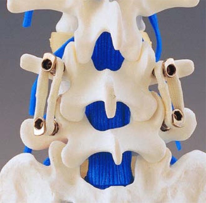
Introduced by Henri Graf, the Graf ligament was one of the first posterior dynamic devices used clinically (Figure 1). Under applied compressive force, the bands are preloaded to place the intervertebral segment in extension, allowing immobilization of the instrumented segment in lordosis.
Figure 1.
Graf ligament (SEM, Créteil, France) consists of 8 mm braided polyester non-elastic tension bands between pedicle screws (reprinted with permission).
Strauss et al. conducted a biomechanical in vitro cadaveric study to evaluate the impact of Graf ligament implantation on intervertebral motion.12 Thirteen cadaveric lumbar spines were tested (L2-3, n = 7 and L4-5, n = 6) by applying an axial compressive load of 500 N and pure bending moments of 10 Nm in flexion-extension, lateral bending, and axial rotation. Spinal specimens were tested in 3 different conditions: intact, destabilized (total laminectomy “pedicle to pedicle”), and re-stabilized by a Graf ligament. Balance point (defined as the loading point on the upper plate of the vertebra causing rotation less than 0.03°), compressive compliance, and ROM were determined for each testing condition.
As expected, the balance point of the injured segments was significantly displaced anteriorly whereas stabilized segments demonstrated a balance point more similar to intact spines. Instrumented spines also demonstrated significant reduction of ROM in flexion-extension and lateral bending compared to intact spines, and decreased overall flexibility for all the moments. Finally, the Graf ligament failed to reduce intervertebral motion in axial rotation (instrumented ROM was 107% to 132% of normal ROM) and translation of the vertebra in all 3 directions (Table 2).
Table 2.
Ranges of Motion of Intact, Injured, and Instrumented Spines From the Study of Strauss on Graf System (in Degrees)
| Level | INTACT | INJURED | INSTRUM with Graf Ligament | % (Inst/ Int) | |
|---|---|---|---|---|---|
| Flexion/ Extension | L2-L3 (n = 7) | 7.5 ± 3.2 | 9.7 ± 3.6 | 3.8 ± 2.6 | 48 |
| L4-L5 (n = 6) | 11.6 ± 2.9 | 14.3 ± 3.7 | 4.5 ± 2.2 | 39 | |
| Axial Rotation | L2-L3 (n = 7) | 4.1 ± 2.5 | 6.5 ± 3.3 | 5.4 ± 2.4 | 132 |
| L4-L5 (n = 6) | 5.4 ± 2.1 | 7.1 ± 2.7 | 5.8 ± 2.5 | 107 | |
| Lateral Bending | L2-L3 (n = 7) | 9.4 ± 2.8 | 10.6 ± 4.5 | 6.6 ± 4.3 | 70 |
| L4-L5 (n = 6) | 9.9 ± 3.3 | 10.2 ± 3.8 | 4.4 ± 2.6 | 45 | |
% = (ROMinstrum/ROMintact)×100
Dynesys
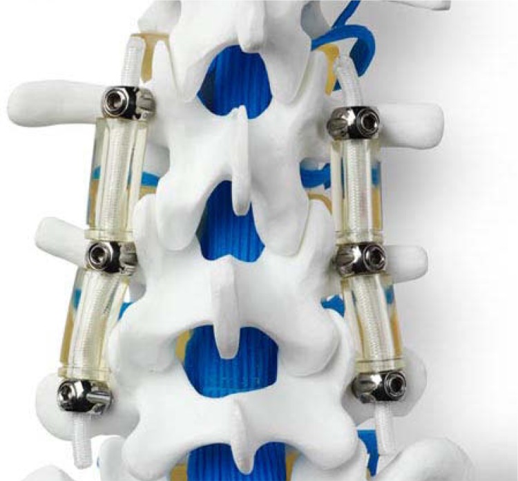
The Dynesys dynamic stabilization system (Figure 2) is designed to control flexion motion via tension on a polyethylene terephthalate (PET) cord, whereas in extension, motion is limited by the presence of a cylindrical plastic spacer.13 Results of experimental in vitro studies involving the Dynesys implant are presented in Table 3.
Figure 2.
Dynesys (DYnamic NEutralization SYStem, Zimmer Spine, Minneapolis, Minnesota) consists of a cylindrical polycarbonate urethane (PCU) spacer with a tensioned polyethylene terephthalate (PET) cord tunnelled through the PCU spacer (reprinted with permission from Zimmer Spine, Inc.).
Table 3.
Biomechanical Evaluation of Dynesys
| Study | INTACT | INJURED | INSTRUM with Dynesys | % (Inst/ Int) | |
|---|---|---|---|---|---|
| Flexion | Cheng et al. | - | - | - | - |
| Niosi et al. | 3.7 ± 1.5 | 6.1 ± 1.4 | 1 ± 0.6 | 27 | |
| Schmoelz et al. | 5 ± 2.4 | 7.6 ± 4.2 | 1 ± 2.3 | 20 | |
| Freudiger et al. | 9.6 ± 1.7 | - | 4.3 ± 0.9 | 45 | |
| Extension | Cheng et al. | - | - | - | - |
| Niosi et al. | 3.3 ± 1.5 | 4.4 ± 1.2 | 1.1 ± 0.7 | 33 | |
| Schmoelz et al. | 4 ± 2.4 | 7.3 ± 5.9 | 3.8 ± 4.2 | 94 | |
| Freudiger et al. | 2.1 ± 1 | - | 1.1 ± 0.9 | 52 | |
| Flexion/extension | Cheng et al. | 5.2 ± 2.7 | 6.6 ± 3.7 | 1.3 ± 0.4 | 25 |
| Niosi et al. | 7 | 10.5 | 2.1 | 30 | |
| Schmoelz et al. | 9 | 15 | 4.8 | 53 | |
| Freudiger et al. | 11.7 | - | 5.4 | 46 | |
| Axial rotation | Cheng et al. | 4.1 ± 1.8 | 5 ± 2.1 | 4.2 ± 1.9 | 102 |
| Niosi et al. | 4.2 ± 1.8 | 5.6 ± 2.4 | 3.2 ± 2 | 76 | |
| Schmoelz et al. | 2.1 | 4.9 | 3.8 | 181 | |
| Freudiger et al. | - | - | - | - | |
| Lateral bending | Cheng et al. | 4.9 ± 2.2 | 5.3 ± 2.6 | 2 ± 0.8 | 40 |
| Niosi et al. | 7.6 ± 2.8 | 10 ± 3.6 | 2 ± 1 | 26 | |
| Schmoelz et al. | 9 | 15 | 2.5 | 28 | |
| Freudiger et al. | - | - | - | - |
Cheng et al.,18 n = 6, L3-L4 tested, pure moment of ± 6 Nm, without preload
Niosi et al.,17 n = 10, L3-L4 tested, pure moment of ± 7.5 Nm, without preload
Schmoelz et al.,15 n = 6, L3-L4 tested, pure moment of ± 10 Nm, no axial preload
Freudiger et al.,14 n = 4, L4-L5 tested, 18.3 Nm flexion moment and 12.5 Nm extension moment
% = (ROMinstrum/ROMintact)×100
In 1999 Freudiger et al. reported the first in vitro evaluation of the Dynesys implant.14 Four cadaveric lumbar spines were tested utilizing sagittal plane bending moments of 18.3 Nm for flexion and 12.5 Nm for extension (Table 3).
The authors found that the implant significantly reduced segmental ROM in flexion/extension (by approximately a factor of 2) and horizontal translation; however, it tended to increase vertical translation (downward displacement in flexion and upward in extension). They attributed the increased vertical displacement to the posterior shift of the normal pivot point of the FSU.
Schmoelz et al. investigated the degree of stabilization conferred to the index interspace and the effect of Dynesys on the adjacent segment.15 Six lumbar cadaveric spines were loaded with pure moments of 10 Nm in 3 motion planes and evaluated in 4 different testing conditions: intact, injured (dissection of posterior ligaments, flava ligament, transection of facet joint capsules and posterolateral nucleotomy), stabilized with Dynesys at L3-4, and stabilized with rigid instrumentation at L3-4.
Compared to the intact spines, the Dynesys implanted specimen showed decreased flexion and lateral bending, equivalent extension, and more motion in axial rotation (Table 3). When comparing the dynamic and rigid instrumentation, Dynesys was comparable to rigid instrumentation in flexion but allowed more motion in extension, lateral bending and axial rotation. Interestingly, no significant difference in ROM and neutral zone (NZ) was noted at the adjacent level between intact and instrumented spines and between the two types of instrumentation in any of the three motion planes.
Three years later, Schmoelz et al. published an in vitro investigation comparing the load transfer to the intervertebral disk stabilized with either rigid instrumentation or Dynesys.16 Six lumbar specimens were tested under similar conditions to their previous study, and intradiscal pressure was measured by means of flexible pressure transducers. In the neutral unloaded position, no significant difference was observed in disk pressure under the four testing conditions. In extension, dynamic and rigid stabilization significantly reduced intradiscal pressure, whereas no significant difference was observed in flexion. In extension, negative pressures were recorded with the two types of stabilization methods suggesting complete unloading of the intervertebral disk. The authors hypothesized that pressure increase in flexion and pressure decrease in extension could be related to the posterior shift of the axis of rotation caused by the application of posterior instrumentation. Although reduction of intradiscal pressure was found in lateral bending, this was not significant. In axial rotation, pressure was significantly decreased following rigid fixation compared to the intact spines and slightly increased following implantation with the Dynesys device. The authors did not find any significant difference in intradiscal pressure at the adjacent level between rigid and dynamic stabilization or intact spines.
In 2006, Niosi et al. described a biomechanical study assessing the three-dimensional kinematic behavior of the Dynesys device with varying polymer spacer lengths to analyze the quality of motion with a special focus on the NZ and on the 3D helical axis of motion (HAM).17 Ten cadaveric specimens were tested by applying a pure moment of 7.5 Nm in five different testing conditions: intact, injured (section of posterior ligaments and facet joint capsules, posterolateral nucleotomy), stabilized with Dynesys (normal spacer, long spacer (+2 mm), and short spacer (-2 mm)). Implantation of the Dynesys device, compared to the intact and injured spines, resulted in significantly decreased ROM in all three loading directions (Table 3). In flexionextension and lateral bending, ROM decreased to 26% and 33% of the intact spine respectively, and axial rotation was approximately 76% of the intact spine. As expected, in vitro destabilization increased the NZ; however, implantation of the Dynesys restored the NZ to a magnitude less than that of the intact spine. In addition, the authors observed a significant posterior shift in the location of the HAM in flexion-extension and axial rotation after Dynesys implantation. Spacer length also affected intervertebral motion with the long spacers allowing the largest ROM in all loading conditions, whereas the short spacers resulted in a significant reduction of ROM compared to a standard spacer length. The authors hypothesized that the increased ROM associated with the long spacer may be related to the reduction of segmental compression with a less preloaded FSU as a consequence.
Cheng et al. conducted another biomechanical cadaveric study comparing the effect of rigid fixation versus dynamic posterior stabilization on ROM.18 In this study, 12 cadaveric lumbar spines were divided into 2 groups (Dynesys (n = 6) versus rigid fixation (n = 6)) and tested by applying a pure moment of 6 Nm in flexion-extension, lateral bending, and axial rotation. Each specimen was tested in 6 different testing conditions: intact, destabilized (partial discectomy (50%) and partial resection of facet joints (50%)), instrumentation at L3-4, instrumentation at L3-4 and L2-3, instrumentation at L3-4 with interbody cage at the same level, and finally instrumentation at L3- 4 and L2-3 with interbody cage at L3-4. Their results showed that following Dynesys at L3-4, ROM decreased to 25% of intact ROM in flexion-extension, 40% in lateral bending and increased to 102% in axial rotation (Table 3), whereas rigid instrumentation resulted in 32%, 39% and 78% of intact ROM, respectively. Interestingly, when the stabilization concerned only one level (L3- 4), no statistical difference was found between the two types of instrumentation in all three loading conditions at the instrumented and the adjacent level, L3-4 and L2-3 respectively. Dynesys behaved biomechanically similar to rigid instrumentation not only at the instrumented level but also at the adjacent level. When instrumentation involved 2 levels, Dynesys allowed significantly greater axial rotation at the instrumented levels. Finally, when used in conjunction with anterior column support and extended to the level above, the hybrid dynamic stabilization construct allowed more motion at the adjacent level, L2-3, compared with a similar length rigid pedicle screw based construct.
Niosi et al. performed another cadaveric study to measure facet loads before and after Dynesys stabilization using thin film electroresistive sensors.19 Surprisingly, the authors did not find facet joint unloading immediately after implantation, and in fact, an initial increase in facet loading was observed immediately after device implantation. Facet joint loading appears to be initially greater during flexion than that in extension, which is in contrast to the findings in the intact specimen. The authors attributed this finding to the pretensioning of the PET cord and possibly to the significant posterior shift in the location of the HAM in flexion-extension that occurs with implantation of the Dynesys device. In addition, the impact of spacer length may play a role with more pronounced facets loads and limited ROM associated with shorter spacers.
Meyers et al. compared the magnitude of moments within the pedicle screws between Dynesys and a total facet replacement system (TOPS) utilizing strain gauges in a cadaveric biomechanical study.20 Five cadaveric lumbar spines were tested in flexion-extension and lateral bending under axial compression loads of 210 and 630 N. ROM with Dynesys was initially stiffer than the TOPS device in both tested planes of motion. The moments recorded in the Dynesys were significantly higher than those of the TOPS system with increases of as much as 56% in flexion-extension and 86% in lateral bending. The authors concluded that the design of a posterior stabilization device influences the amount of load seen within the pedicle screws and indicated that reduction of such loads through even stress distribution between the spinal implant and bone may decrease the incidence of screw loosening. Limitations of this study are the absence of testing in axial rotation and the potential bias provided by the 2-3 mm distraction performed during Dynesys insertion.
Osteotech Dynamic Device
Xu et al.21 investigated this posterior dynamic implant manufactured by Osteotech in an in vitro cadaveric study. The aim of the study was to compare the stability provided by the Osteotech dynamic pedicle screw fixation device to an equivalent rigid device. Six thoracolumbar human spine specimens were tested by applying pure moments of 10 Nm in flexion-extension, lateral bending and axial rotation, under 4 different conditions: intact, injured (anterior wedge resection of vertebral body), stabilized with the dynamic device, stabilized with the rigid device. The authors found that the dynamic device was more flexible than the rigid device in flexion-extension and axial rotation whereas it was as stiff as in lateral bending. Interestingly, both dynamic and rigid systems restored the stability of the injured segment in flexion-extension, lateral bending and axial rotation. Compared to the intact spine, dynamic ROM was 72% of the intact spines in flexion-extension, 60% in lateral bending and 90% in axial rotation. The authors concluded that the Osteotech dynamic posterior implant may have the ability to optimally control the motion and load transmission of a FSU without sacrificing construct stability. To the best of our knowledge, this device has not undergone clinical testing.
Finite Element Modeling
Twinflex
Templier et al.22 evaluated the role of the longitudinal component in load transfer between the FSU and implant via finite element analysis (FEA) (Table 4). Using a 3D geometric FE L3-sacrum model, the authors compared load transmission of rigid instrumentation versus the semirigid Twinflex system (Figure 3) following the application of a flexion moment.
Table 4.
Summary of FEA Studies Involving Pedicle Screw- Based Dynamic Stabilization Devices (Currently Available and Used Clinically)
| References | Methods | Parameter(s) | Device |
|---|---|---|---|
| Templier et al., 199822 | 3D geometris FE L3-sacrum model Semirigid / rigid | Load transmission throughout the FSU and the instrumentation following application of a flexion moment | Twinflex |
| Zander et al., 200624 | 3D non linear FE Model of the lumbosacral spine Intact/Dynamic below rigid instrumentation | ROM, intradiscal pressure, facet joints forces and implant stresses In standing, 30° flexion, 20° extension, 10° axial rotation | Fictional device similar to Dynesys |
| Rohlmann et al., 200723 | 3D non linear FE Model of the lumbosacral spine Dynamic/Rigid | ROM, intradiscal pressure, facet joints forces and implant stresses In standing, 30° flexion, 20° extension, 10° axial rotation | Fictional device similar to Dynesys |
| Castellvi et al., 200525 | 3D non linear FE Model of the lumbosacral spine Semirigid/ Rigid | Adjacent level stresses Under flexion (45°), extension and axial loading | ISOBAR TTL |
FE Finite element
FSU Functional Spine Unit
ROM Range of motion
Figure 3.
Twinflex (SpineNetwork, Beaurains, France) consists of two 2.5 mm twin rods (reprinted with permission).
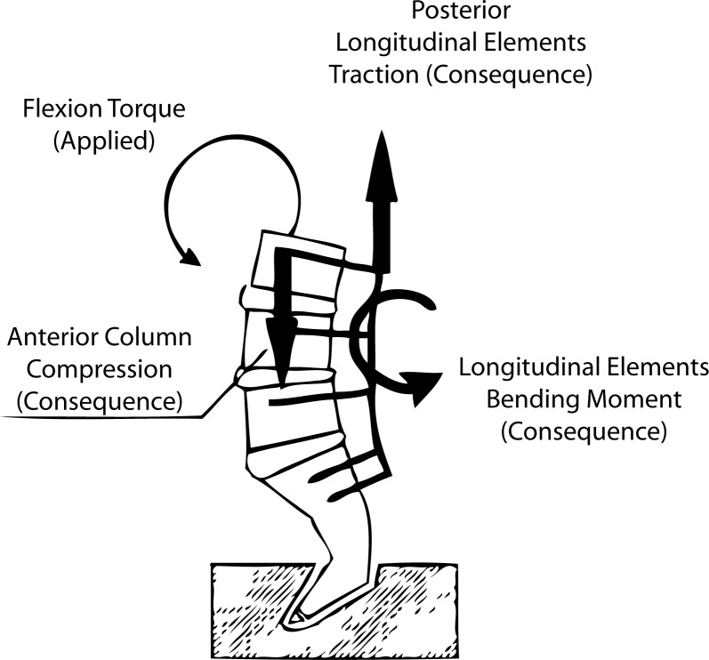
The authors noted that by reducing the flexural rigidity of lumbar fixation, there was more homogeneous load transmission throughout the FSU without significantly reducing the rigidity of the instrumented spinal segment. The application of rigid instrumentation was found to oppose the bending moment to an applied flexion moment whereas semirigid instrumentation balanced the applied flexion moment through load sharing via compression forces anteriorly and traction forces posteriorly (Figure 4). A rigid longitudinal element was found to concentrate stresses at the construct extremities while reducing loads within the intercalary segments. This may be theoretically responsible for the “stress-shielding” phenomenon observed following application of rigid instrumentation.
Figure 4.
In flexion, predominant load transfers through the system depends on instrumentation stiffness: A dynamic system results in anterior compression and posterior traction while a rigid system results in axial pull-out forces at the ends of the construct.22
Dynesys
Rohlmann et al.23 using finite element analysis, compared general load transmission through the FSU of a fictional bilateral dynamic stabilization device with traditional rigid instrumentation. The biomechanical properties of the fictional device were very similar to those of the Dynesys implant. Using a 3D nonlinear finite element model of the lumbo-sacral spine, the authors measured intervertebral ROM, intradiscal pressure, facet joints forces, and implant stresses. The model was loaded in four different conditions: standing, 30° flexion, 20° extension and 10° axial rotation. The effects of disk degeneration, posterior distraction and implant stiffness were also incorporated.
At the instrumented level, the dynamic implant reduced intervertebral ROM, decreased intradiscal pressure in extension and standing, and decreased overall facet joint forces as compared to intact spines. Following rigid instrumentation, the authors noted that these effects were more pronounced and there were fewer differences between dynamic and rigid stabilization than between the intact and the dynamically instrumented spines. The main consequence of disk degeneration on instrumented ROM was the reduction of intradiscal pressure in extension. Instrumentation distraction, simulated by a 2 mm extension of the longitudinal spacer length, strongly increased both axial and shear forces in the implant while decreasing overall intradiscal pressure.
Both dynamic and rigid stabilization were found to have a minimal effect on adjacent segment ROM and intradiscal pressure. Intervertebral motion was influenced by implant stiffness ranging between 1 to 1000 N/mm whereas implant stiffness greater than 1000 N/mm had a negligible effect.
Using a similar finite element model of the lumbo-sacral spine, Zander et al.24 analyzed the effect of a posterior dynamic implant inserted below a rigid construct combined with anterior interbody bone graft (ie rigid fixation and interbody graft at L2-3 and dynamic fixation at L3-4). As previously mentioned, the biomechanical properties of the fictional dynamic device were very similar to the of Dynesys implant. The model was loaded in four different conditions: standing, 50° flexion, 25° extension and 10° axial rotation.
As expected, the dynamic implant reduced intervertebral motion at L3-4 for all loading applications except axial rotation. Facet joint forces were also reduced after insertion of the dynamic implant, especially after distraction. Surprisingly, intradiscal pressure was not significantly affected by the dynamic implant. The authors’ findings did not confirm that dynamic devices significantly decrease stresses in the intervertebral disk and that biomechanical differences between dynamic and rigid instrumentation were actually smaller than assumed.
Isobar TTL
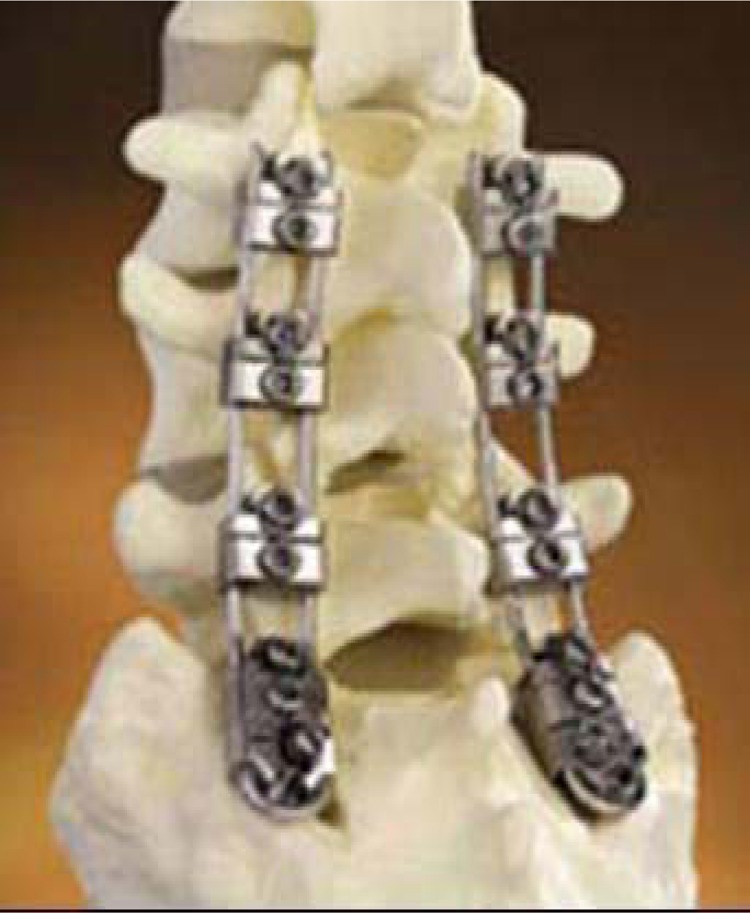
Castellvi et al.25 developed a 3D finite element model of the lumbar spine to evaluate adjacent level stresses following the application of a rigid versus dynamic Isobar TTL device (Figure 5).
Figure 5.
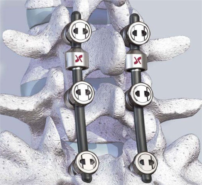
Isobar TTL (1997, evolution of Isolock device, Scient'x, Guyancourt, France) consists of 5.5 mm titanium alloy rod and a damper that reduces stiffness and allows a limited amount of angular and axial micromotion (reprinted with permission).
Preliminary biomechanical evaluation was performed by using a polyethylene model of the lumbar spine to determine the stiffness values of instrumented segments, which was then followed by FEA utilizing this data. In the FE model, the L5-S1 segment was fused and the L4-5 was stabilized with either rigid or dynamic (Isobar TTL) fixation. Spinal segments were then tested under flexion (45°), extension, and axial loading.
Compared to rigid instrumentation, dynamic stabilization resulted in the reduction of maximal stresses in the next adjacent level (L3-4) by approximately 5.5% in flexion but an increase of 17% at the instrumented disk level (L4-5). Reduced construct stiffness and increased axial motion noted within the dynamic lumbar instrumentation was thought to be responsible for the decreased adjacent level stress. In addition, areas of discal tissue exposed to high amplitude stresses were decreased by approximately a factor of 2 for disks adjacent to dynamic instrumentation, compared to those adjacent to rigid instrumentation. Interestingly, the authors found that increasing axial micromotion capacity of the dynamic device corresponded to further reduction of peak stresses more so than decreasing the rod stiffness. In addition, reducing rod stiffness and increasing axial motion together resulted in a more physiologic location of the instantaneous axis of rotation of the implanted segment.
DISCUSSION
The objective of this paper was to review the main biomechanical investigations reported on the currently available pedicle screw-based PDS devices. Biomechanical evaluation of spinal instrumentation can be performed utilizing three different types of evaluation: in vitro investigations, finite element analysis (FEA), and in vivo animal studies.26, 27 Animal studies are performed infrequently due to their high cost and technical requirements. In addition, because animals are quadrupeds, loads imposed on lumbar spinal devices may be not really appropriate in such animal models. In vitro and FEA investigations tend to be complementary and can provide comprehensive evaluation of biomechanical properties of implants in situ. Although FEA presents some theoretical advantages over in vitro experimental studies (ie, generally less time consuming and allowing measurement of a wider variety of variables and experimental conditions), cadaveric testing allows for in situ analysis of implants and verification of theoretical data. In addition, because of the complexity of most dynamic devices, finite element modeling generally represents only an approximate model of instrumentation behavior. In general FEA analysis uses displacement control (for example 45° flexion) whereas in vitro study uses load control (for example pure moments of 7.5 Nm). Displacement-control protocols postulate that patients move their spine to the same range of motion whatever they have an intact or a stabilized spine. Loadcontrol protocols suppose that patients limit motion of the lumbar spine during their physical activities. Finally, both FEA and in vitro studies have some limitations in that in vivo environment differs from experimental conditions and in vivo contributions of muscle groups are not evaluated.
For the purposes of our review, the main parameters measured in all of these biomechanical studies refer to kinematics of the FSU (ROM, NZ, location of helical axis of motion) and to load transmission (intradiscal pressure, facet forces, and stresses through the FSU and instrumentation). The helical axis of motion is used to depict the 3D movement of the cranial vertebra related to the caudal vertebra. During intervertebral motion, at each phase of the movement, the displacement of the cranial vertebra can be separated into a rotation about and a translation along a single axis, called helical axis of motion.
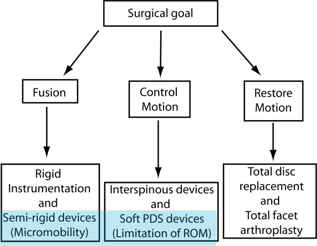
Pedicle screw-based PDS systems attempt to restore the normal biomechanics of the spinal column by restoring some physiologic motion and unloading the intervertebral disk and the posterior elements. However, the effects on motion following dynamic stabilization may vary significantly with implant design, and PDS devices have been subsequently categorized based on the magnitude of motion restriction. Although there is a lack of objective data to support such a classification, pedicle screw-based PDS systems are divided into semirigid rod systems used primarily for fusion and tension band-based posterior systems generally used as a nonfusion technology (Figure 6). Semirigid devices generally consist of metallic rods using hinges, springs, or bumpers to allow for partially controlled 3-dimensional motion or micromotion (ie, Twinflex, Isobar TTL). Tension-band, posterior-based systems (soft PDS) use a non-elastic band or a plastic rod to provide static tension between 2 pedicle screws (ie, Graf ligament, Dynesys). It should be noted that all pediclebased posterior dynamic stabilization devices currently approved for use by the FDA are intended to be used as adjuncts to fusion.
Figure 6.
“Soft” PDS systems have to be differentiated from “semirigid” dynamic instrumentation with which a fusion is generally intended.
To further analyze the biomechanical effects of pedicle screw-based PDS devices, we have to distinguish 2 different indications: fusion and nonfusion.
Fusion Conditions
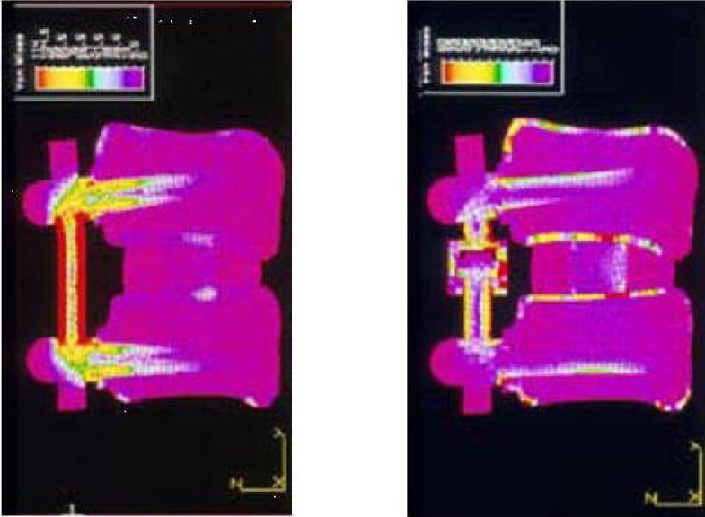
Pedicle screw-based PDS devices may serve to improve interbody fusion success.2, 28 It has been postulated that eliminating mechanical loads on an interbody graft may result in negative bone remodeling, pseudarthroses, and osteoporosis.29 This “stress shielding” phenomenon at the disk space level may be due to the supra-physiologic stiffness of traditional rigid instrumentation. Semirigid PDS devices theoretically are flexible enough to allow increased anterior column load-sharing (Figure 7) which may favor osteogenesis and enhance interbody fusion in accordance with Wolff's Law.30
Figure 7.
Finite element analysis comparing load distribution according to rigid (left) versus dynamic (right) instrumentation (with permission from F Lavaste and G Perrin, Laboratory of Biomechanics, ENSAM-PARISTECH, Paris, unpublished data, 1993).
Results from experimental work by Lavaste and Perrin (unpublished data) using finite element analysis demonstrated that dynamic posterior instrumentation compared to traditional rigid instrumentation increased the amount of load transmission through the anterior column (Figure 7). In 1993, by using a finite element model of the lumbar spine and comparing the effects of 3 different longitudinal devices (4.8 and 6.3 mm rods and plate), Duffield et al. demonstrated the impact of implant stiffness and longitudinal element size on load sharing.31 They found that 77% to 80% of the axial load was predicted to pass through the FSU when spinal segments were instrumented with either 6.3 mm rod or plates, compared to 90% when instrumented with 4.8 mm rods. Through a canine model, Lim et al. demonstrated that a less rigid stabilization device could reduce device-related osteopenia in the stabilized segments and around the spinal anchors or screws.32 Goel et al. developed a 3D finite element model to compare the load distribution of a hinged-dynamic posterior device versus a rigid construct. The authors found that the dynamic system enabled more load to be transferred through the anterior column and the interbody graft, as compared with rigid instrumentation, without compromising stability.33 These findings confirmed those reported by Templier et al.22 in 1998, suggesting that a dynamic device (Twinflex) could offer a more favorable environment for enhanced interbody fusion healing (Figure 4). Reducing the flexural rigidity of lumbar fixation results in more homogeneous load transmission along the system without reducing the rigidity of the whole system.
At the present time, pedicle screw-based PDS devices are FDA-approved as an adjunct for spinal fusion in combination with interbody fusion. Conversely, excessive flexibility may allow for excessive anterior loading of the interbody graft, resulting in endplate failure, subsidence, decrease fusion rates, and sagittal plane deformity (flatback).
Nonfusion Conditions
The 3 basic biomechanical requirements for an ideal dynamic stabilization device are: controlled physiologic motion (ROM and location of axis of rotation) without instability, even unloading of the intervertebral disk, and maintenance/restoration of sagittal balance.
Kinematics
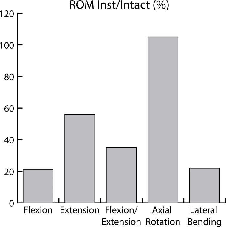
Throughout the literature, pedicle screw-based PDS devices have demonstrated a capacity to satisfactorily control motion and load transmission of a FSU without sacrificing construct stability. By reducing excessive intervertebral motion, implantation of such devices may result in relief of mechanical pain related to instability. However the stabilization after PDS was not evenly observed on 3-dimensional analysis. Biomechanical studies have demonstrated that pedicle screw-based PDS systems more efficiently control ROM in flexion-extension and lateral bending than in axial rotation. This is important clinically as these devices may not be beneficial in cases of rotational instabilities, lateral listhesis, or scoliosis deformities. As examples, ROM following implantation of the Dynesys device ranged from 20% to 45% of intact ROM in flexion, from 33% to 94% in extension, from 26% to 40% in lateral bending, and from 76% to 181% in axial rotation (Table 3).14, 15, 17, 18 Averaged ROM following implantation of the Dynesys device from 4 different in vitro studies are presented in Figure 8. Following implantation of the Graf ligament, ROM ranged from 39% to 48% in flexion/extension, from 45% to 70%, and from 107% to 132% in axial rotation (Table 2).
Figure 8.
ROM following implantation of the Dynesys implant compared to ROM of the intact spines (averaged results from 4 different human cadaveric in vitro studies).
To the best of the authors’ knowledge, no data has been published quantifying the effects on ROM following insertion of semirigid devices. Compared to soft PDS systems, these devices may result in greater control in motion, especially in axial rotation, which may justify their use in cases of deformity or instability. Although Freudiger et al.14 found that Dynesys implantation could partially control horizontal translation, semirigid devices appear more appropriate in cases of significant instability (such as degenerative spondylolisthesis).
The Dynesys device is the most investigated pedicle screw-based PDS system to date. Comparative baseline experimental human cadaveric analysis evaluating semirigid rod systems is unfortunately lacking. To date, no specific comparative studies between 2 different pedicle screwbased PDS systems have been reported in the literature. We assume that these devices are still in their infancy and that such essential studies will be forthcoming.
Both the design of the implant and the surgical technique have an impact on the biomechanical behavior of the instrumented spinal segment. As an example, the amount of intervertebral distraction or compression applied during implant insertion influences intervertebral ROM. The length of polymer spacer in a Dynesys construct significantly influences construct stiffness with a longer spacer resulting in a larger ROM in all loading conditions. The position of HAM is also affected by the length of the spacer whereas the initial stiffness of the construct appears to be dependent on how much the spacer is compressed during its application.
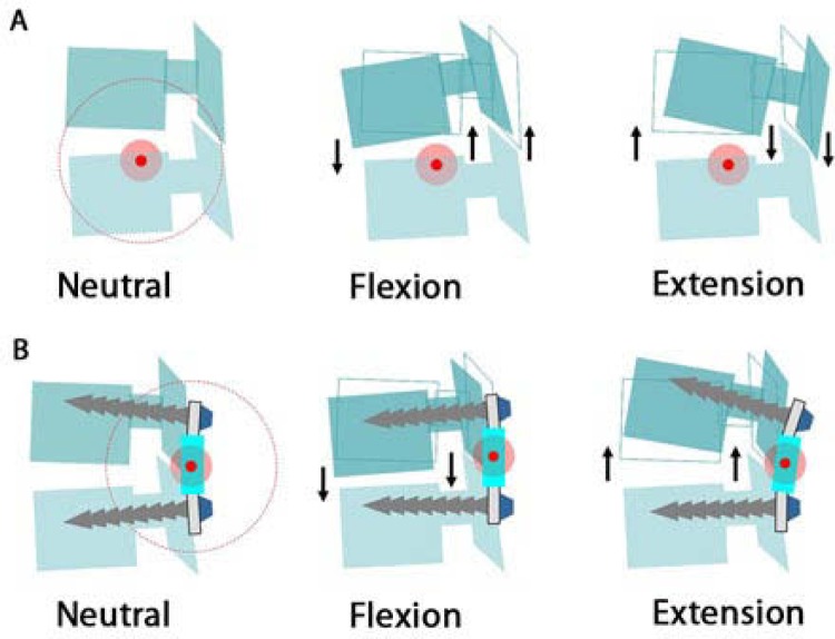
Reestablishment of normal segmental kinematics requires the restoration of physiologic range and quality of motion. The posterior shift of the HAM induced by most of the pedicle screw-based PDS results in a compression effect of the whole disk in flexion (anterior and posterior annulus) and a distraction effect, ie, the unloading of the whole disk, in extension (Figure 9B). This is in contrast to the normal kinematic behavior of the FSU (Figure 9A). Consequences on facet load are not well-investigated. In addition, the non-physiologic kinematics following pedicle screw-based device implantation may result in overloading of the intervertebral disk in some positions, especially when the spine is flexed (sitting position). Some authors propose the combined use of PDS devices with anterior total disk prosthesis to address concomitant disk and facet degeneration; however, this is controversial.
Figure 9.
Consequences of posterior shift of the helical axis of motion on intervertebral kinematics in flexion-extension.
Load Transmission
Although load transmission through the FSU following implantation of PDS systems was generally investigated by FEA, Schmoelz et al.16 measured intradiscal pressure in a human cadaveric study using flexible pressure transducers. This study confirmed the findings of FEA studies and showed significant unloading of the intervertebral disk in extension and after distraction, whereas flexion caused intradiscal loads comparable to the loads of the native spine (Table 5).
Table 5.
Load Transmission at the Instrumented Level Following Implantation of PDS Devices
| Loading Condition | Schmoelz et al.16 In Vitro Study | Zander et al. 24 FEA | Rohlmann et al.23 FEA | ||
|---|---|---|---|---|---|
| PDS | Rigid | PDS | PDS | Rigid | |
| Standing | NT | NT | NS | ↓ | ↓↓ |
| Flexion | NS | NS | NS | NS | NS |
| Extension | ↓↓ | ↓↓ | NS | ↓ | ↓↓ |
| Lat Bend | ↓ | ↓ | NT | NT | NT |
| Axial Rot | ↑ | ↓ | NS | NS | NS |
NT Not tested
NS Not significant
Asymmetrical load distribution within the intervertebral disk and the presence of high load zones has been recently postulated as one potential etiology for mechanical low back pain.11 An analogous process has been described for the pathogenesis of symptomatic arthritis resulting from hip and knee degeneration (the “stone in the shoe” theory by Mulholland8). This concept is supported by correlations between abnormal stress distribution across the disk space and painful disks on discography, and the fact that most lumbar spine radiographs fail to demonstrate macroscopic abnormal motion on dynamic views. In addition, position and posture have clear impact on pain in the chronic lowback pain population. Although current surgical treatment has focused on restricting intervertebral motion, abnormal transmission of load across the disk space is another potential significant source of low-back pain. Reduction of load transmission through the disk through implantation of PDS devices may result in relief of mechanical pain related to asymmetrical load distribution.
Sagittal Balance
Surprisingly few studies have focused on the relationship between spinopelvic alignment and pedicle screw-based PDS devices. Long-term effect of such devices on sagittal balance is not well-investigated. Through tensioning of the posterior annulus and ligamentum flavum, intervertebral distraction performed during PDS device insertion results in increased central canal and neuroforaminal dimensions, and therefore PDS devices have been proposed as an alternative option to treat spinal stenosis. However posterior distraction may induce focal kyphosis with a risk of sagittal imbalance. In addition, dynamic rods may pose difficulties when trying to restore lordosis and maintain spinal alignment in the setting of spinal deformity.34 Legaye et al. analyzed the spinal and pelvic parameters in a population of patients implanted with PDS systems and noted an increased rate of sagittal imbalance characterized by a loss of lumbar lordosis and a decrease in sacral slope.35 More long-term studies are needed to determine the impact of sagittal alignment alteration on clinical outcomes following dynamic stabilization.
Implant Longevity
If used as non-fusion constructs, dynamic devices must be able to bear load for the entire duration of implantation and stay anchored to the bone in the setting of continued intervertebral motion. Traditional rigid instrumentation used for fusion is typically load bearing until successful fusion is achieved; however instrumentation without fusion may be subject to fatigue failure and loosening at the screw-bone interface.
A recent clinical report by Stoll et al.36 reports rate of screw loosening at 10% in a series of 73 patients implanted with the Dynesys system after a mean follow-up of 38 months. Benezech and Mitulescu37 also reported the clinical and radiographical results of a series of 33 patients after semirigid stabilization with the ISOLOCK system without fusion. After a mean follow-up of 45-months, they noted the presence of 5/148 (3.3%) mechanical complications (3 cases of screw breakage, 1 case of cap screw loosening, and 1 case of instrumentation loosening). The authors, however, noted no correlation between the presence of mechanical complications and clinical results (functional outcomes were good or excellent in 76% of patients with 87% returning to previous work).
Adjacent Segment Disease
One of the ultimate objectives of dynamic technologies is to decrease the incidence of adjacent segment disease. Results from biomechanical studies15, 16, 23, 25, 38 suggest that the difference in the biomechanical effect between dynamic and rigid stabilization may not be as high as reported. For example, Schmoelz et al.16 reported no difference in intradiscal pressure at the adjacent segment for both dynamic and rigid stabilization compared to intact spines, and Castellvi et al.25 found only a 5.5% reduction in maximal stresses at the adjacent level provided by dynamic instrumentation versus rigid fixation. However, although the absolute disk stress reduction may be negligible, it may be clinically significant due to this effect being repeated over many loading cycles. Early clinical data39 suggest that results are as good as those reported using rigid instrumentation; however, long-term followup studies comparing dynamic versus rigid stabilization are needed to determine the efficacy of PDS on adjacent segment disease.
REFERENCES
- 1.Ghiselli G, Wang JC, Bhatia NN, Hsu WK, Dawson EG. Adjacent segment degeneration in the lumbar spine. J Bone Joint Surg Am. 2004;86:1497–1503. doi: 10.2106/00004623-200407000-00020. [DOI] [PubMed] [Google Scholar]
- 2.Huang RC, Girardi FP, Lim MR, Cammisa FP. Advantages and disadvantages of nonfusion technology in spine surgery. Orthop Clin North Am. 2005;36(3):263–269. doi: 10.1016/j.ocl.2005.02.006. [DOI] [PubMed] [Google Scholar]
- 3.Huang RC, Wright TM, Panjabi MM, Lipman JD. Biomechanics of non fusion implants. Orthop Clin North Am. 2005;36(3):271–280. doi: 10.1016/j.ocl.2005.02.010. [DOI] [PubMed] [Google Scholar]
- 4.Inceoglu S. Posterior dynamic stabilization of the lumbar spine. World Spine J. 2006;1:62–67. [Google Scholar]
- 5.Ishihara H, Osada R, Kanamori M, Kawaguchi Y, Ohmori K, Kimura T, Matsui H, Tsuji H. Minimum 10 year follow-up of anterior lumbar interbody fusion for isthmic spondylolisthesis. J Spinal Disord. 2001;14(2):91–99. doi: 10.1097/00002517-200104000-00001. [DOI] [PubMed] [Google Scholar]
- 6.Khoueir P, Kim A, Wang MY. Classification of posterior dynamic stabilization devices. Neurosurg Focus. 2007;22(1):E3. doi: 10.3171/foc.2007.22.1.3. [DOI] [PubMed] [Google Scholar]
- 7.Wright T, Tauber M, Meyers K, Sudin Y, Arnin U, Girardi F. The biomechanics of posterior motion preservation systems. Spine J. 2005;5:143S–144S. [Google Scholar]
- 8.Mulholland RC, Sengupta DK. Rationale, principles and experimental evaluation of soft stabilization. Eur Spine J. 2002;11:S198–S205. doi: 10.1007/s00586-002-0422-x. [DOI] [PMC free article] [PubMed] [Google Scholar]
- 9.McNally DS. Rationale for dynamic stabilization. In: Kim DH, editor. Dynamic Reconstruction of the Spine. New York, NY: Thieme Medical Publishers; 2006. pp. 237–243. [Google Scholar]
- 10.Nockels RP. Dynamic stabilization in the surgical management of painful lumbar spinal disorders. Spine. 2005;30:S68–S72. doi: 10.1097/01.brs.0000174531.19982.99. [DOI] [PubMed] [Google Scholar]
- 11.Sengupta DK. Dynamic stabilization devices in the treatment of low back pain. Orthop Clin North Am. 2004;35(1):43–56. doi: 10.1016/S0030-5898(03)00087-7. [DOI] [PubMed] [Google Scholar]
- 12.Strauss PJ, Novotny JE, Wilder DG, Pope MH. Multidirectional stability of the Graf system. Spine. 1994;19(8):965–972. doi: 10.1097/00007632-199404150-00016. [DOI] [PubMed] [Google Scholar]
- 13.Dubois GG, De Germay B, Prere J, Schwarzenbach O, Stoll TM. Dynamic neutralization: treatment of mobile vertebral instability. In: Kaech D, Jinkins J, editors. Spinal Restabilization Procedures. Philadelphia, Pennsylvania: Elsevier Health Sciences; 2002. pp. 345–354. [Google Scholar]
- 14.Freudiger S, Dubois G, Lorrain M. Dynamic neutralization of the lumbar spine confirmed on a new lumbar spine simulator in vitro. Arch Orthop Trauma Surg. 1999;119:127–132. doi: 10.1007/s004020050375. [DOI] [PubMed] [Google Scholar]
- 15.Schmoelz W, Huber JF, Nydegger T, Claes L, Wilke HJ. Dynamic stabilization of the lumbar spine and its effects on adjacent segments. An in vitro experiment. J Spinal Disord Tech. 2003;16:418–423. doi: 10.1097/00024720-200308000-00015. [DOI] [PubMed] [Google Scholar]
- 16.Schmoelz W, Huber JF, Nydegger T, Claes L, Wilke HJ. Influence of a dynamic stabilization system on load bearing of a bridged disc: an in vitro study of intradiscal pressure. Eur Spine J. 2006;15:1276–1285. doi: 10.1007/s00586-005-0032-5. [DOI] [PMC free article] [PubMed] [Google Scholar]
- 17.Niosi CA, Zhu Q, Wilson DC, Keynan O, Wilson DR, Oxland TR. Biomechanical characterization of the three-dimensional kinematic behaviour of the Dynesys dynamic stabilization system: an in vitro study. Eur Spine J. 2006;15:913–922. doi: 10.1007/s00586-005-0948-9. [DOI] [PMC free article] [PubMed] [Google Scholar]
- 18.Cheng BC, Gordon J, Cheng J, Welch WC. Immediate biomechanical effects of lumbar posterior dynamic stabilization above a circumferential fusion. Spine. 2007;32:2551–2557. doi: 10.1097/BRS.0b013e318158cdbe. [DOI] [PubMed] [Google Scholar]
- 19.Niosi CA, Wilson DC, Zhu Q, Keynan O, Wilson DR, Oxland TR. The effect of dynamic posterior stabilizasion on facet joint Contact Forces. Spine. 2008;33:19–26. doi: 10.1097/BRS.0b013e31815e7f76. [DOI] [PubMed] [Google Scholar]
- 20.Meyers K, Tauber M, Sudin Y, et al. The use of instrumented pedicle screws to evaluate load sharing in posterior dynamic stabilization systems. Spine J. 2008;8(6):926–932. doi: 10.1016/j.spinee.2007.08.008. [DOI] [PubMed] [Google Scholar]
- 21.Xu HZ, Wang XY, Chi YL, et al. Biomechanical evaluation of a dynamic pedicle screw fixation device. Clin Biomech. 2006;21:330–336. doi: 10.1016/j.clinbiomech.2005.12.004. [DOI] [PubMed] [Google Scholar]
- 22.Templier A, Denninger L, Mazel C, Lavaste F, Skalli W. Comparison between two different concepts of lumbar posterior osteosynthesis implants. A finite element analysis. Eur J Orthop Surg Traum. 1998;8:27–36. [Google Scholar]
- 23.Rohlmann A, Burra NK, Zander T, Bergmann G. Comparison of the effects of bilateral posterior dynamic and rigid fixation devices on the loads in the lumbar spine: a finite element analysis. Eur Spine J. 2007;16:1223–1231. doi: 10.1007/s00586-006-0292-8. [DOI] [PMC free article] [PubMed] [Google Scholar]
- 24.Zander T, Rohlmann A, Burra NK, Bergmann G. Effect of a posterior dynamic implant adjacent to a rigid spinal fixator. Clin Biomech. 2006;21:767–774. doi: 10.1016/j.clinbiomech.2006.04.001. [DOI] [PubMed] [Google Scholar]
- 25.Castellvi AE, Huang H, Vestgaarden T, Saigal S, Clabeaux DH, Pienkowski D. Finite element analysis of dynamic instrumentation demonstrates stress reduction in adjacent level discs. Paper presented at: World Spine III: The Third Interdisciplinary Congress on Spine Care, Rio de Janeiro, Brazil; July 31-August 3, 2005; Rio de Janeiro, Brazil. [Google Scholar]
- 26.Clausen JD, Goel VK, Sairyo K, Pfeiffer M. A protocol to evaluate semi-rigid pedicle screw systems. J Biomech Eng. 1997;119:364–366. doi: 10.1115/1.2796102. [DOI] [PubMed] [Google Scholar]
- 27.Goel VK, Gilbertson LG. Basic science of spinal instrumentation. Clin Orthop Relat Res. 1997;335:10–31. [PubMed] [Google Scholar]
- 28.Perrin G. Usefulness of intervertebral titanium cages for PLIF and posterior fixation with semi-rigid Isolock plates. In: Szpalski M, Gunsburg R, Spengler DM, Nachemson A, editors. Instrumented Fusion of the Degenerative Lumbar Spine: State of the Art, Questions and Controversies. Philadelphia, Pennsylvania: Lippincott-Raven Publishers; 1996. pp. 271–279. [Google Scholar]
- 29.Goel VK, Lim TH, Gwon J, et al. Effects of rigidity of an internal fixation device. A comprehensive biomechanical investigation. Spine. 1991;16:S155–161. doi: 10.1097/00007632-199103001-00023. [DOI] [PubMed] [Google Scholar]
- 30.Frost HM. A 2003 update of bone physiology and Wolff's Law for clinicians. Angle Orthodontist. 2004;74:3–15. doi: 10.1043/0003-3219(2004)074<0003:AUOBPA>2.0.CO;2. [DOI] [PubMed] [Google Scholar]
- 31.Duffield R, Carson W, Chen L, Voth B. Longitudinal element size effect on load sharing, internal loads, and fatigue life of tri-level spinal implant constructs. Spine. 1993;18:1695–1703. doi: 10.1097/00007632-199309000-00019. [DOI] [PubMed] [Google Scholar]
- 32.Lim TH, Goel VK, Winterbottom JM, et al. A comparison of stressinduced porosity due to conventional and a modified spinal fixation device. J Spinal Disord. 1994;7:1–11. doi: 10.1097/00002517-199407010-00001. [DOI] [PubMed] [Google Scholar]
- 33.Goel VK, Konz RJ, Chang HT, Grosland NM, Grobler LJ, Chesmel KD. Hinged-dynamic posterior device permits greater loads on the graft and similar stability as compared with its equivalent rigid device: a three-dimensional finite element assessment. J Prosthet Orthot. 2001;13:17–20. [Google Scholar]
- 34.Roussouly P, Gollogly S, Berthonnaud E, Dimnet J. Classification of the normal variation in the sagittal alignment of the human lumbar spine and pelvis in the standing position. Spine. 2005;30:346–353. doi: 10.1097/01.brs.0000152379.54463.65. [DOI] [PubMed] [Google Scholar]
- 35.Legaye J. Unfavorable influence of the dynamic neutralisation system on the sagittal balance. Rev Chir Orthop Reparatrice Appar Mot. 2005;91(6):542–550. doi: 10.1016/s0035-1040(05)84444-7. [DOI] [PubMed] [Google Scholar]
- 36.Stoll TM, Dubois G, Schwarzenbach O. The dynamic neutralization system for the spine: a multicenter study of a novel nonfusion system. Eur Spine J. 2002;11:S170–S178. doi: 10.1007/s00586-002-0438-2. [DOI] [PMC free article] [PubMed] [Google Scholar]
- 37.Benezech J, Mitulescu A. Retrospective patient outcome evaluation after semi-rigid stabilization without fusion for degenerative lumbar instability. Eur J Orthop Surg Traum. 2007;17:227–234. [Google Scholar]
- 38.Rohlmann A, Neller S, Bergmann G, Graichen F, Claes L, Wilke HJ. Effect of an internal fixator and a bone graft on intersegmental spinal motion and intradiscal pressure in the adjacent regions. Eur Spine J. 2001;10:301–308. doi: 10.1007/s005860100295. [DOI] [PMC free article] [PubMed] [Google Scholar]
- 39.Welch WC, Cheng BC, Awad TE, et al. Clinical outcomes of the Dynesis dynamic neutralization system: 1 year preliminary results. Neurosurg Focus. 2007;22(1):E8. doi: 10.3171/foc.2007.22.1.8. [DOI] [PubMed] [Google Scholar]


