

Abstract
Finite element (FE) models are advantageous in the study of intervertebral disc mechanics as the stress–strain distributions can be determined throughout the tissue and the applied loading and material properties can be controlled and modified. However, the complicated nature of the disc presents a challenge in developing an accurate and predictive disc model, which has led to limitations in FE geometry, material constitutive models and properties, and model validation. The objective of this study was to develop a new FE model of the intervertebral disc, to validate the model’s nonlinear and time-dependent responses without tuning or calibration, and to evaluate the effect of changes in nucleus pulposus (NP), cartilaginous endplate (CEP), and annulus fibrosus (AF) material properties on the disc mechanical response. The new FE disc model utilized an analytically-based geometry. The model was created from the mean shape of human L4/L5 discs, measured from high-resolution 3D MR images and averaged using signed distance functions. Structural hyperelastic constitutive models were used in conjunction with biphasic-swelling theory to obtain material properties from recent tissue tests in confined compression and uniaxial tension. The FE disc model predictions fit within the experimental range (mean ± 95% confidence interval) of the disc’s nonlinear response for compressive slow loading ramp, creep, and stress-relaxation simulations. Changes in NP and CEP properties affected the neutral-zone displacement but had little effect on the final stiffness during slow-ramp compression loading. These results highlight the need to validate FE models using the disc’s full nonlinear response in multiple loading scenarios.
Keywords: Intervertebral disc, Biphasic, Biphasic-swelling, Degeneration, Annulus fibrosus, Nucleus pulposus, Cartilaginous endplate
1. Introduction
Finite element (FE) models are advantageous in the study of intervertebral disc mechanics as the stress–strain distributions can be determined throughout the disc and the applied loading and material properties can be controlled and modified. Experimental studies are unable to isolate and quantify the role of individual tissues or specific factors correlated with aging and degeneration without invasive procedures such as nucleotomy (Johannessen et al., 2006), needle puncture (Martin et al., 2013), and enzymatic digestions (Boxberger et al., 2006; Jacobs et al., 2011), which induce structural and biochemical changes throughout the disc and obfuscate the interpretation of results. FE models have therefore been used to complement experimental studies and quantify critical elements intrinsic to both the healthy and degenerate disc that are otherwise unavailable or hard to control. FE studies have, for example, calculated the stresses experienced by annulus fibrosus (AF) fibers (Schroeder et al., 2006) and quantified the impact of disc geometry (Galbusera et al., 2011; Niemeyer et al., 2012; Noailly et al., 2007). Importantly, mechanical changes with disc degeneration have been identified, including increased range of motion and stress in compression, bending, axial rotation, and flexion/extension (Ruberte et al., 2009). FE studies have identified that failure initiates at the endplates in compressive and bending loads, and that AF tears are unlikely to occur in compression-only loading (Natarajan et al., 1994).
Intervertebral disc geometry is commonly represented in FE models using an idealized ‘kidney-bean’ profile (Little et al., 2007; Magnier et al., 2009; Motaghinasab et al., 2012; Schroeder et al., 2006; Stokes et al., 2011). Typically, the 3D shape is developed by taking multiple measurements, such as an average disc height, anterior–posterior distance, and lateral width, and extrapolating the remaining shape. This approach facilitates a geometry that is representative of a group of discs being tested because average measurements from all discs are used, however, it is often impractical to manually measure sufficient locations throughout the disc to capture its intricate 3D geometry and it is commonplace for these models to implement assumptions, such as constant disc height, to simplify the process. Yet, the importance of accurate geometry has been demonstrated; disc height and end-plate dimensions affect intradiscal pressure and range of motion (Niemeyer et al., 2012), while other changes in disc geometry alter the internal stress and strain distributions (Noailly et al., 2007). FE models seeking increased geometrical accuracy have therefore used sample-specific MR or CT imaging (del Palomar et al., 2008) to generate disc geometries with superior detail and spatial resolution. Although these are highly accurate, their geometry does not represent a group average; typically, single subject samples are chosen to represent the group.
Recently, the method of signed distance functions has been applied to quantify intervertebral disc shape (Peloquin et al., 2014). This technique uses high-resolution 3D MR images of multiple discs to create a mean geometry wherein every point in 3D space is an average of all the discs from the group of interest. The resulting shape is therefore fully determined and representative of the group-set that was imaged. This effectively combines the high-resolution advantage of image-based geometry with the abilities to represent the mean shape of a group-set, where idealized geometries have previously excelled. This technique has not previously been applied to FE models of intervertebral disc.
There is great diversity in the material models used in FE studies of the disc. The utilization of biphasic-swelling theory using anisotropic, nonlinear and inhomogeneous structural continuum models is becoming prevalent (del Palomar et al., 2008; Malandrino et al., 2009; Schroeder et al., 2010; Stokes et al., 2011). The material parameters used within these advanced constitutive theories are frequently selected from combinations of tissue-testing studies in the literature. However, the elastic and permeability properties of the CEP have only recently been determined through experimental tissue tests. Additionally, the published permeability properties for the NP and AF span several orders of magnitude, likely due to different initial conditions of the tissue and different testing protocols. Importantly, recent work has demonstrated that fitting material parameters to the standard biphasic model (without swelling) provides a different set of elastic and permeability parameters compared to the biphasic-swelling model (Cortes et al., 2014). Therefore, when constructing a biphasic-swelling disc model, it may be precarious to use the elastic and permeability parameters from the standard biphasic model and append an osmotic pressure contribution. In response to the aforementioned limitations, a new set of biphasic-swelling material parameters has recently been obtained (Cortes et al., 2014), wherein all of the disc soft tissues, including the CEP, were tested using a consistent protocol, and with initial conditions that would be similar to those of the FE disc model.
Validation is critical in order to confidently apply the findings of disc FE models. Validation is frequently performed only at the end-points of loading using global disc metrics such as total disc displacement, intradiscal pressure, and bulge. The reported values in experimental motion segment testing have large variability and are thus easily matched within a standard deviation. Especially problematic, this approach neglects the nonlinearity of disc stress–strain behavior and the time-dependent response, both essential to disc function. Calibration methods have been used to tune the material parameters of FE models, especially those of the AF fibers, in order for FE results to fit experimental data (Malandrino et al., 2013; Schmidt et al., 2006, 2007). Many studies that do include validation of the nonlinear stress–strain response use a similar procedure to calibrate or tune their material parameters (Noailly et al., 2011). Recently, the nonlinear response of a cervical disc was validated in flexion and extension without tuning or altering material parameters, but only for quasi-static loading (del Palomar et al., 2008).
The objective of this study was to develop a new FE model of the intervertebral disc utilizing an analytically based geometry, with material properties obtained from tissue-tests fit to biphasic-swelling theory, and to validate the model’s nonlinear and time-dependent responses without tuning or calibration. Additionally, this model was used to elucidate the contributions of the NP, CEP, and AF to the disc response in multiple axial compression experiments including quasi-static loading, creep, and stress relaxation.
2. Methods
2.1. Finite element mesh
In order to obtain the disc geometry for the FE simulations, 7 human L4/L5 intervertebral discs with a degeneration score of 3 were imaged using a high-resolution (200μm isotropic) 3D MR sequence. The volumetric shape of each disc was averaged using signed distance functions following the methods outlined in Peloquin et al. (2012) and Tsai et al. (2003), resulting in an analytically-based 3D geometry that represented the mean shape of the group of discs imaged (Fig. 1).
Fig. 1.
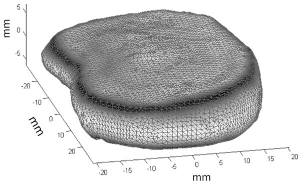
Mean shape (not-meshed) of L4/L5 human disc based on principal component analysis of high resolution MRI (200 μm isotropic) of seven human discs.
The mean disc shape was processed using a custom Matlab (MathWorks, MA) routine to generate the FE mesh (Fig. 2A). An intermediate 2D quad mesh of the disc’s axial silhouette was created, formed using a combination of concentric contours of quad elements and a central rectangular grid (Fig. 2B). This arrangement of concentric contours allowed the AF elements to be aligned with the disc’s circumferential axis, such that each element’s local coordinate frame could be used to define the local collagen fiber direction, which was oriented at ±25° to the disc circumferential axis (Guerin and Elliott, 2006). The NP encompassed 31% of the disc axial area and the center of the NP was positioned with a posterior offset equal to 10% of disc anterior–posterior length (O’Connell et al., 2007).
Fig. 2.
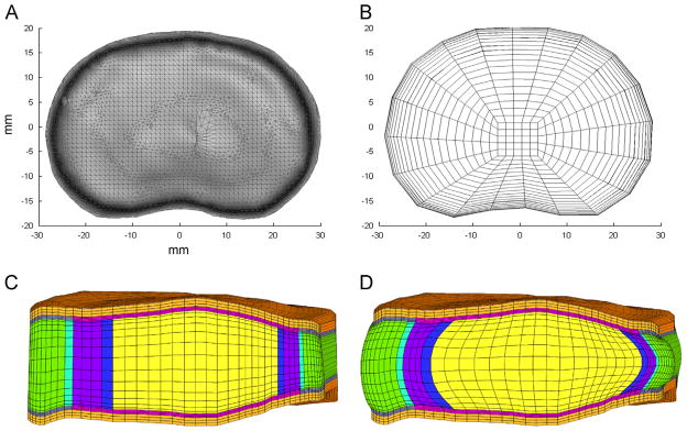
(A) Axial view of mean disc geometry. (B) 2D mesh created using axial silhouette of mean disc geometry. (C) Mid-sagittal plane-cut of complete vertebra–disc–vertebra segment after 3D extrusion and meshing. (D) Final mesh after simulated hydration in saline solution for 24 h. Swelling has induced characteristic bulge of nucleus pulposus and annulus fibrosus. Colors: orange: vertebral bone, gray: bony endplate, pink: cartilaginous endplate, green: outer annulus fibrosus, purple: inner annulus fibrosus, yellow: nucleus pulposus, blue: transition region between nucleus and inner annulus and aqua: transition region between outer and inner annulus fibrosus.
The 3D mesh (Fig. 2C) was composed of 8-node hexahedral elements (10,625 elements, 11,336 nodes), created initially by stacking copies of the 2D quad mesh in vertical layers along the axis of the disc height and subsequently projecting the surface nodes to the boundary of the average human disc geometry. The cartilage and bony endplates were then created by extruding the superior and inferior element layers of the disc by 500 μm, which was chosen based on recent histological and MR measurements of CEP (Moon et al., 2013). A similar process was used to create vertebral bodies, with a height of 0.5 mm and 3-element layers. In order to establish the final geometry, hydration for 24 h in PBS was simulated. During this time the vertebral bodies were constrained, causing the disc to pressurize and bulge outwards, achieving its final geometry (Fig. 2D).
2.2. Constitutive models
Structurally based hyperelastic continuum models were used, which are advantageous as they link the mechanical response of tissues to their constituent components including the nonfibrillar solid matrix, collagenous fibers, hydration, and fixed charge density. In order to capture both the equilibrium and transient mechanics, biphasic-swelling theory was implemented (Garcia and Cortes, 2007; Lai et al., 1997; Laible et al., 1993; Mow et al., 1980, 1989), wherein each tissue is considered a mixture of a porous solid saturated by a fluid phase. The total Cauchy stress, σ, is then the summation of its solid elastic stress, σe, fluid pressure, pf, and osmotic pressure, pos,
| (1) |
where I is the identity tensor. The constitutive formulations for the solid elastic stress (σe) utilize the integrity basis of invariants (Ii, i = 1–5) of the right Cauchy–Green deformation tensor C as
| (2) |
where F is the deformation gradient, and a and b are unit vectors representing collagen fiber orientations in the reference configuration.
The nonfibrillar matrix of the disc soft tissues, including the AF, NP and CEP, were modeled with a compressible Holmes–Mow formulation, previously used for of cartilage and AF matrix (Cortes and Elliott, 2012; Garcia and Cortes, 2006). This formulation is a function of invariants I1−I3 and material parameters c1 (MPa), c2 (unitless) and c3 (unitless), as
| (3) |
where β = c1 + 2c2 and is a nonlinear stiffening coefficient. Material properties c1−c3 are related to Young’s modulus (E) and Poisson’s ratio (ν) using the following transformation equations (Garcia and Cortes, 2006):
| (4) |
Alternate expressions of the Holmes–Mow model express the strain-energy as a function of Lamé parameters, which are in turn related to Young’s modulus and Poisson’s ratio (Ateshian et al., 1997; Holmes and Mow, 1990; Iatridis et al., 1998; Maas et al., 2014).
Material parameters c1−c3 for each tissue were obtained by fitting experimental confined compression force–displacement data (Cortes et al., 2014) and are listed in Table 1.
Table 1.
Material properties used for each of the disc soft tissues. NP: nucleus pulposus, CEP: cartilaginous endplate, OAF: outer annulus fibrosus, IAF: inner annulus fibrosus, E: modulus, ν: Poisson’s ratio, β: nonlinear parameter of the Holmes–Mow model, c4: AF fiber stiffness, c5: AF fiber nonlinear parameter, k0: hydraulic permeability at reference configuration, M: nonlinear parameter of the permeability, FCD: fixed charge density. Parameter values taken from Cortes et al. (2014).
| Material property | NP | CEP | OAF | IAF |
|---|---|---|---|---|
| E (kPa) | 64.9 | 305 | 18 | 26 |
| ν (unitless) | 0.24 | 0.18 | 0.24 | 0.16 |
| β (unitless) | 0.95 | 0.29 | 3.4 | 2.1 |
| c4 (kPa) | N/A | N/A | 296 | 796 |
| c5 (unitless) | N/A | N/A | 65 | 2 |
| k0 × 10−16 (m4/Ns) | 5.5 | 5.6 | 47 | 25 |
| M (unitless) | 1.92 | 3.79 | 5.75 | 3.5 |
| FCD (mM) | 379 | 248 | 44 | 55 |
| Initial porosity | 0.79 | 0.6 | 0.77 | 0.77 |
In addition to the nonfibrillar matrix, the AF included two fiber populations. Each fiber population was represented using an exponential stress–stretch relationship that is a function of material properties c4 (MPa) and c5 (unitless) that represent fiber stiffness and nonlinearity and invariant I4 or I5, defined in Eq. (2), which is the fiber stretch squared. The complete formulation for the AF was therefore the summation of the matrix and both fiber terms,
| (5) |
The fibers were constrained such that they only contributed to the AF strain-energy when they were in tension and fiber properties were calculated from fits to uniaxial tensile stress–strain data (Jacobs et al., 2013) and are listed in Table 1.
Vertebral bodies were modeled using a compressible neo-Hookean material
| (6) |
where μ and λ are Lamé parameters and J is the determinate of the deformation gradient F. The Lamé parameters are related to Young’s modulus and Poisson’s ratio through the transformation equation:
| (7) |
Material parameters E (12,000 MPa) and ν (0.3) were selected from the literature (Williams et al., 2007). The relative stiffness of the vertebral bodies compared to the intervertebral disc causes the vertebral bodies to act similarly to a rigid body, however, in order to permit fluid flow through the vertebral bodies they were modeled as a biphasic material with high modulus.
A nonlinear, strain-dependent Holmes–Mow permeability model was used for outer and inner AF, NP, and CEP, defining permeability, k, as
| (8) |
where φ0 is the solid volume fraction, k0 is permeability in reference configuration, and M is an exponential strain-dependence coefficient. Material parameters k0 and M were determined through fits to confined compression experiments and are listed in Table 1 (Cortes et al., 2014). Vertebral bodies, which undergo very small deformations in the simulations performed in this study, were prescribed a constant permeability of 5 mm4/N s (Ferguson et al., 2004).
The NP, CEP, and AF contain a significant amount of charged proteoglycan, leading to tissue-specific fixed charge density (FCD). In order to maintain charge neutrality with surrounding fluid, counter-ions flow into or out of the tissues, creating an osmotic pressure, pos, which was modeled with a Donnan equilibrium term
| (9) |
where R is the universal gas constant, T is the absolute temperature, cfc is the FCD and cb is the osmolarity of the surrounding fluid. Strain induced changes in fixed charge density are calculated using the relationship:
| (10) |
where cfc0 and φ0 are the fixed charge density and the water content at the reference configuration. Parameters used for the disc model are listed in Table 1.
2.3. Loading protocol and boundary conditions
As described in the FE mesh section, prior to loading, a hydration simulation was performed wherein the disc model was introduced to an external saline bath and allowed to equilibrate 24 h while the vertebral bodies were constrained. This follows experimental procedure and allows the FE disc model to pressurize, with the osmotic loading causing the disc to swell outward, inducing the characteristic bulge of the outer AF.
The FE model was then used to simulate the quasi-static and time-dependent response of the intervertebral disc in axial compression (Fig. 3), following established protocols (O’Connell et al., 2011; Peloquin et al., 2014). All simulations were performed in FEBio (Maas et al., 2012). The disc quasi-static response was quantified during a 2000 N slow-loading ramp at 1 N/s while displacement of the superior vertebral body was measured (Fig. 3A). The time-dependent response was quantified through two loading protocols: creep and stress-relaxation. For the creep protocol, a 1000 N load was applied in 1.5 s and held for 4 h (Fig. 3B). Time–displacement data were measured. For stress-relaxation, a 5% compression was applied in 10 s and held for 1 h, while the time–force data were recorded (Fig. 3C).
Fig. 3.
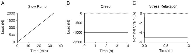
Protocol for the three loading modalities simulated: (A) slow ramp: a quasi-static ramp to 2000 N applied at 1 N/s, (B) creep: 1000 N applied in 1.5 s and held for 4 h creep, (C) stress relaxation: 5% nominal strain applied in 10 s and held for 1 h.
During each protocol the nodes on the inferior surface of the inferior vertebra were constrained in all directions. Loads were applied to a rigid body affixed to the nodes along the superior surface of the disc superior vertebra. The rigid body was constrained such that no rotations or displacements were allowed other than in the loading axis. A zero-fluid pressure boundary condition was applied to the peripheral surfaces of the disc, allowing free fluid flow into and out of the disc in response to osmotic and applied loads.
2.4. Validation
For purposes of model validation, the FE disc response was plotted against an experimental window consisting of the mean±95% confidence interval (CI) of the experimental results (O’Connell et al., 2011; Yoder et al., in preparation). The experimental data used for the validation consisted only of discs with grade 3 degeneration in order to provide consistency between the degeneration grades in the discs used for geometry, those used for tissue testing for material parameters, and those used in experimental motion segment testing. Importantly, no tuning or adjustment of material parameters was used to improve the FE fit.
2.5. Role of NP, CEP, and AF
The role of the NP, CEP, and AF tissue properties was investigated to determine the impact of each tissue on viscoelastic disc mechanics in compression. A set of high and low parameters were selected for each tissue from individual tissue tests, and are listed in Table 2. For the NP and CEP, data from Cortes et al. (2014) were used. For each tissue, two individual tissue responses were selected to represent the high- and low-load response of all the tissues tested. This selection was based on proximity to the mean±standard deviation of the experimental group response. Using experimental data from a single sample ensured a physically permissible combination of tissue properties for the nonlinear constitutive models. The elastic, permeability, and swelling properties from these tissues were then used to replace the FE model’s NP and subsequently CEP parameters and the slow ramp, creep and stress-relaxation simulations were repeated. For the AF, a similar procedure was used to find a set of high- and low-fiber properties from the data in Jacobs et al. (2013). In order to isolate the role of the individual tissues, the remaining disc properties were not altered (Table 1).
Table 2.
Material properties used to replace the mean NP, CEP, or AF property from Table 1 to evaluate the effect of altered NP or CEP property on the disc response to axial loading.
| Material property | NP
|
CEP
|
AF
|
|||
|---|---|---|---|---|---|---|
| High | Low | High | Low | High | Low | |
| E (kPa) | 96 | 27 | 784 | 227 | 33 | 10 |
| ν (unitless) | 0.42 | 0 | 0.34 | 0 | 0 | 0.11 |
| β (unitless) | 3.9 | 0 | 0 | 0.7 | 1.3 | 2.0 |
| c4 (kPa) | N/A | N/A | N/A | N/A | 795 | 44 |
| c5 (unitless) | N/A | N/A | N/A | N/A | 27 | 200 |
| k0 ×10−16 (m4/N s) | 7 | 3 | 4 | 6 | 42 | 48 |
| M (unitless) | 1.4 | 3.1 | 8.0 | 1.7 | 0.26 | 0.23 |
| FCD (mM) | 379 | 141 | 255 | 312 | 75 | 41 |
| Initial porosity | 0.81 | 0.77 | 0.67 | 0.7 | 0.74 | 0.77 |
3. Results
3.1. Validation
Color maps of Lagrange strain and Cauchy stress confirmed expected distribution patterns (Fig. 4). After hydration (Fig. 5A), fluid has entered the disc and caused the outer AF to bulge radially outward. The hydration also caused central parts of the disc to experience compressive forces as the constraints on the vertebral bodies countered the tendency for the swelling to increase disc height. After loading (Fig. 5B), the greatest compression was in the NP while tension was observed in the AF.
Fig. 4.
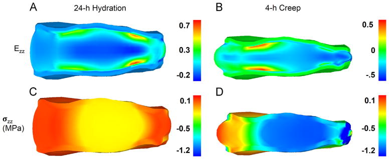
Axial Lagrange strain (Ezz: A,B) and Cauchy stress (σzz: C,D, MPa) after 24 h hydration (A,C) and at the end of 4 h creep at 1000 N (B,D).
Fig. 5.
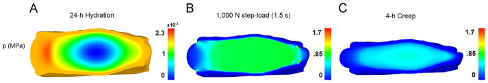
Fluid pressure (MPa) at the end of the 24 h hydration (A), immediately following the application of the 1000 N step-load (B), and after 4 h of creep (C).
The FE predictions for slow ramp, creep, and stress-relaxation simulations fit well within the experimental window (Fig. 6A–C). Importantly, validation included the entire nonlinear response for quasi-static and time-dependent axial compression and no material parameter tuning was performed.
Fig. 6.

Validation of finite element model showing experimental 95% confidence interval (shaded blue) and FE model simulation (red line) in slow ramp, creep and stress Relaxation. The effect on load–displacement response for alterations in NP (A–C), CEP (D–F) and AF (G–I) material properties are shown with the green “+” symbol representing the response with the higher material properties and the black “−” symbol representing the response with the lower properties.
3.2. Role of NP, CEP, and AF
Altering the NP, CEP, and AF properties caused the FE disc response to deviate from its original behavior (Fig. 6).
3.2.1. NP
The set of high NP material properties had minimal impact on the disc response for slow ramp, creep, or stress relaxation. The low NP properties decreased the initial toe-region, or neutral-zone, stiffness of the slow ramp, while final stiffness was unchanged. For creep, the low NP properties resulted in increased initial and total creep displacement and for stress-relaxation, the low NP properties resulted in reduced peak and equilibrium loads (Fig. 6A–C).
3.2.2. CEP
For the slow ramp, the set of high CEP material parameters had minimal impact on the disc response in slow ramp, creep, or stress-relaxation. The set of low CEP parameters increased the slow ramp neutral-zone displacement. Similar to the NP, the low CEP parameters increased initial and total creep displacement. In contrast to the NP, the set of low CEP material properties did not significantly alter the disc stress-relaxation response (Fig. 6D–F).
3.2.3. AF
For the slow ramp, changes in AF altered the load response after the neutral-zone (1 mm displacement), with the high parameters increasing and the low parameters decreasing the load response. In stress-relaxation, the high parameters caused a significant increase in the instantaneous load response of the disc, while not affecting the equilibrium response (Fig. 6G–I).
4. Discussion
In this study, a new FE model of the intervertebral disc was developed, validated, and applied to study the effect of altered NP, CEP, and AF material properties. Primary advantages of this disc model include the innovative approach in obtaining a quantitative mean disc geometry from a human dataset, biphasic-swelling tissue parameters obtained at the tissue-testing level, and validation of the entire nonlinear response in axial compression at multiple loading rates, with no tuning or adjustment of parameters.
The disc model was validated by comparison to the full nonlinear response of disc motion segment experiments in axial compression for 3 critical loading modalities: quasi-static slow ramp, constant-load creep, and stress-relaxation (Fig. 3). In all cases, the FE model response was within the experimental 95% confidence interval (Fig. 6). Critically, the tissue-level material properties did not need adjustment or calibration in order to allow the FE disc response to fall within the experimental range. This can be considered a predictive validation, as the loading modalities that were used at the full-disc level were different from those used to obtain tissue material parameters. This validation is more complete than many disc FE studies, which often compare only one loading modality and typically use only the endpoints of loading for validation metrics, as opposed to the complete nonlinear response (Renner et al., 2007).
The importance of utilizing the entire nonlinear response of multiple loading modalities is exemplified by observing the disc response with a range of NP, CEP, and AF values (Fig. 6). Changes in NP and CEP had little impact on the final stiffness of the slow-ramp, however, they affected the neutral-zone response in axial compression. If model validation were only to consider the final stiffness during slow-loading, a FE model with inaccurate NP and CEP values may still match experimental values.
In addition to highlighting the importance of model validation techniques, altering the NP and CEP properties elucidated key mechanical functions of each tissue on the disc behavior. Lowering the NP or CEP properties reduced the neutral-zone stiffness and caused an increase in neutral-zone displacement during the slow ramp, with no observable effect on final stiffness. These findings are consistent with experimental studies (Johannessen et al., 2006; Shea et al., 1994) and indicate that for slow-rate axial compression, the NP and CEP function primarily in the neutral-zone, controlling the initial stiffness and displacement, and have only a minor role in the linear-region, where changes in the AF were shown to affect the disc response (Fig. 6G).
The function of the NP and CEP is different in creep and stress-relaxation than it is in slow-rate loading. Lowered NP or CEP properties increased creep displacement throughout the duration of loading. Experimentally, trans-endplate nucleotomy in the ovine disc increased neutral-zone displacement and total range of motion as well as initial creep displacement, creep rate, and total creep (Johannessen et al., 2006). In stress-relaxation, lower NP properties resulted in reduced initial and final load response, while higher NP properties and both higher and lower CEP properties had no significant effect on the load response. Stress-relaxation is thought to occur as a result of fluid-flow out of the disc. While a primary flow pathway is expected to be axially through the CEP, it is possible that changes in CEP properties may be compensated by increased radial flow through the AF, resulting in insignificant changes in global disc load response over time. Further study is needed to quantify the stress–strain and fluid pressure distributions throughout the disc.
Although this study presents a strong validation and novel geometry, there are limitations. Torsion and bending are important to the physiological disc loading, however, they were not included in this study. Future experimental disc testing are needed to yield the dataset necessary to validate the FE model in these additional loading modalities. Further, although this study measured the impact of NP and CEP material properties on the disc mechanics, it was limited to the overall segment response and only a single high and low variation in material properties. Future studies will include a wider range of material property changes that are linked to disc degeneration and will quantify the effect on the internal stress–strain and fluid flow throughout the disc.
In conclusion, a new FE model of the intervertebral disc was developed utilizing the mean geometry of a population of human L4/L5 discs. Structural hyperelastic constitutive models were used in conjunction with biphasic-swelling theory to ensure the model was capable of capturing the impacts of structural changes on the disc mechanical response. The model was validated in axial compression using the entire nonlinear response and at multiple loading rates. Finally, the model was used to assess the role of the NP and CEP on intervertebral disc mechanics. Comprehensively validated disc models will provide quantitative insight into the internal mechanics and stress–strain distributions of the intervertebral disc, and also provide a means for predicting the impact of potential therapeutics on restoring native function.
Acknowledgments
This study was funded by the National Institute of Arthritis and Musculoskeletal and Skin Diseases (R01AR050052). We acknowledge the developers of the open source software FEBio (www.febio.org).
Footnotes
Conflict of interest
The authors do not have any conflict of interests to disclose.
References
- Ateshian GA, Warden WH, Kim JJ, Grelsamer RP, Mow VC. Finite deformation biphasic material properties of bovine articular cartilage from confined compression experiments. J Biomech. 1997;30:1157–1164. doi: 10.1016/s0021-9290(97)85606-0. [DOI] [PubMed] [Google Scholar]
- Boxberger JI, Sen S, Yerramalli CS, Elliott DM. Nucleus pulposus glycosaminoglycan content is correlated with axial mechanics in rat lumbar motion segments. J Orthop Res. 2006;24:1906–1915. doi: 10.1002/jor.20221. [DOI] [PubMed] [Google Scholar]
- Cortes DH, Elliott DM. Extra-fibrillar matrix mechanics of annulus fibrosus in tension and compression. Biomech Model Mechanobiol. 2012;11:781–790. doi: 10.1007/s10237-011-0351-x. [DOI] [PMC free article] [PubMed] [Google Scholar]
- Cortes DH, Jacobs NT, DeLucca JF, Elliott DM. Elastic, permeability and swelling properties of human intervertebral disc tissues: A benchmark for tissue engineering. J Biomech. 2014;47:2088–2094. doi: 10.1016/j.jbiomech.2013.12.021. http://dx.doi.org/10.1016/j.jbiomech.2013.12.021. Epub 2013 Dec 25. [DOI] [PMC free article] [PubMed] [Google Scholar]
- del Palomar AP, Calvo B, Doblare M. An accurate finite element model of the cervical spine under quasi-static loading. J Biomech. 2008;41:523–531. doi: 10.1016/j.jbiomech.2007.10.012. [DOI] [PubMed] [Google Scholar]
- Ferguson SJ, Ito K, Nolte LP. Fluid flow and convective transport of solutes within the intervertebral disc. J Biomech. 2004;37:213–221. doi: 10.1016/s0021-9290(03)00250-1. [DOI] [PubMed] [Google Scholar]
- Galbusera F, Schmidt H, Neidlinger-Wilke C, Wilke HJ. The effect of degenerative morphological changes of the intervertebral disc on the lumbar spine biomechanics: a poroelastic finite element investigation. Comput Methods Biomech Biomed Eng. 2011;14:729–739. doi: 10.1080/10255842.2010.493522. [DOI] [PubMed] [Google Scholar]
- Garcia JJ, Cortes DH. A nonlinear biphasic viscohyperelastic model for articular cartilage. J Biomech. 2006;39:2991–2998. doi: 10.1016/j.jbiomech.2005.10.017. [DOI] [PubMed] [Google Scholar]
- Garcia JJ, Cortes DH. A biphasic viscohyperelastic fibril-reinforced model for articular cartilage: formulation and comparison with experimental data. J Biomech. 2007;40:1737–1744. doi: 10.1016/j.jbiomech.2006.08.001. [DOI] [PubMed] [Google Scholar]
- Guerin HA, Elliott DM. Degeneration affects the fiber reorientation of human annulus fibrosus under tensile load. J Biomech. 2006;39:1410–1418. doi: 10.1016/j.jbiomech.2005.04.007. [DOI] [PubMed] [Google Scholar]
- Holmes MH, Mow VC. The nonlinear characteristics of soft gels and hydrated connective tissues in ultrafiltration. J Biomech. 1990;23:1145–1156. doi: 10.1016/0021-9290(90)90007-p. [DOI] [PubMed] [Google Scholar]
- Iatridis JC, Setton LA, Foster RJ, Rawlins BA, Weidenbaum M, Mow VC. Degeneration affects the anisotropic and nonlinear behaviors of human anulus fibrosus in compression. J Biomech. 1998;31:535–544. doi: 10.1016/s0021-9290(98)00046-3. [DOI] [PubMed] [Google Scholar]
- Jacobs NT, Cortes DH, Vresilovic EJ, Elliott DM. Biaxial tension of fibrous tissue: using finite element methods to address experimental challenges arising from boundary conditions and anisotropy. J Biomech Eng. 2013;135:021004. doi: 10.1115/1.4023503. [DOI] [PMC free article] [PubMed] [Google Scholar]
- Jacobs NT, Smith LJ, Han WM, Morelli J, Yoder JH, Elliott DM. Effect of orientation and targeted extracellular matrix degradation on the shear mechanical properties of the annulus fibrosus. J Mech Behav Biomed Mater. 2011;4:1611–1619. doi: 10.1016/j.jmbbm.2011.03.016. [DOI] [PMC free article] [PubMed] [Google Scholar]
- Johannessen W, Cloyd JM, O’Connell GD, Vresilovic EJ, Elliott DM. Trans-endplate nucleotomy increases deformation and creep response in axial loading. Ann Biomed Eng. 2006;34:687–696. doi: 10.1007/s10439-005-9070-8. [DOI] [PubMed] [Google Scholar]
- Lai WM, Mow VC, Gu W. A poroelastic finite element formulation including transport and swelling in soft tissue structure. J Biomech Eng. 1997;119:130–131. doi: 10.1115/1.2796056. [DOI] [PubMed] [Google Scholar]
- Laible JP, Pflaster DS, Krag MH, Simon BR, Haugh LD. A poroelastic-swelling finite element model with application to the intervertebral disc. Spine. 1993;18:659–670. doi: 10.1097/00007632-199304000-00019. [DOI] [PubMed] [Google Scholar]
- Little JP, Pearcy MJ, Pettet GJ. Parametric equations to represent the profile of the human intervertebral disc in the transverse plane. Med Biol Eng Comput. 2007;45:939–945. doi: 10.1007/s11517-007-0242-6. [DOI] [PubMed] [Google Scholar]
- Maas S, Rawlins D, Weiss J, Ateshian G. FEBio 1.8 User’s Manual. Musculoskeletal Research Laboratories, University of Utah 72 S Central Campus Drive; Salt Lake City, Utah: 2014. Oct 25, 2013. http://febio.org/febio/febio-documentation/ [Google Scholar]
- Maas SA, Ellis BJ, Ateshian GA, Weiss JA. FEBio: finite elements for biomechanics. J Biomech Eng. 2012;134:011005. doi: 10.1115/1.4005694. [DOI] [PMC free article] [PubMed] [Google Scholar]
- Magnier C, Boiron O, Wendling-Mansuy S, Chabrand P, Deplano V. Nutrient distribution and metabolism in the intervertebral disc in the unloaded state: a parametric study. J Biomech. 2009;42:100–108. doi: 10.1016/j.jbiomech.2008.10.034. [DOI] [PubMed] [Google Scholar]
- Malandrino A, Noailly J, Lacroix D. Regional annulus fibre orientations used as a tool for the calibration of lumbar intervertebral disc finite element models. Comput Methods Biomech Biomed Eng. 2013;16:923–928. doi: 10.1080/10255842.2011.644539. [DOI] [PubMed] [Google Scholar]
- Malandrino A, Planell JA, Lacroix D. Statistical factorial analysis on the poroelastic material properties sensitivity of the lumbar intervertebral disc under compression, flexion and axial rotation. J Biomech. 2009;42:2780–2788. doi: 10.1016/j.jbiomech.2009.07.039. [DOI] [PubMed] [Google Scholar]
- Martin JT, Gorth DJ, Beattie EE, Harfe BD, Smith LJ, Elliott DM. Needle puncture injury causes acute and long-term mechanical deficiency in a mouse model of intervertebral disc degeneration. J Orthop Res. 2013;31:1276–1282. doi: 10.1002/jor.22355. [DOI] [PMC free article] [PubMed] [Google Scholar]
- Moon SM, Yoder JH, Wright AC, Smith LJ, Vresilovic EJ, Elliott DM. Evaluation of intervertebral disc cartilaginous endplate structure using magnetic resonance imaging. Eur Spine J. 2013;22:1820–1828. doi: 10.1007/s00586-013-2798-1. [DOI] [PMC free article] [PubMed] [Google Scholar]
- Motaghinasab S, Shirazi-Adl A, Urban JP, Parnianpour M. Computational pharmacokinetics of solute penetration into human intervertebral discs–effects of endplate permeability, solute molecular weight and disc size. J Biomech. 2012;45:2195–2202. doi: 10.1016/j.jbiomech.2012.06.033. [DOI] [PubMed] [Google Scholar]
- Mow VC, Gibbs MC, Lai WM, Zhu WB, Athanasiou KA. Biphasic indentation of articular cartilage—II. A numerical algorithm and an experimental study. J Biomech. 1989;22:853–861. doi: 10.1016/0021-9290(89)90069-9. [DOI] [PubMed] [Google Scholar]
- Mow VC, Kuei SC, Lai WM, Armstrong CG. Biphasic creep and stress relaxation of articular cartilage in compression? Theory and experiments. J Biomech Eng. 1980;102:73–84. doi: 10.1115/1.3138202. [DOI] [PubMed] [Google Scholar]
- Natarajan RN, Ke JH, Andersson GBJ. A model to study the disc degeneration process. Spine. 1994;19:259–265. doi: 10.1097/00007632-199402000-00001. [DOI] [PubMed] [Google Scholar]
- Niemeyer F, Wilke HJ, Schmidt H. Geometry strongly influences the response of numerical models of the lumbar spine—a probabilistic finite element analysis. J Biomech. 2012;45:1414–1423. doi: 10.1016/j.jbiomech.2012.02.021. [DOI] [PubMed] [Google Scholar]
- Noailly J, Planell JA, Lacroix D. On the collagen criss-cross angles in the annuli fibrosi of lumbar spine finite element models. Biomech Model Mechanobiol. 2011;10:203–219. doi: 10.1007/s10237-010-0227-5. [DOI] [PubMed] [Google Scholar]
- Noailly J, Wilke HJ, Planell JA, Lacroix D. How does the geometry affect the internal biomechanics of a lumbar spine bi-segment finite element model? Consequences on the validation process. J Biomech. 2007;40:2414–2425. doi: 10.1016/j.jbiomech.2006.11.021. [DOI] [PubMed] [Google Scholar]
- O’Connell GD, Jacobs NT, Sen S, Vresilovic EJ, Elliott DM. Axial creep loading and unloaded recovery of the human intervertebral disc and the effect of degeneration. J Mech Behav Biomed Mater. 2011;4:933–942. doi: 10.1016/j.jmbbm.2011.02.002. [DOI] [PMC free article] [PubMed] [Google Scholar]
- O’Connell GD, Vresilovic EJ, Elliott DM. Comparison of animals used in disc research to human lumbar disc geometry. Spine. 2007;32:328–333. doi: 10.1097/01.brs.0000253961.40910.c1. [DOI] [PubMed] [Google Scholar]
- Peloquin JM, Yoder JH, Jacobs NT, Moon SM, Wright AC, Vresilovic EJ, Elliott DM. Intervertebral disc shape variation and its relationship to degeneration using principal component analysis of a population of MR images. ASME Summer Bioengineering Conference; Puerto Rico. 2012. [Google Scholar]
- Peloquin JM, Yoder JH, Jacobs NT, Moon SM, Wright AC, Vresilovic EJ, Elliott DM. Human L3L4 intervertebral disc mean 3D shape, modes of variation, and their relationship to degeneration. J Biomech. 2014;47(10):2452–2459. doi: 10.1016/j.jbiomech.2014.04.014. http://dx.doi.org/10.1016/j.jbiomech.2014.04.014. Epub 2014 Apr 18. [DOI] [PMC free article] [PubMed] [Google Scholar]
- Renner SM, Natarajan RN, Patwardhan AG, Havey RM, Voronov LI, Guo BY, Andersson GB, An HS. Novel model to analyze the effect of a large compressive follower pre-load on range of motions in a lumbar spine. J Biomech. 2007;40:1326–1332. doi: 10.1016/j.jbiomech.2006.05.019. [DOI] [PubMed] [Google Scholar]
- Ruberte LM, Natarajan RN, Andersson GB. Influence of single-level lumbar degenerative disc disease on the behavior of the adjacent segments—a finite element model study. J Biomech. 2009;42:341–348. doi: 10.1016/j.jbiomech.2008.11.024. [DOI] [PubMed] [Google Scholar]
- Schmidt H, Heuer F, Drumm J, Klezl Z, Claes L, Wilke HJ. Application of a calibration method provides more realistic results for a finite element model of a lumbar spinal segment. Clin Biomech (Bristol, Avon) 2007;22:377–384. doi: 10.1016/j.clinbiomech.2006.11.008. [DOI] [PubMed] [Google Scholar]
- Schmidt H, Heuer F, Simon U, Kettler A, Rohlmann A, Claes L, Wilke HJ. Application of a new calibration method for a three-dimensional finite element model of a human lumbar annulus fibrosus. Clin Biomech (Bristol, Avon) 2006;21:337–344. doi: 10.1016/j.clinbiomech.2005.12.001. [DOI] [PubMed] [Google Scholar]
- Schroeder Y, Huyghe JM, van Donkelaar CC, Ito K. A biochemical/biophysical 3D FE intervertebral disc model. Biomech Model Mechanobiol. 2010;9:641–650. doi: 10.1007/s10237-010-0203-0. [DOI] [PubMed] [Google Scholar]
- Schroeder Y, Wilson W, Huyghe JM, Baaijens FP. Osmoviscoelastic finite element model of the intervertebral disc. Eur Spine J. 2006 doi: 10.1007/s00586-006-0110-3. [DOI] [PMC free article] [PubMed] [Google Scholar]
- Shea M, Takeuchi TY, Wittenberg RH, White AA, Hayes WC. Comparison of the effects of automated percutaneous discectomy and conventinal discectomy on intradiscal pressure, disc geometry, and stiffness. J Spinal Disord. 1994;7:317–325. [PubMed] [Google Scholar]
- Stokes IA, Laible JP, Gardner-Morse MG, Costi JJ, Iatridis JC. Refinement of elastic, poroelastic, and osmotic tissue properties of intervertebral disks to analyze behavior in compression. Ann Biomed Eng. 2011;39:122–131. doi: 10.1007/s10439-010-0140-1. [DOI] [PMC free article] [PubMed] [Google Scholar]
- Tsai A, Yezzi A, Jr, Wells W, Tempany C, Tucker D, Fan A, Grimson WE, Willsky A. A shape-based approach to the segmentation of medical imagery using level sets. IEEE Trans Med Imaging. 2003;22:137–154. doi: 10.1109/TMI.2002.808355. [DOI] [PubMed] [Google Scholar]
- Williams JR, Natarajan RN, Andersson GB. Inclusion of regional poroelastic material properties better predicts biomechanical behavior of lumbar discs subjected to dynamic loading. J Biomech. 2007;40:1981–1987. doi: 10.1016/j.jbiomech.2006.09.022. [DOI] [PMC free article] [PubMed] [Google Scholar]
- Yoder JH, Peloquin JM, Song G, Tustison NJ, Moon SM, Wright AC, Vresilovic EJ, Gee JC, Elliott DM. Internal 3D strains in human intervertebral discs under axial compression quantified non-invasively by MRI and image registration. 2014. (in preparation) [DOI] [PMC free article] [PubMed] [Google Scholar]