Abstract
Introduction
This paper will review three-dimensional (3D) motion analysis studies done in my laboratory to present an overview of what we have found.
Materials and methods
We have looked at parameters such as roll-back, rotation, the pivot center of rotation etc. using a 2D–3D registration technique by evaluating knees before and after implantation of a total knee arthroplasty.
Conclusion
This technique allows comparison of preoperative motion to that after total knee surgery. We have found the phenomenon of “reverse screw-home” to be a common motion pattern in osteoarthritis and it is often present after implantation of a total knee prosthesis.
Introduction
The Total Condylar Prosthesis is a semi-constrained total knee that, after many designs were attempted, primarily in the United States, was accepted as the preferable design at the end of the 1970s. Problems such as infection, loosening, polyethylene wear (possibly because of malposition of implant components) were gradually solved with techniques such as computer navigation. Studies demonstrating 90 % survival after 20 years have indicated [1] that position is not as dependent on post-operative position as previously thought. Clinical research has focused more recently on patient satisfaction and our belief is that restoring more normal kinematics will lead to better patient satisfaction [2].
This paper will detail the author’s biomechanics studies and clinical results using three-dimensional (3D) motion analysis and will suggest the direction for future research.
3D motion analysis, methods and parameter evaluation
Roentgen stereophotogrammetric analysis (RSA) has been used to determine 3D motion paths of knees after total knee arthroplasty (TKA). This system allows determination of motions in 6 degrees of freedom (6DOF) as suggested by Grood [3]. Although this provides excellent quantitative descriptions, some issues are not easily understood. To understand total knee motion, femoral roll-back (FRB) and screw-home motion (SHM –– a typical normal motion in which the tibia rotates externally during knee extension with the amount, direction and pivot center being targets of analysis) need to be determined. Studies using RSA determined that after TKA, SHM and FRB were similar but diminished [4]. RSA is a quasi-dynamic method in which motion must be stopped to obtain images: thus the effects of uninterrupted motion cannot be captured. With an electric goniometer or magnetic tracker, two-dimensional (2D)–3D image registration of motion capture systems can provide uninterrupted motion.
3D knee motion analysis by 6DOF goniometer
The electric 6DOF goniometer was attached to the patient’s thigh with a strap. The goniometer is calibrated by biplanar X-ray to an anatomic coordinate system with the knee in full extension, thus defining the motion to the anatomy of the knee (Fig. 1). Using this method, SHM was clearly detected as external rotation of the tibia near full extension, and the amount of this motion was diminished with osteoarthritis (OA). Using gait analysis, a lateral thrust (also known as varus thrust) was detected at the early phase of stance and double knee action was diminished, more so with progression of OA (Fig. 2). At early stance phase in severe OA in preoperative patients before TKA, the motion was mainly external rotation which was a reverse of SHM during knee flexion but the rate of external rotation was decreased, resulting in no rotation proportional to the area of cartilage destruction determined from the tibia resected at the TKA surgery [5] (Fig. 3). We reported motion analysis after TKA and showed: (1) diminished double knee action in gait, (2) anterior translation during knee flexion observed in posterior cruciate ligament (PCL) sacrificing prosthesis, and (3) SHM was small and some showed reverse SHM. Further, the amount of rotation either SHM or reverse SHM at terminal extension was different based on the type of prosthesis used in the TKA [6]. SHM is an average of 10.6° external rotation, and was determined with acceptable accuracy [7].
Fig. 1.

3D motion analysis system with 6DOF electric goniometer — the data transformed by biplanar X–ray method
Fig. 2.
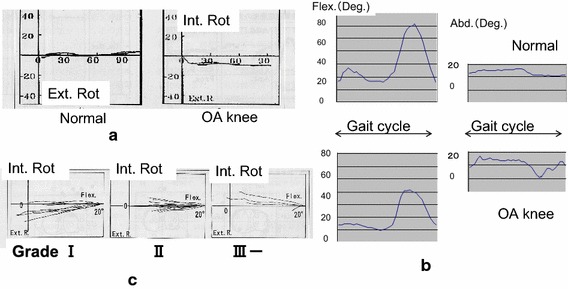
Results of 3D motion analysis of OA knee. a Screw-home motion clearly detected in normal subjects. b Using gait analysis of OA patients, lateral thrust was detected as an acute adduction with decreased double knee flexion. c Screw-home motion was diminished by the progression of OA
Fig. 3.
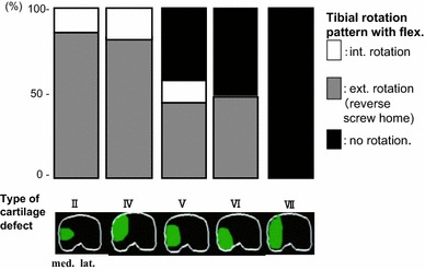
Relation between the knee motion (rotation) and defects of tibial articular surfaces of TKA patients, preoperatively
Clinical results and motion analysis of high tibial osteotomy were compared before and after osteotomy [8]. Preoperatively, most of the patients showed lateral thrust, which disappeared in most patients after osteotomy. Consequently, a few patients showed SHM, but after osteotomy none showed SHM and some patients tended to have reverse SHM. Therefore, we concluded that the thrust is mainly related to change of the weight-bearing axis, but rotation seemed to be more related to joint congruity which was not changed by osteotomy, and this was aggravated by time.
A long-term follow-up study of resection interposition arthroplasty was carried out. Typical progression of radiographic images of a case in which the knee was fused at age 6 is presented. Resection interposition arthroplasty was performed at 14 years of age. Twenty-six years after the interposition arthroplasty she maintained 90° range of knee motion without pain (Fig. 4). Radiographic image findings can be summarized as: (1) concavity of tibial joint surface has been osteotomized to be flat, (2) low patella (i.e., patella infera), and (3) enlargement of posterior part of condyle (Fig. 5). The joint surface evolution, without the cruciate ligaments, seemed to be created by mono-centric motion. Rotational change can be detected by the trajectory of a helical axis. The helical axis of TKA is more similar to that of resection arthroplasty than a normal knee. This suggests that the rotation of the knee joint is more related to the geometry of the joint surface (Fig. 6).
Fig. 4.
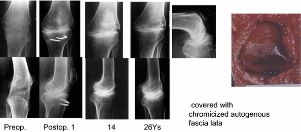
40-year-old female, a succession of X-rays showing resection-interposition arthroplasty, performed at 14 years of age, to her fused knee suffering from tuberculosis arthritis
Fig. 5.
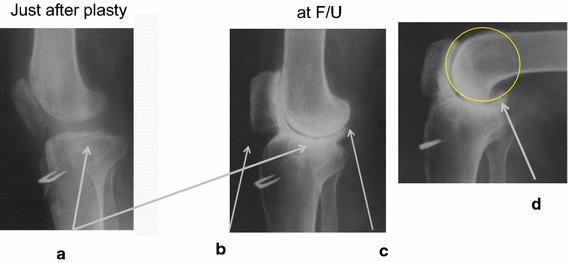
Typical X-ray findings of resection arthroplasty. a Concavity of tibial joint surface, b low-placed patella, c enlargement of posterior part of condyle, d circular remodeling
Fig. 6.
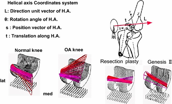
Trajectory of helical axis. Rotational change detected by helical axis: screw-home motion of normal subject is quite different from reverse SHM of severe OA patient. Helical axis of TKA is similar to resection arthroplasty
The main factors related to motion after TKA are joint geometry, osteotomy level and soft tissue tension. For monitoring soft tissue tension, gap measuring is widely accepted. Instead of measuring the flexion gap between 90° flexion and full extension, an intraoperative motion analysis was attempted.
Intraoperative analysis of the trial components estimated by contact area via 6DOF photometric system
We have established a system to measure knee joint motion intraoperatively using LEDs rigidly mounted to the femoral and tibial trial components. The 3D positions of the LEDs were detected by linear CCD cameras (Fig. 7). By combining surface models of the trial components and the kinematic data from the LEDs, the inter-surface relationship of the components during passive knee motion was obtained. Inter-surface proximity was evaluated by the distance between every point of the tibial surface and the closest point of the opposing femoral surface to estimate the contact point (ECP). The trajectory of ECPs for cases using the Genesis II prosthesis, (Smith & Nephew Orthopedics, Memphis, TN) presented two patterns, straight FRB and paradoxical roll-back, that is anterior translation during flexion (Fig. 8). The joint line (femoral distal and posterior osteotomy and tibial osteotomy) for the cases with these intraoperative measurements was assessed by lateral X-ray. Levels of osteotomy for the cases with the straight FRB were lower on the femoral side and higher on the tibial side compared with those with the paradoxical translation [9]. We concluded that decreased tension in the retained PCL was related to paradoxical translation. Further, in order to evaluate knee motion after TKA, the assessment of component position is essential.
Fig. 7.
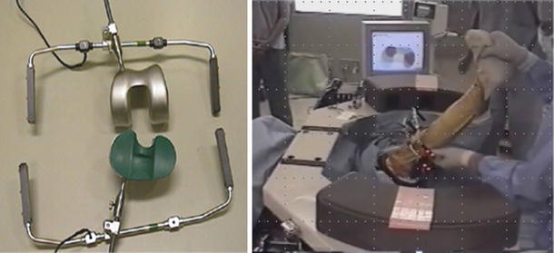
Photometric system of measurement. The position of all LEDs were detected in three-dimensions by two sets of three linear CCD cameras
Fig. 8.
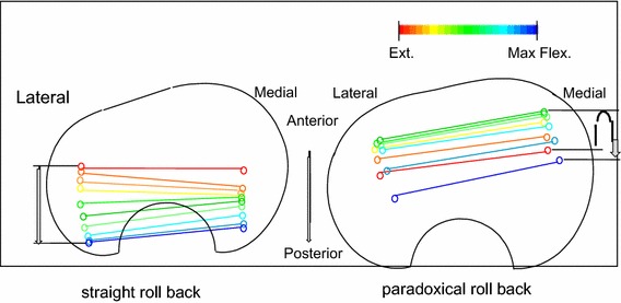
Trajectory of helical axis photometric system of measurement. Two types of motion: straight roll-back and paradoxical roll-back presenting anterior translation during flexion
3D leg alignment assessment and its application to TKA
A system of 3D leg alignment assessment using biplanar X-ray of the entire lower extremity with the subjects in a standing position was developed. The accuracy of this system had been improved by incorporating a camera calibration procedure and 3D image-fitting of the bone model created from a CT scan [10]. An automatic construction of an anatomical coordinate system based on a CT bone model was developed [11]. The femoral coordinate system was created by the contour tracking obtaining the outlines of both posterior condyles and femoral head, approximated as spheres. As for the tibial side, contour tracking to obtain the largest outline approximated an ellipse. For assessing the position of components, automated image registration was also developed [12]. After digitization of several bony landmarks such as the epicondylar axis, posterior condylar line on the femoral side, and Akagi’s line on the tibial side, an anatomical assessment including mechanical axis, femoral or tibial torsion etc. are automatically presented. Assessment of the position of components can be calculated by any organized coordinates system by transformation, while retaining the data of individual anatomical variance. Positions and sizes of components can be planned by fitting the 3D model of a component to the bone model image, by assessing the position using an anatomical coordinate system. Post-operative biplanar X-ray is taken in the same manner. The same anatomical coordinates system is established by image fitting of the preoperative bone model. By automatically matching the image of the component model, 3D position assessment can also quantitatively calculate the joint level (Fig. 9) [13]. For the femur, the distal joint line is defined by the coordinate Z-axis of the most distal point of the medial and lateral condyles and components. And the posterior joint line is defined by the coordinate Y-axis of the most posterior points of the medial and lateral condyles. For the tibial side, the joint level can be defined by the coordinate Z-axis of the medial and lateral sides.
Fig. 9.
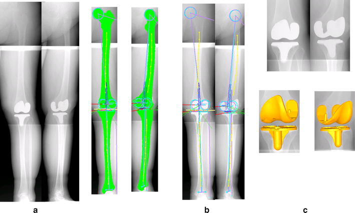
Three-dimensional assessment of position. a Postoperative biplanar X-ray, b anatomical coordinates system by image fitting of preoperative bone model, c automatic image matching of 3D model of component to be used
3D knee motion analysis by fluoroscopy with a 2D–3D image of the tibial component, using the insert matching procedure starts with the knee in full extension. Then, matching proceeds to the femoral component using 3D relative positions between both components obtained from post-operative assessment, which has been chosen as the reference position for improvement of accuracy. The procedure is repeated for the complete series of X-ray views. Both ECP and femur motion can be determined by the change of skeletal references such as epicondyle axis or geometric center axis.
The 2D–3D image matching procedure of TKA kinematics analysis
The study of the kinematics of the human knee in vivo using a 2D–3D registration technique is now an important and fully accepted method [14, 15]. Numerous studies have been reported regarding motion based on specifics of design such as condylar offset, using parameters such as the amount and direction of rotation, FRB, postoperative range of motion and the condylar lift-off phenomenon. After TKA, FRB is similar to the normal knee when using a PS-type design, but in some CR designs a different pattern of paradoxical anterior translation has been seen. A “medial pivot” motion like the normal pattern has been seen, but usually decreased in amount, and in some studies a reverse axial rotation was seen. The reduced rotation may be related to the high constraint of the design, increased tension of the PCL, or perhaps both [16–18].
PS designs achieve more flexion than CR designs, and this may be related to the amount of FRB. Posterior condylar offset (PCO) is also considered to be an important factor [19]. Banks [20] demonstrated a relationship suggesting that 1 mm of posterior offset gives 1.4° of increased flexion, based on data from a multicenter study. Ishii [21] reported that the joint line level set by our method on either the medial or the lateral side had no effect on postoperative flexion, with or without the PCL. Many factors, such as preoperative flexion, rehabilitation, surgical technique etc. are related to the ultimate flexion angle, but preoperative range is the strongest predictor.
Gejo [22] compared preoperative ROM to postoperative ROM by monitoring intraoperative tension in the patellar tendon with a strain gauge. Patellar tendon tension was related to preoperative flexion angle and an inter-operative tight flexion gap and postoperative flexion gain.
Clinical evidence of a compression fracture of the posterior condyle as a complication of quadriceps-plasty for contracted knee demonstrates this relationship. Manual flexion force applied after release of intra-capsular adhesion and quadriceps muscle in some cases showed the tibia translating minimally posteriorly with the femur remaining on the tibial joint surface with a hinge-like motion leading to a compression fracture of the posterior condyle. These suggested that the amount of FRB and tight quadriceps tension are related to limited motion (Fig. 10).
Fig. 10.
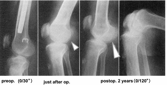
Compression fracture of posterior condyle. During a quadriceps plasty for contracted knee, a compression fracture of the posterior condyle took place because there was no femoral rollback. The depression site seemed to be gradually remodeled by regained motion
A cam-post mechanism has been developed to model FRB. Some investigators have evaluated the contact position of the cam-post mechanism [23, 24]. The contact area moves on the tibial post and can be concentrated on the anterior part in full extension or at the base in deep flexion. The timing during the motion cycle of this engagement differs based on the cam-post design. These findings suggest that high stresses could result in failure of the post.
There is also concern that the condylar lift-off phenomenon, presenting as a tilting between components, could lead to polyethylene failure by cracking. A high rate of lift-off has been reported during gait analysis, with over 90 % demonstrating this motion at heel strike, and 70 % of CR types and 80 % of PS types in deep flexion [25]. This lift-off is thought to be related to the rotation position of components, and this rate of lift-off is decreased when rotation of the femoral component is aligned to the TEA [26].
Our 3D motion analysis allows us to observe any section of the knee components as a slice view on a computer display. The femoral component sometimes showed tilt in the frontal view in flexion. We have seen in this slice view that the femoral component contacts the polyethylene insert medially but is not in contact with the insert laterally, seemingly demonstrating lift-off. However, observation of the same motion in the sagittal plane shows the femoral component contacting the deepest part of the concave tibial insert and, on the medial side, there is contact with the anterior higher part of the insert. Even if the tibial insert has a convex form, rotation of femoral component creates this effect (Fig. 11). So, the tilting does not always mean lift-off but should be recognized as abnormal motion in some cases.
Fig. 11.
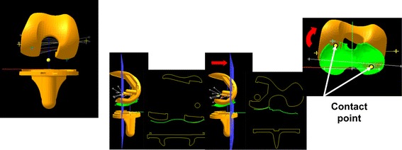
“Lifting” of femoral component. Using a slice view at the posterior condyle, it can be seen that the femoral component contacts the polyethylene insert medially but apart from the insert, there was lateral lift-off. Even if the tibial insert has a convex form, internal rotation of the femoral component creates this inclination
Motion analysis of TKA kinematics by 2D–3D image matching or motion capture has limitations, such as the selection of subjects, level of satisfaction of patients and procedures done by many surgeons, often with limited information about preoperative function and postoperative position of prosthetic components. Joint geometry of the posterior condyle, as an essential element of kinematic data, means a combination of the shape of the femoral component combined with its position on the femur. These combined parameters effect to joint gap, balance and alignment, thus causing the motion change and motion analysis between components cannot explain the relationship of these factors.
Evaluation of in vivo dynamic kinematics by trajectory of trans-epicondylar axis (TEA)
OA patients with an Advance® Medial Pivot Knee system (Wright Medical Technology, Memphis, TN), which has a single spherical radius of the femoral component, were examined by a 3D alignment study. The size and position of implant installation for surgery were selected by 3D preoperative planning. After planning, a simulation of IM rod insertion into a bone model was performed to determine an entrance point and angles of osteotomy relative to the rod. During surgery, a special cutting jig was used to connect to the IM rod at an angle determined by the simulation (Fig. 12). 3D alignment and motion analysis were completed postoperatively.
Fig. 12.
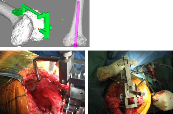
Operative procedure. Simulation of IM rod insertion: an entrance point for the IM rod and angles of osteotomy plane to the rod to set the special cutting jig are determined
The TEA was utilized as a parameter for TKA kinematics [27]. Relative motion of the femur compared to the tibia was described and quantified as the movement of the TEA projected onto the axial (X–Y) plane of the tibial coordinate system. Motion was evaluated by determining the antero-posterior (A-P) translations of medial and lateral ends of the TEA of all projected TEAs on the tibial axial plane (Fig. 13). The vertical translation of the TEA to the medial and lateral sagittal planes of the midline of the tibial joint surface was calculated. Paradoxical motion and poor A-P translation (<5 mm) on the lateral side were defined as abnormal. Maximum vertical translation more than 5 mm was defined as abnormal (Fig. 14). All cases demonstrated the medial pivot pattern. There was no relationship between component position with normal and abnormal motion because there were no outliers using the simulation technique. However, in assessing the 3D joint line there was no case with normal motion pattern in cases in which the PCO decreased or increased more than 2 mm. Paradoxical motion seemed to be related to decrease of PCO on both the medial and lateral sides. Decrease of PCO on the medial side was related to maximum vertical translation. In cases with decreased PCO on both medial and lateral sides there was decreased amount of FRB, explained by the very large flexion gap that created instability during mid to deep flexion. Decreased medial PCO with an increase in the maximum vertical translation seemed to be caused by a discrepancy of motion center and TEA where collateral ligaments attached. In this circumstance clinically, a desirable balance in total range of motion would not be expected (Fig. 15). This shows an inherent limitation of TKA; that is component geometry does not fully cover the anatomical variability of patients. From this study of the relation of motion to the position of components, we suggest that, to avoid condylar lift-off, assure that the rotation of the femoral component is aligned with the TEA.
Fig. 13.
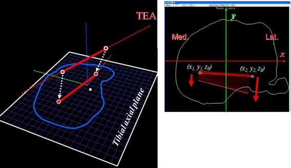
Trans-epicondylar axis as a parameter of motion analysis. Relative motion of the femur compared to the tibia: described and quantified as the movement of the TEA projected onto the axial (X–Y) plane of the tibial coordinate system
Fig. 14.
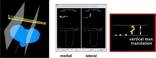
Vertical translation of the TEA at medial and lateral sagittal plane of midline of tibial joint surface
Fig. 15.
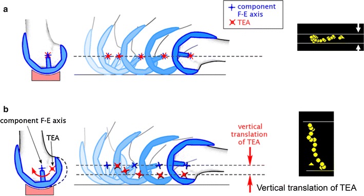
Maximum vertical translation and motion. a TEA close to component axis, b discrepancy between motion center and TEA
Abnormal motion and condylar lift-off may adversely affect the longevity of TKA. From kinematic data, simulation of contact stresses has been attempted by many investigators. Still, there is no clear target of motion for TKA. We believe that the preferable motion of a TKA should be determined in part by the motion of the knee before implantation.
OA knee motion analysis—considering the target of TKA kinematics
We have conducted an epidemiological study for over 30 years to detect the incidence and risk factors of OA knees [28]. Medial OA has been shown to be significantly related to varus deformity, flexion contracture of the knee, limitation of hip internal rotation indicating a shift in the center of hip rotation externally, and a toe-out gait pattern. These postural changes suggest that varus knee deformity results from alteration in the linkage of the entire lower extremity. It is clear that the kinematic changes in the OA knee, such as thrust, toe-out gait and decrease of double knee, are a succession of cascade effects, categorized by the progression of OA X-ray grades.
It is important to recognize the mechanism of SHM. By evaluating the movement of trajectory of the TEA projected onto the tibial axial plane it is clear that in the normal subject there is a medial pivot in the SHM. The amount of SHM is decreased and shifted posteriorly in ACL deficiency and SHM is reversed in patients with OA (Fig. 16).
Fig. 16.
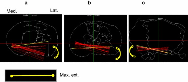
Movement of the TEA projected onto tibial axial, a normal subject, b ACL-deficient knee, c OA patient
There is no explanation for the pathological mechanism of reverse SHM reported in the literature. The suggested mechanism of SHM is (1) osseous factor: the femoral anatomical axis is shifted laterally about 6° from the axis of the knee joint, internally rotated about 20° toward the hip and externally rotated about 25° toward the ankle; (2) geometry of joint surface: about 30° internal rotation of a front part of medial condyle; and (3) soft tissue tension: the passive tension of ACL and lateral pull from quadriceps attachment. In theory, the plane of motion of the hip, knee and ankle should be aligned in the frontal plane: through SHM the motion plane of knee, ankle and hip joint are regulated to be aligned in the frontal aspect [29]. With progression of OA, the hip and ankle tend to rotate externally as shown in our epidemiological study. To be properly aligned to the motion plane in the frontal aspect, the knee should rotate internally because the knee joint has freedom of rotation to correct the motion plane (Fig. 17).
Fig. 17.
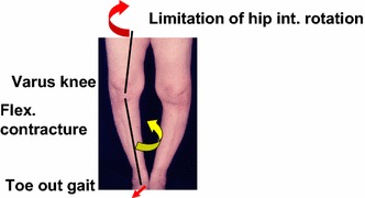
Postural change from varus knee deformity and its relation to reverse screw-home motion. OA knee alignment tends to rotate externally. This correlates with flexion contracture of knee, limitation of hip internal rotation, and a toe-out gait pattern. This can be compensated by internal knee rotation (reverse screw-home) at the knee joint
Summary — suggestions for future knee kinematic study
Motion analysis methods will improve and provide much more information about the knee. Each patient has a unique preoperative knee function and motion. TKAs, as they exist today, provide a new joint surface and good alignment, but the soft tissue is not optimized for joint kinematics, as evidenced by the considerable difference from normal of the patho-mechanism of reverse SHM. Determining motion by the trajectory of the TEA, not by components, provides better information. Future researchers should evaluate not only 3D knee motion but also the mechanisms that cause the motion.
Acknowledgments
I thank the Niigata Biomechanics Research Group for participation in and facilitation of these studies over the past 30 years; Profs. Yuji Tanabe, Makoto Sakamoto, Toyohiko Hayashi and their staff of Faculty of Engineering; Drs. Go Omori, Yoshinori Ishii, Takashi Sato, Takayuki Murayama, and other staff of the Knee Research Group, Department of Orthopedic Surgery, Niigata University; and Prof. Ramon B. Gustilo (University of Minnesota), and Prof. John D. Blaha (University of Michigan) for their support.
Conflict of interest
No benefits or funds were received in support of the study.
References
- 1.Parratte S, Pagnano MW, Trousdale RT, Berry DJ. Effect of postoperative mechanical axis alignment on the fifteen-year survival of modern, cemented total knee replacements. J. Bone Joint Surg Am. 2010;92(12):2043–2049. doi: 10.2106/JBJS.I.01398. [DOI] [PubMed] [Google Scholar]
- 2.Bourne RB, Chesworth BM, Davis AM, Mahomed NN, Charron KD. Patient satisfaction after total knee arthroplasty: who is satisfied and who is not? Clin Orthp Relat Res. 2009;468(1):57–63. doi: 10.1007/s11999-009-1119-9. [DOI] [PMC free article] [PubMed] [Google Scholar]
- 3.Grood ES, Suntay WJ. A joint coordinate system for the clinical description of three-dimensional motions: application to the knee. J Biomech Eng. 1983;105(2):136–144. doi: 10.1115/1.3138397. [DOI] [PubMed] [Google Scholar]
- 4.Nilsson KG, Kärrholm J, Ekelund L. Knee motion in total knee arthroplasty. A roentgen stereophotogrammetric analysis of the kinematics of the Tricon-M knee prosthesis. Clin Orthop Relat Res. 1990;256:147–161. [PubMed] [Google Scholar]
- 5.Koga Y. Three-dimensional knee motion analysis for the pathogenesis of knee osteoarthritis. Biomed Mater Eng. 1998;8:197–205. [PubMed] [Google Scholar]
- 6.Ishii Y, Terajima K, Terashima S, Koga Y. Three-dimensional kinematics of the human knee with intracortical pin fixation. Clin Orthop Relat Res. 1997;343:144–150. [PubMed] [Google Scholar]
- 7.Ishii Y, Terajima K, Koga Y, Bechtold JE. Screw home motion after total knee replacement. Clin Orthop Relat Res. 1999;358:181–187. [PubMed] [Google Scholar]
- 8.Takemae T, Omori G, Nishino K, Terajima K, Koga Y, Endo N. Three-dimensional knee motion before and after high tibial osteotomy for medial knee osteoarthritis. J Orthop Sci. 2006;11(6):601–606. doi: 10.1007/s00776-006-1066-1. [DOI] [PubMed] [Google Scholar]
- 9.Omori G, Nishino K, Suzuki Y, Segawa H, Hayashi T, Koga Y. Intraoperative measurements of knee motion in total knee arthroplasty. Knee. 2003;10(1):75–79. doi: 10.1016/S0968-0160(02)00062-5. [DOI] [PubMed] [Google Scholar]
- 10.Sato T, Koga Y, Omori G. Three-dimensional lower extremity alignment assessment system: application to evaluation of component position after total knee arthroplasty. J Arthroplast. 2004;19(5):620–628. doi: 10.1016/j.arth.2003.12.063. [DOI] [PubMed] [Google Scholar]
- 11.Kai S, Sato T, Koga Y, Omori G, Kobayashi K, Sakamoto M, Tanabe Y. Automatic construction of an anatomical coordinates system for three-dimensional bone models of the lower extremities—pelvis, femur, and tibia. J. Biomech. 2014;47(5):1229–1233. doi: 10.1016/j.jbiomech.2013.12.013. [DOI] [PubMed] [Google Scholar]
- 12.Kobayashi K, Sakamoto M, Tanabe Y, Ariumi A, Sato T, Omori G, Koga Y. Automated image registration for assessing three-dimensional alignment of entire lower extremity and implant position using bi-plane radiography. J Biomech. 2009;42(16):2818–2822. doi: 10.1016/j.jbiomech.2009.08.022. [DOI] [PubMed] [Google Scholar]
- 13.Sato T, Koga Y, Sobue T, Omori G, Tanabe Y, Sakamoto M. Quantitative 3-dimensional analysis of preoperative and postoperative joint lines in total knee arthroplasty: a new concept for evaluation of component alignment. J Arthroplast. 2007;22(4):560–568. doi: 10.1016/j.arth.2006.06.020. [DOI] [PubMed] [Google Scholar]
- 14.Dennis DA, Komistek RD, Hoff WA, Gabriel SM. In vivo knee kinematics derived using an inverse perspective technique. Clin Orthop Relat Res. 1996;331:107–117. doi: 10.1097/00003086-199610000-00015. [DOI] [PubMed] [Google Scholar]
- 15.Banks SA, Markovich GD, Hodge WA. In vivo kinematics of cruciate-retaining and -substituting knee arthroplasties. J Arthroplast. 1997;12(3):297–304. doi: 10.1016/S0883-5403(97)90026-7. [DOI] [PubMed] [Google Scholar]
- 16.Banks SA, Hodge WA. Implant design affects knee arthroplasty kinematics during stair-stepping. Clin Orthop Relat Res. 2004;426:187–193. doi: 10.1097/01.blo.0000138956.04316.ac. [DOI] [PubMed] [Google Scholar]
- 17.Dennis DA, Komistek RD, Mahfouz MR, Walker SA, Tucker A. A multicenter analysis of axial femorotibial rotation after total knee arthroplasty. Clin Orthop Relat Res. 2004;428:180–189. doi: 10.1097/01.blo.0000148777.98244.84. [DOI] [PubMed] [Google Scholar]
- 18.Komistek RD, Mahfouz MR, Bertin KC, Rosenberg A, Kennedy W. In vivo determination of total knee arthroplasty kinematics: a multicenter analysis of an asymmetrical posterior cruciate retaining total knee arthroplasty. J Arthroplast. 2008;23(1):41–50. doi: 10.1016/j.arth.2007.01.016. [DOI] [PubMed] [Google Scholar]
- 19.Bellemans J, Banks S, Victor J, Vandenneucker H, Moemans A. Fluoroscopic analysis of the kinematics of deep knee flexion in TKA. Influence of posterior condylar offset. J Bone Joint Surg Br. 2002;84(1):50–53. doi: 10.1302/0301-620X.84B1.12432. [DOI] [PubMed] [Google Scholar]
- 20.Banks S, Bellemans J, Nozaki H, Whiteside LA, Harman M, Hodge WA. Knee motions during maximum flexion in fixed and mobile-bearing arthroplasties. Clin Orthop Relat Res. 2003;410:131–138. doi: 10.1097/01.blo.0000063121.39522.19. [DOI] [PubMed] [Google Scholar]
- 21.Ishii Y, Noguchi H, Takeda M, Sato J, Toyabe S. Posterior condylar offset does not correlate with knee flexion after TKA. Clin Orthop Relat Res. 2013;471(9):2995–3001. doi: 10.1007/s11999-013-2999-2. [DOI] [PMC free article] [PubMed] [Google Scholar]
- 22.Gejo R, Morita Y, Matsushita I, Sugimori K, Watanabe H, Kimura T. Intraoperative patellar tendon strain: predicting the range of knee flexion after total knee arthroplasty. J Orthop Sci Jan. 2009;14(1):51–55. doi: 10.1007/s00776-008-1286-7. [DOI] [PubMed] [Google Scholar]
- 23.Zingde SM, Leszko F, Sharma A, Mahfouz MR, Komistek RD, Dennis DA. In vivo determination of cam-post engagement in fixed and mobile-bearing TKA. Clin Orthop Relat Res. 2014;472(1):254–262. doi: 10.1007/s11999-013-3257-3. [DOI] [PMC free article] [PubMed] [Google Scholar]
- 24.Andriacchi TP, Dyrby CO, Johnson TS. The use of functional analysis in evaluating knee kinematics. Clin Orthop Relat Res. 2003;410:44–53. doi: 10.1097/01.blo.0000062383.79828.f5. [DOI] [PubMed] [Google Scholar]
- 25.Dennis DA, Komistek RD, Walker SA, Cheal EJ, Stiehl JB. Femoral condylar lift-off in vivo in total knee arthroplasty. J Bone Joint Surg Br. 2001;83(1):33–39. doi: 10.1302/0301-620X.83B1.10632. [DOI] [PubMed] [Google Scholar]
- 26.Scuderi GR, Komistek RD, Dennis DA, Insall JN. The impact of femoral component rotational alignment on condylar lift-off. Clin Orthop Relat Res. 2003;410:148–154. doi: 10.1097/01.blo.0000063603.67412.ca. [DOI] [PubMed] [Google Scholar]
- 27.Tanifuji O, Sato T, Kobayashi K, Mochizuki T, Koga Y, Yamagiwa H, Omori G, Endo N. Three-dimensional in vivo motion analysis of normal knees employing transepicondylar axis as an evaluation parameter. Knee Surg Sports Traumatol Arthrosc. 2013;21(10):2301–2308. doi: 10.1007/s00167-012-2010-x. [DOI] [PubMed] [Google Scholar]
- 28.Koga Y. Epidemiological study. In: Koga Y, editor. Osteoarthritis of the knee–epidemiology and biomechanics. Tokyo: Nanko-Do; 2008. pp. 42–65. [Google Scholar]
- 29.Neumann DA. Chapter 13 Knee. In: Neumann DA, editor. Kinesiology of the musculoskeletal system: foundations for physical rehabilitation. 2. St. Louis: Mosby Inc; 2010. pp. 520–72. [Google Scholar]


