Abstract
The dependence of single-molecule photoluminescence intermittency (PI) or “blinking” on the local dielectric constant (ε) is examined for nile red (NR) in thin films of poly(vinylidene fluoride) (PVDF). In previous studies, variation of the local dielectric constant was accomplished by studying luminophores in chemically and structurally different hosts. In contrast, the NR/PVDF guest–host pair allows for the investigation of PI as a function of ε while keeping the chemical composition of both the luminophore and host unchanged. The solvatochromic properties of NR are used to measure the local ε, while fluctuations in NR emission intensity over time provide a measure of the PI. PVDF is an ideal host for this study because it provides submicron-sized dielectric domains that vary from nonpolar (ε ≈ 2) to very polar (ε ≈ 70). The results presented here demonstrate that the local dielectric environment can have a pronounced effect on PI. We find that the NR emissive events increase 5-fold with an increase in ε from 2.2 to 74. A complex dependence on ε is also observed for NR nonemissive event durations, initially increasing as ε increases from 2.2 to 3.4 but decreasing in duration with further increase in ε. The variation in emissive event durations with ε is reproduced using a photoinduced electron-transfer model involving electron transfer from NR to PVDF. In addition, an increase in NR photostability with an increase in ε is observed, suggesting that the dielectric environment plays an important role in defining the photostability of NR in PVDF.
Introduction
Single-molecule (SM) spectroscopic techniques are routinely used to study the structure and dynamics of complex materials.1−4 A current challenge in SM spectroscopy is identifying the guest–host interactions that influence SM phenomena such as photoluminescence intermittency (PI). Investigations of PI generally involve measuring the distributions of emissive (on) and nonemissive (off) event durations under different environmental conditions, and correlating changes in environment with changes in these distributions.2,5 Emissive and nonemissive event durations can often span multiple decades in time and are often assumed to be power-law distributed, although these claims are now under dispute.6−10 Nevertheless, power-law distributions (and their distributional relatives) can arise when the rate constants for populating and depopulating a nonemissive or “dark” state evolve over the course of the measurement.7
For organic luminophores, a common model for dark-state formation is the production of the radical form of the luminophore through photoinduced electron transfer to the surrounding environment. In this model for PI, a distribution of electron-transfer sites or energy barriers is presumed to exist within the host, providing for a corresponding distribution of electron-transfer rate constants.3,7,11,12 Also inherent in this model for PI is the expectation that the electron-transfer rate constant will depend on the local dielectric constant (ε).13 The relationship between ε and PI has been explored by others, who proposed that an increase in the host dielectric constant serves to stabilize the charge-separated state, resulting in prolonged nonemissive event durations. For single terrylene molecules14 as well as semiconducting nanocrystals,15 the nonemissive event duration distributions shift to longer times with increased ε, consistent with electron transfer being responsible for the PI exhibited by these emitters.
Recently, there has been renewed interest in exploring the relationship between PI and ε for semiconductor nanocrystals.16 However, a complicating issue with these studies is that variation in ε was accomplished by changing the chemical composition of the host, including their fundamental solvation properties.14,15 In our recent study of nile red (NR) in poly(vinylidene fluoride) (PVDF), we found that polymer films expressed in the ferroelectric (β) phase consist of a wide distribution of dielectric environments ranging from ε ≈ 2 to 70.17 Using the solvatochromic shift of NR, which extends from 520 nm in hexane (ε = 1.88) to 614 nm in acetonitrile (ε = 37.5), we were able to spatially map the dielectric environments of PVDF with domains sizes ranging from a few hundred nanometers to microns in diameter.18 This finding suggests that the NR/PVDF guest–host system provides a novel opportunity to investigate the dependence of PI on the local environment without varying the chemical composition of the luminophore or host.
Here, we present a study where both the intensity and emission energy from single NR molecules is measured as a function of time, allowing for the simultaneous measurement of PI and the local dielectric constant of the environment. We find that for NR in PVDF, the median emissive event durations increase 5-fold with an increase in ε from 2.2 to 74. A more complex dependence on ε is observed for NR nonemissive event durations, with the median nonemissive event duration initially increasing as ε increases from 2.2 to 3.4, but then decreasing in duration as ε continues to increase. Employing the photophysical properties of NR and PVDF, we have constructed a simple model for the photoinduced electron transfer between NR and PVDF. Using this model, the variation in emissive event durations with ε is reproduced. In addition, the photostability of NR increases with ε, suggesting that the local dielectric environment plays an important role in defining the photostability of NR in PVDF.
Experimental Section
Sample Preparation
Thin films of nile red (NR, Aldrich, 99+% pure by LC-MS) embedded in poly(vinylidene fluoride) (PVDF, Sigma-Aldrich, MW ≈ 534 000 by GPC) were prepared as described previously.18 Films were ∼300 nm thick as determined by ellipsometry, with sample preparation tailored to express the ferroelectric β phase of PVDF, as described in the literature.19 Heavily dyed samples demonstrated no degradation in fluorescence intensity or optical density over periods of months.
Microscopy
SM emission was collected on an inverted scanning fluorescence confocal microscope described elsewhere.18 The 488 nm (Novalux, Protera) excitation field was circularly polarized using a λ/4 waveplate to excite all dye orientations within the films. An excitation power of 3 μW, as measured at the entrance port of the microscope, was employed, and SMs were located by raster scanning the film across the objective (Nikon, Plan-Fluor) focal volume in 100 nm steps. The emission was split by a 600 nm short-pass dichroic mirror, with the reflected (R) and transmitted (T) fields focused onto two separate avalanche photodiode detectors (APD, PerkinElmer SPCM-AQR-16). An overall emissive intensity threshold of 500 counts per 100 ms was used to trigger automated data collection for 150 s with a bin time of 5 ms.
Data Collection and Analysis
SM PI data were first assessed for overall emissive intensity employing a threshold of 12 counts per 5 ms bin, corresponding to three standard deviations above the background. PI traces were visually examined, and only those demonstrating emissive “activity” for at least 20 s were analyzed. In addition, only data from molecules demonstrating >500 nm separation and single step photodecomposition were included in our analysis. An overall reflected/transmitted ratio (R/T) value was calculated by summing photons on each detector for time points where the sum of the two channels exceeded the threshold and then dividing to obtain the time-averaged ratio for emissive events. The data were then categorized into five R/T categories (defined in Table 1) as determined for this optical configuration previously.18 Data were collected until at least 100 molecules populated each R/T category.
Table 1. Data Summary for Initial Data Collection and Sorting before Categorizing Based on the BDIC Algorithm.
| R/T group | wavelength range (nm) | range of ε | total molecules | nonblinking (%)a | discardedb | final sample size |
|---|---|---|---|---|---|---|
| 0.5 and below | <560 | <2.8 | 148 | 16 (11%) | 3 | 129 |
| 0.5–1 | 560–588 | 2.8–4.2 | 374 | 61 (16%) | 3 | 310 |
| 1–1.5 | 588–606 | 4.2–21 | 220 | 36 (16%) | 3 | 181 |
| 1.5–2 | 606–614 | 21–47 | 105 | 25 (23%) | 1 | 79 |
| 2 and above | >614 | >47 | 176 | 53 (30%) | 1 | 122 |
| total | 1023 | 191 (18%) | 11 | 824 |
Number of molecules without nonemissive events (nonblinking).
Molecules that had no emissive information (immediate photodecomposition).
The PI data were analyzed by identifying change points in emissive intensity using the Bayesian detection of intensity changes method (BDIC; see the Supporting Information) reported by Ensign and Pande.20 This approach represents an evolution of the maximum likelihood change point detection (CPD) algorithm previously employed in our laboratory.21 The BDIC algorithm has one adjustable level of sensitivity, negating the need for look-up tables and error matrices. BDIC also demonstrates greater accuracy at locating change points; however, neither CPD nor BDIC is able to capture short emissive events (10–30 ms) present within long nonemissive segments due to the overwhelming number of background counts relative to a few bins of signal. To detect these emissive bursts, the analysis searches for additional emissive events within long nonemissive segments (below the intensity threshold of 12 counts per bin) defined as exceeding 5 s in duration. A burst is defined as a segment with intensity greater than five standard deviations above the mean nonemissive intensity within the segment in question. In addition, bursts must span at least 10 ms.
Once change points were detected, intensity states greater than two standard deviations above the root-mean-square noise (9 counts/5 ms) were designated as emissive, and those below were designated as nonemissive. An emissive duration is defined as the total time that the molecule’s intensity exceeds the emissive threshold, with a corresponding definition used for nonemissive durations. Through comparison with the initial sorting threshold of 12 counts/5 ms, we found that the results are not impacted by choice of threshold. The BDIC algorithm calculates the average intensity between change points, thereby eliminating spurious crossings caused by noise. The 95% threshold employed avoids confusing low-intensity emissive segments with nonemissive events. Molecules that exhibited at least two emissive periods and at least one nonemissive period before photodecomposition were accepted as “blinking” and are included in the final data set.
The conversion of R/T values to the wavelength of the emission maximum has been described in detail elsewhere.18 Briefly, a mapping of the R/T ratio to emission wavelength maxima was performed by convolving ensemble NR fluorescence emission spectra in hexane, toluene, and acetonitrile with the APD efficiency curves, the emission filter transmission curve, and the 600 nm dichroic reflectance and transmission curves to calculate the expected reflected (R) and transmitted (T) spectra.11 By numerically shifting the solvent spectra and combining them to calculate a hybrid curve that takes into account the emission line shape of NR in solvents of differing polarity, the R/T ratio was transformed to the emission wavelength maximum (λem) of NR. This wavelength was then converted to energy. Finally, the relationship between energy and dielectric constant was established using the solvatochromic properties of NR. A plot of the emission energy max of NR in these solvents versus the known dielectric constant (Figure 1) was fit to a two-term exponential function that provides a conversion from emissive energy to the dielectric constant.18
| 1 |
Figure 1.
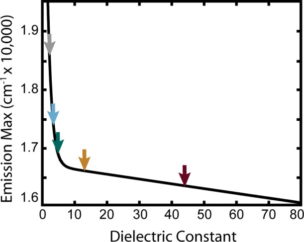
Fluorescence maximum of NR (in wavenumbers) versus the dielectric constant. The solid line corresponds to eq 1. Arrows indicate the dielectric constant and average energy of the dielectric categories discussed in the text (shown here are five of the eight categories); ε1 = 2.2 (gray), ε2 = 3.4 (cyan), ε3 = 4.8 (teal), ε4 = 13 (orange/brown), and ε5 = 44 (dark red). The origin of this relationship is discussed in detail in our previous work.18
Analysis of the emissive and nonemissive event durations begins with the construction of cumulative distribution functions (CDFs), defined to be the probability that an observed event duration is between tmin and t, and is zero for t < tmin and one for t greater than the longest event duration. The method of converting probability distribution functions (PDFs) to CDFs was described previously.9 The CDF is related to the PDF through an integral and bound by zero when t < tmin and by one at the longest observation time.
| 2a |
The CDF can also be calculated directly from the PI data through the correspondence of integrals to sums by counting events with duration ti less than time t for all N events
| 2b |
Similarly, the complementary CDF is defined as
| 3 |
The complementary CDF is helpful when visualizing PI data as the majority of the event durations occur at short times.
Results
Table 1 provides a summary of the R/T distributions for NR molecules embedded in PVDF. This table is representative of the inherent distribution of NR environments provided by PVDF. The table demonstrates that approximately half of the NR molecules reside in dielectric domains where ε < 4.2. Table 1 also shows that the number of molecules that do not demonstrate PI (that is, molecules that continuously emit) increases as the dielectric constant of the environment increases.
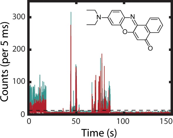
A representative PI trace for a single NR molecule embedded in PVDF is presented in Figure 2. Overlaid on the total intensity is the result of the BDIC algorithm, illustrating the detected intensity levels. Consistent with previous results, the SM trajectories depict a distribution of intensity levels.2 Figure 2a shows the intensities of the individual transmitted and reflected channels that demonstrate temporal variation in the NR emission energy maximum. The ratios of reflected (R) intensities divided by transmitted (T) intensities were used to calculate the emission energies of intensity segments identified by the BDIC algorithm lying above the emissive threshold. The data were then reduced by sorting the SMs by the time-averaged dielectric constant and divided into 8 dielectric categories of 100 molecules. By averaging over the entire emissive trace, we avoid overanalyzing instantaneous changes in the emission energy that may be caused by spontaneous fluctuations in the local polarity. These categories provide a basis for the analysis of PI as a function of ε and are summarized in Table 2. The proportion of molecules residing in average dielectric domains less than four is consistent with the results in Table 1.
Figure 2.
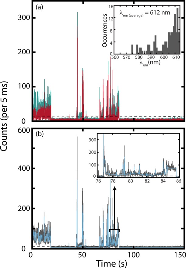
(a) PI trace for a single NR molecule in PVDF. Displayed are reflected (teal, λem > 600) and transmitted (red, 500 > λem > 600) intensities. The inset presents the histogram of emission wavelengths observed from the deconvolved emissive segments with an average emission wavelength of 612 nm. (b) PI trace produced by summing the intensities from the reflected and transmitted channels (solid gray line), emissive threshold (dotted black line), and intensity states identified using the BDIC algorithm (light blue line). The inset presents a 10 s section of the trace enlarged to illustrate the BDIC algorithm’s sensitivity to emissive intensity changes.
Table 2. Data Summary after Categorizinga Based on the BDIC Algorithm.
| wavelength range (nm) | range of ε | median ε | category name |
|---|---|---|---|
| 501–560 | ∼2.0–2.8 | 2.2 | ε1 |
| 560–571 | 2.8–3.2 | 3.0 | |
| 571–578 | 3.2–3.6 | 3.4 | ε2 |
| 578–587 | 3.6–4.2 | 3.8 | |
| 587–596 | 4.2–5.7 | 4.8 | ε3 |
| 596–607 | 5.7–28 | 13 | ε4 |
| 607–616 | 28–58 | 44 | ε5 |
| 616–623 | 58–80 | 74 |
Each category contains 100 molecules.
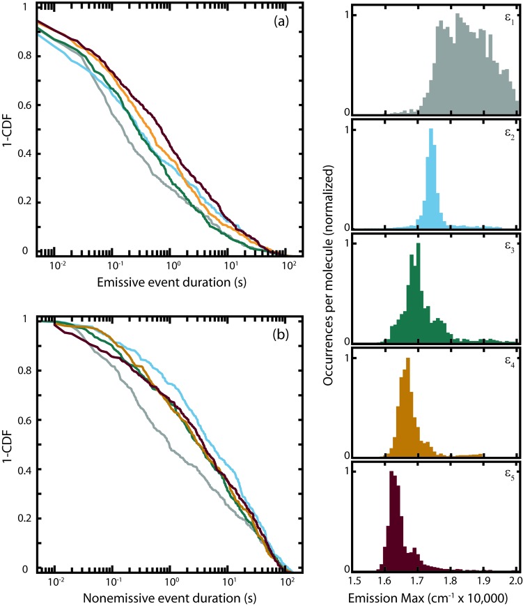
Histograms of calculated emission energies for five selected dielectric categories (Table 2) are shown in the right-hand column of Figure 3. This figure illustrates that the emissive segments identified by the BDIC algorithm are broadly distributed in terms of emissive energies, even for categories with a narrow range of average dielectric constants. CDFs for the emissive and nonemissive intervals are also provided in Figure 3. The motivation for comparing CDFs is the ability to gain mechanistic information without assuming a parametric form for the underlying PDFs. Attempts to fit the CDFs to power-law and log-normal distributions were made, but the fits were poor. We have yet to confirm an appropriate parametric form for these data. We note, however, that log–log representations of the CDFs demonstrate significant curvature across 4 decades in time, confirming that the underlying PDFs are not power-law.14−16 The differing shapes of the emissive and the nonemissive event CDFs indicate that the underlying PDFs are different. This can likely be attributed to different mechanisms for dark-state formation and decay. Additionally, we see that both the emissive and nonemissive event distributions have significant probabilities at large duration times, with ∼10% of the nonemissive events greater than 50 seconds in duration. Figure 3a demonstrates that the emissive event durations continuously increase with increasing ε, while Figure 3b shows an initial increase in nonemissive event durations and a subsequent decrease as ε increases.
Figure 3.
Complementary CDFs for the emissive (a) and nonemissive events (b) of single NR molecules in PVDF for the selected ε categories defined in Table 2. Color code: ε1 (gray), ε2 (cyan), ε3 (teal), ε4 (orange/brown), and ε5 (dark red). The right panel contains histograms of the emission energy for the deconvolved emissive segments for each ε category. The average number of emissive segments is 44 ± 11 per molecule.
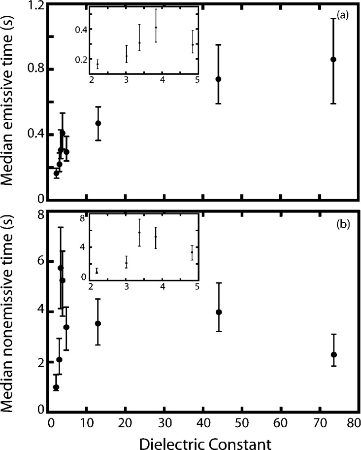
To explore the relationship between event durations and ε, the median event times were calculated and plotted versus ε for all eight dielectric categories (Table 2), as shown in Figure 4. The median is a better measure of the central tendency than the mean in heavy-tailed distributions as it is insensitive to outliers. The median event duration corresponds to the time at which the CDF is equal to 0.5 (see eq 2). The median emissive event durations demonstrate a 5-fold increase over the range of ε observed here, with most of the increase occurring between ε = 2 and 4. The nonemissive event durations demonstrate a different trend, with the median event duration initially increasing with ε until 3.4, after which a decrease in the median is observed as ε continues to increase. The PI results presented here demonstrate a clear relationship between a simple measure of the central tendency in the raw emissive and nonemissive event distributions and ε.
Figure 4.
Median emissive (a) and nonemissive (b) event durations versus the average dielectric constant for each ε category defined in Table 2. Error bars correspond to the 95% confidence interval, calculated from 10 000 bootstrap samples. Insets in both (a) and (b) provide an expanded view of the data from 2 < ε < 5.
Discussion
The connection between PI and the local dielectric environment poses a significant issue in interpreting the pattern of emissive intensity exhibited by SMs. Establishing the relationship between the rates of dark-state formation and decay and the polarity of the surrounding environment provides unique insights into potential mechanisms for PI. The results presented here represent a simple, unbiased treatment of SM data that establishes that the PI exhibited by NR is indeed sensitive to the local dielectric environments provided by PVDF.
In our analysis, three easily implemented statistical tools are used to decompose the PI data into emissive and nonemissive durations and to present the resulting distributions graphically. First, the PI data were parsed using the BDIC algorithm to identify statistically significant changes in emissive intensity using a single adjustable parameter to tune the sensitivity of the algorithm.20 Using the relationship between emissive energy and ε (Figure 1), we are able to determine the average local dielectric constant of each individual NR molecule. Second, generation of the CDFs provides the ability to analyze changes in the distributions without having to assume a parametric form while also allowing for a simple investigation into the functional form of the underlying PDF. Finally, by recognizing that the emissive and nonemissive event duration distributions are heavy-tailed, we are able to employ the median as a simple measure of the distribution’s central tendency, which allows us to directly monitor the impact of ε on PI.
The NR/PVDF guest–host pair provides the opportunity to study the effect of the local dielectric environment on PI without altering the chemical composition of the guest or host. This is possible as PVDF films expressed in the ferroelectric phase consist of a mixture of nonpolar (α - TGTG′ configuration) and polar (β - TTTT configuration) domains corresponding to a variation in the dielectric constant.22 Meanwhile, the solvatochromic properties of NR report directly on the different dielectric domains and their stability with time. This is illustrated in the right-hand column of Figure 3. Spectral diffusion within the dielectric categories is evident by the broad tailing distributions of the emissive segment energies. This indicates that the polarity of the surrounding environment fluctuates, consistent with other observations of spectral diffusion in soft and complex materials.2,23
Qualitatively, the CDFs for NR as a function of ε (Figure 3) are markedly different for emissive versus nonemissive events. This observation suggests that the mechanisms for dark-state formation and decay are not the same. This result is further confirmed through the observation of a variation in median emissive and nonemissive event durations with ε (Figure 4). Finally, the nonemissive durations are much longer on average than the emissive durations, consistent with a larger driving force for dark-state formation relative to decay of this state.
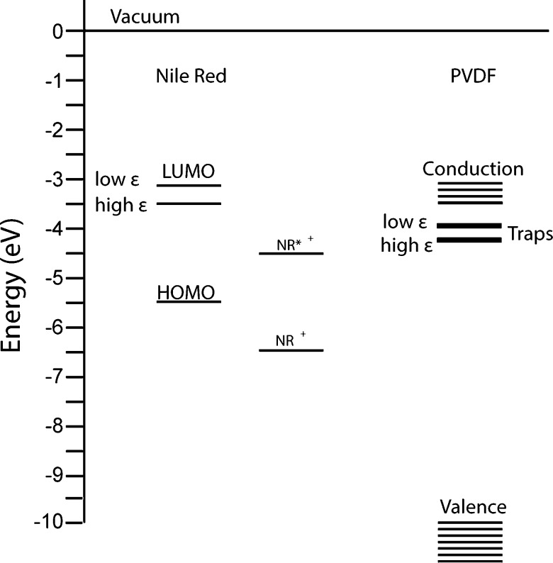
The prevailing hypothesis for dark-state formation in organic guest–host systems is photoinduced electron transfer. To test the viability of this hypothesis for NR/PVDF, we first consider the physical properties of this guest–host pair. PVDF is aprotic and has been classified as an n-type semiconducting polymer, with electron trap energies distributed between −0.46 and −0.73 eV below the conduction band. The ferroelectric properties of PVDF are highly dependent on the movement of electrons, with filling of the electron traps proposed to be part of the mechanism for domain alignment.24 NR has been extensively used as a solvent polarity probe, with the photoexcited state of NR depending on the solvent.25 For instance, in polar aprotic solvents, photoexcited NR has a planar geometry and is classified as a locally excited state with a change of ∼5 D in dipole moment.13 In polar protic solvents, twisted intramolecular charge transfer can occur between the donor amine and phenoxazinone moiety, which quenches fluorescence.25 Flash photolysis studies of NR in acetonitrile have confirmed the formation of a radical cation with absorption at 680 nm.26 This observation is consistent with an oxidation potential of NR in acetonitrile of +0.95 V.27 Further electrochemical and physical parameters for NR and PVDF are presented in Table 3. These parameters suggest photoinduced electron transfer between electron donor NR and acceptor PVDF as a possible mechanism for PI. NR is expected to be the donor due to the favorable formation of the radical cation and the poor capacity for aprotic solvents to stabilize anion formation. A corresponding energy level diagram derived using the parameters reported in Table 3 is presented in Figure 5. This figure illustrates that PVDF electron traps are in energetic proximity to the LUMO of NR, allowing for photoinduced electron transfer between NR and these traps.
Table 3. Electrochemical and Physical Parameters for NR and PVDF.
| parameter | NR | parameter | PVDF |
|---|---|---|---|
| aE0(D+/D)(acetonitrile)a | –0.95 V | binding energye | –10 eV (from vacuum) |
| aE0(D/D−)(acetonitrile)a | –2.087 V | band gapf | 6.5 eV |
| HOMOb | –5.5 eV | measured trap distributiong | –0.46 to −0.73 eV (from conduction) |
| LUMOb | –3.2 to –3.5 eV | index of refraction, ηh | 1.42 |
| NR+ band gapc | 1.82 eV | domain sizei | 12 Å |
| radiid | 4.08 Å |
Figure 5.
Energy level diagram for NR, NR+, PVDF, and PVDF traps. In the proposed photoinduced electron-transfer model, electron transfer from NR to traps generates NR+, and the transferred electron “fills” the trap, promoting population of the conduction band. Electrochemical and physical parameters used to construct this diagram are listed in Table 3.
A simple model for NR/PVDF photoinduced electron transfer can be constructed using the semiclassical Marcus expression for the electron-transfer rate (ket)34,35
| 4a |
| 4b |
| 4c |
In the above expressions, κel represents the electronic coupling energy between the reactant and product states, λ is the reorganization energy, ΔGel is the free energy, kB is the Boltzmann constant, and T is the temperature. The electron-transfer rate has two contributing parts, the energetics of the reaction corresponding to the reorganization energy and the free energy for the reaction and the coupling between states (κel). The electronic coupling is modeled as shown in eq 4c, where dcc is the distance between reaction centers of the donor and acceptor and β describes the fall off of the orbital interaction between the donor and acceptor with distance. We approximated the distance to the nearest trap to be on the order of the PVDF domain size, which ranges from 10 to 40 nm.33 Using a typical value of β = 0.85 Å–1, we estimate Hel to be ∼1 × 10⁻⁶ eV.34
The reorganization energy in eq 4a represents the sum of the internal reorganization energy (structural changes within the donor and acceptor) and the “outer-shell” reorganization energy (solvent reorganization). Under the assumption that the NR cation ground-state structure is similar to that of neutral NR, the internal reorganization energy will be small, and solvent reorganization will dominate the total reorganization energy. The solvent reorganization energy is modeled using34
| 5 |
In the above expression, rD/A are the radii of the donor and acceptor species, respectively, η is the index of refraction of the solvent, e is electronic charge, ϵ0 is the permittivity of free space, and ε is the dielectric constant of the solvent.
With regards to the driving force for the reaction, the oxidation potential of the donor (ED+/D0) is known; however, to account for the fact that we are considering photoinduced electron transfer, the free energy is adjusted by the energy difference between the equilibrated neutral excited state and the neutral ground state (ΔE00) of the donor. Additionally, to account for the oxidation potential of NR being measured in acetonitrile (ε = 37), we include a solvent-separated ion pair energy term (an approximation commonly attributed to Rehm and Weller) in determining the reaction driving force. Finally, we include the energy released upon Coulombic attraction of the two ions, resulting in the full expression for ΔGel34
| 6 |
The solvent dependence of ΔE00 has been measured previously and is given by eq 1.18 While most of the parameters needed to evaluate eq 6 have been measured, the final quantity needed is the reduction potential of the PVDF electron traps (E0trap/trap–). Previous single emitter studies found that the power-law exponent describing the nonemissive event durations decreased with an increase in environment polarity (achieved by changing the chemical composition of the host), consistent with increased stabilization of the charge-separated state in more polar environments.15,16 This stabilization energy is proportional to ∼1 – (1/ε). Building on this earlier study, the reduction potentials of the traps are modeled using the field stabilization energy and the initial trap potential (Etrap)16
| 7 |
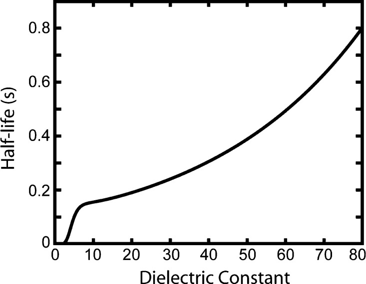
In the above expression, ΔE(1 – ε–1) can be thought of as representing the width of the trap distributions, measured to be ∼0.3 V, over the range of observed dielectric constants. Correspondingly, Etrap can be viewed as the trap depth. For our model, we estimate the initial trap reduction potential to be Etrap = −2.35 eV, consistent with resistance to filling an electron trap. Using Etrap as the only adjustable parameter, the median emissive events were modeled using the half-life as a proxy for the median emissive event duration (half-life = log(2)/ket). The results of this modeling are shown in Figure 6. The increase in half-life with dielectric constant is in qualitative agreement with the increase in median emissive event durations, as shown in Figure 4. Specifically, the model predicts a rapid increase in half-life as ε increases from 2 to 5 and then a slower increase with further increase in ε. These results show that by using a basic approximation for the free energy that considers the solvent effects on the oxidation and reduction potentials of the donor and acceptor, the energetics of the NR excited state, and the PVDF dynamic trap energies, the evolution in median emissive event durations can be reproduced.
Figure 6.
Result of modeling the photoinduced electron transfer from NR to PVDF. The half-life serves as a proxy for the median emissive event durations. The observed trend for half-life with dielectric constant is consistent with median emissive event durations shown in Figure 4a.
Finally, we calculate the activation energy (ΔG*) for the electron transfer using34
| 8 |
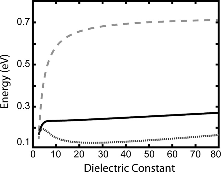
The variation in λ, ΔGel, and ΔG* with dielectric constant from our model is shown in Figure 7. Figure 7 demonstrates that λ > ΔGel at all dielectric constants, indicating that electron transfer occurs in the normal Marcus regime. The activation barrier increases with dielectric constant, which gives rise to a decrease in ket with increasing ε. In addition, ΔGel > 0, indicating that the reaction is “uphill” in energy. This is consistent with the observation of a larger number of nonblinking molecules with an increase in ε (Table 1), as well as a narrowing in the emissive energy histograms with increasing ε (Figure 3).
Figure 7.
Reorganization energy λ (light gray dashed line), free energy ΔGel (dark gray dotted line), and activation energy ΔG* (black solid line) versus the dielectric constant. Energies were calculated using eqs 5, 6, and 8, respectively. These three parameters define the relative position and crossings of the reactants and product potentials for the electron transfer.
While the emissive event durations can be modeled using a photoinduced electron-transfer mechanism, the nonemissive events are not as simply described by a back-electron-transfer model. While the initial increase in nonemissive event durations is consistent with the hypothesis that an increase in ε provides for stabilization of the charge-separated state (and correspondingly longer nonemissive event durations as others have suggested14−16), the subsequent decrease in nonemissive event durations as ε continues to increase is more difficult to explain. It could be that the back electron transfer occurs through another mechanism (e.g., tunneling) as the comparison of the emissive and nonemissive event CDFs suggests. Differentiation between these electron-transfer mechanisms should be evidenced by different PDFs describing emissive and nonemissive event durations. The challenge is to directly determine the PDFs from the PI data without a priori assumptions of the PDF functional form, a new PI analysis tool on which we will report shortly.
Conclusion
We have measured the variation in PI with the local dielectric environment for NR in PVDF. By employing the NR/PVDF guest/host system, a direct correlation between PI and ε can be determined while maintaining the chemical composition of both the guest and host. Through comparative analysis of the CDFs and the median event durations, we find that the emissive event durations continually increase with ε. In contrast, the NR nonemissive event durations initially increase with ε but then gradually decrease with a further increase in ε. We were able to demonstrate that the emissive event results can be rationalized using a photoinduced electron-transfer model for PI. In addition, an increase in NR photostability with an increase in ε was observed, suggesting that the dielectric constant plays an important role in defining the molecular photostability in PVDF.
Acknowledgments
This work was supported by the National Science Foundation (DMR-1005819 for materials development and CHE-1404674 for analysis). Part of this work was conducted at the University of Washington NanoTech User Facility, a member of the NSF National Nanotechnology Infrastructure Network (NNIN). E.A.R. supported by the UW NIEHS-sponsored Biostatistics, Epidemiologic and Bioinformatic Training in Environmental Health (BEBTEH) Training Grant (T32ES015459).
Supporting Information Available
A more detailed description of the Bayesian detection of intensity changes (BDIC) method employed in this study is available. This material is available free of charge via the Internet at http://pubs.acs.org.
The authors declare no competing financial interest.
Funding Statement
National Institutes of Health, United States
Supplementary Material
References
- Orrit M. Chemical and Physical Aspects of Charge Transfer in the Fluorescence Intermittency of Single Molecules and Quantum Dots. Photochem. Photobiol. Sci. 2010, 9, 637–642. [DOI] [PubMed] [Google Scholar]
- Riley E. A.; Hess C. M.; Reid P. J. Photoluminescence Intermittency from Single Quantum Dots to Organic Molecules: Emerging Themes. Int. J. Mol. Sci. 2012, 13, 12487–12518. [DOI] [PMC free article] [PubMed] [Google Scholar]
- Wustholz K. L.; Sluss D. R. B.; Kahr B.; Reid P. J. Applications of Single-Molecule Microscopy to Problems in Dyed Composite Materials. Int. Rev. Phys. Chem. 2008, 27, 167–200. [Google Scholar]
- Kulzer F.; Xia T.; Orrit M. Single Molecules as Optical Nanoprobes for Soft and Complex Matter. Angew. Chem., Int. Ed. 2010, 49, 854–866. [DOI] [PubMed] [Google Scholar]
- Clifford J. N.; Bell T. D. M.; Tinnefeld P.; Heilemann M.; Melnikov S. M.; Hotta J.; Sliwa M.; Dedecker P.; Sauer M.; Hofkens J. Fluorescence of Single Molecules in Polymer Films: Sensitivity of Blinking to Local Environment. J. Phys. Chem. B 2007, 111, 6987–6991. [DOI] [PubMed] [Google Scholar]
- Kuno M.; Fromm D. P.; Hamann H. F.; Gallagher A.; Nesbitt D. J. Nonexponential “Blinking” Kinetics of Single Cdse Quantum Dots: A Universal Power Law Behavior. J. Chem. Phys. 2000, 112, 3117–3120. [Google Scholar]
- Cichos F.; von Borczyskowski C.; Orrit M. Power-Law Intermittency of Single Emitters. Curr. Opin. Colloid Interface Sci. 2007, 12, 272–284. [Google Scholar]
- Frantsuzov P.; Kuno M.; Janko B.; Marcus R. A. Universal Emission Intermittency in Quantum Dots, Nanorods and Nanowires. Nat. Phys. 2008, 4, 519–522. [Google Scholar]
- Riley E. A.; Hess C. M.; Whitham P. J.; Reid P. J. Beyond Power Laws: A New Approach for Analyzing Single Molecule Photoluminescence Intermittency. J. Chem. Phys. 2012, 136, 184508. [DOI] [PubMed] [Google Scholar]
- Schmidt R.; Krasselt C.; Goehler C.; von Borczyskowski C. The Fluorescence Intermittency for Quantum Dots Is Not Power-Law Distributed: A Luminescence Intensity Resolved Approach. ACS Nano 2014, 8, 3506–3521. [DOI] [PubMed] [Google Scholar]
- Riley E. A.; Hess C. M.; Pioquinto J. R. L.; Kaminsky W.; Kahr B.; Reid P. J. Proton Transfer and Photoluminescence Intermittency of Single Emitters in Dyed Crystals. J. Phys. Chem. B 2012, 117, 4313–4324. [DOI] [PubMed] [Google Scholar]
- Verberk R.; Orrit M. Photon Statistics in the Fluorescence of Single Molecules and Nanocrystals: Correlation Functions Versus Distributions of On- and Off-Times. J. Chem. Phys. 2003, 119, 2214–2222. [Google Scholar]
- Hou Y. W.; Bardo A. M.; Martinez C.; Higgins D. A. Characterization of Molecular Scale Environments in Polymer Films by Single Molecule Spectroscopy. J. Phys. Chem. B 2000, 104, 212–219. [Google Scholar]
- Schuster J.; Cichos F.; von Borczyskowski C. Influence of Self-Trapped States on the Fluorescence Intermittency of Single Molecules. Appl. Phys. Lett. 2005, 87, 051915. [Google Scholar]
- Issac A.; von Borczyskowski C.; Cichos F. Correlation between Photoluminescence Intermittency of Cdse Quantum Dots and Self-Trapped States in Dielectric Media. Phys. Rev. B 2005, 71, 161302. [Google Scholar]
- Issac A.; Krasselt C.; Cichos F.; von Borczyskowski C. Influence of the Dielectric Environment on the Photoluminescence Intermittency of Cdse Quantum Dots. ChemPhysChem 2012, 13, 3223–3230. [DOI] [PubMed] [Google Scholar]
- Brandrup J.; Immergut E. H., Grulke Eric A.. Polymer Handbook; Wiley: New York, 1999. [Google Scholar]
- Hess C. M.; Riley E. A.; Palos-Chávez J.; Reid P. J. Measuring the Spatial Distribution of Dielectric Constants in Polymers through Quasi-Single Molecule Microscopy. J. Phys. Chem. B 2013, 117, 7106–7112. [DOI] [PMC free article] [PubMed] [Google Scholar]
- Satapathy S.; Pawar S.; Gupta P. K.; Varma K. B. R. Effect of Annealing on Phase Transition in Poly(vinylidene fluoride) Films Prepared Using Polar Solvent. Bull. Mater. Sci. 2011, 34, 727–733. [Google Scholar]
- Ensign D. L.; Pande V. S. Bayesian Detection of Intensity Changes in Single Molecule and Molecular Dynamics Trajectories. J. Phys. Chem. B 2010, 114, 280–292. [DOI] [PubMed] [Google Scholar]
- Watkins L. P.; Yang H. Detection of Intensity Change Points in Time-Resolved Single-Molecule Measurements. J. Phys. Chem. B 2005, 109, 617–628. [DOI] [PubMed] [Google Scholar]
- Bassett D. C.Developments in Crystalline Polymers; Applied Science Publishers LTD: Essex, England, 1982; Vol. 1, p 279. [Google Scholar]
- Wustholz K. L.; Bott E. D.; Kahr B.; Reid P. J. Memory and Spectral Diffusion in Single-Molecule Emission. J. Phys. Chem. C 2008, 112, 7877–7885. [Google Scholar]
- Chand S.; Bhatheja R. C.; Sharma G. D.; Chandra S. Charge Trapping Levels in Vacuum-Evaporated Polyvinylidene Fluoride Films. Appl. Phys. Lett. 1994, 64, 2507–2508. [Google Scholar]
- Freidzon A. Y.; Safonov A. A.; Bagaturyants A. A.; Alfimov M. V. Solvatofluorochromism and Twisted Intramolecular Charge-Transfer State of the Nile Red Dye. Int. J. Quantum Chem. 2012, 112, 3059–3067. [Google Scholar]
- Anandan S.; Yoon M. Photoinduced Electron Transfer Studies of Nile Red in the Presence of TiO2 Colloidal Nanoparticles. Spectrochim. Acta, Part A 2004, 60, 885–888. [DOI] [PubMed] [Google Scholar]
- Miyata S., N H. S.. Organic Electroluminescent Materials and Devices; Gordon and Breach Science Publishers: Amsterdam, The Netherlands, 1997. [Google Scholar]
- Liu Y. X.; Summers M. A.; Scully S. R.; McGehee M. D. Resonance Energy Transfer from Organic Chromophores to Fullerene Molecules. J. Appl. Phys. 2006, 99, 093521. [Google Scholar]
- Andersson S. B. A Nonlinear Controller for Three-Dimensional Tracking of a Fluorescent Particle in a Confocal Microscope. Appl. Phys. B: Laser Opt. 2011, 104, 161–173. [Google Scholar]
- Mohanty J.; Pal H.; Sapre A. V. Excited Singlet (S–1)-State Interactions of Nile Red with Aromatic Amines. Photochem. Photobiol. 2003, 78, 153–158. [DOI] [PubMed] [Google Scholar]
- Bureau C.; Chong D. P.; Endo K.; Delhalle J.; Lecayon G.; LeMoel A. Recent Advances in the Practical and Accurate Calculation of Core and Valence XPS Spectra of Polymers: From Interpretation to Simulation?. Nucl. Instrum. Methods Phys. Res., Sect. B 1997, 131, 1–12. [Google Scholar]
- Duan C. G.; Mei W. N.; Hardy J. R.; Ducharme S.; Choi J. W.; Dowben P. A. Comparison of the Theoretical and Experimental Band Structure of Poly(vinylidene fluoride) Crystal. Europhys. Lett. 2003, 61, 81–87. [Google Scholar]
- Guan F.; Wang J.; Pan J.; Wang Q.; Zhu L. Effects of Polymorphism and Crystallite Size on Dipole Reorientation in Poly(vinylidene fluoride) and Its Random Copolymers. Macromolecules 2010, 43, 6739–6748. [Google Scholar]
- Kavarnos G. J.Fundamentals of Photoinduced Electron Transfer; VCH Publishers, Inc.: New York, 1993. [Google Scholar]
- Marcus R. A.; Sutin M. Electron Transfers in Chemistry and Biology. Biochimica et Biophysica Acta 1985, 811, 265–322. [Google Scholar]
Associated Data
This section collects any data citations, data availability statements, or supplementary materials included in this article.


