Abstract
A simple preparation of thermoreversible gelatin-based ferrogels in water provides a constant structure defined by the crosslinking degree for gelatin contents between 6 and 18 wt%. The possibility of varying magnetite nanoparticle concentration between 20 and 70 wt% is also reported. Simulation studies hint at the suitability of collagen to bind iron and hydroxide ions, suggesting that collagen acts as a nucleation seed to iron hydroxide aggregation, and thus the intergrowth of collagen and magnetite nanoparticles already at the precursor stage. The detailed structure of the individual ferrogel components is characterized by small-angle neutron scattering (SANS) using contrast matching. The magnetite structure characterization is supplemented by small-angle X-ray scattering and microscopy only visualizing magnetite. SANS shows an unchanged gelatin structure of average mesh size larger than the nanoparticles with respect to gel concentration while the magnetite nanoparticles size of around 10 nm seems to be limited by the gel mesh size. Swelling measurements underline that magnetite acts as additional crosslinker and therefore varying the magnetic and mechanical properties of the ferrogels. Overall, the simple and variable synthesis protocol, the cheap and easy accessibility of the components as well as the biocompatibility of the gelatin-based materials suggest them for a number of applications including actuators.
1 Introduction
Living organisms are able to produce highly sophisticated materials.1 Biominerals are organic-inorganic hybrid materials abundant in Nature.1 They are formed under highly controlled conditions,2 show complex morphologies and are very often hierarchically structured.3 On each hierarchical level, the optimum structure is realized3 and consequently, much improved physical properties are obtained. An amazing biomineral is the chiton tooth. These animals scratch algae from rocks, which requires that their teeth are very hard and wear resistant. In fact, chiton teeth show the highest hardness and stiffness among the known biominerals being for example three times harder than human tooth enamel.4 The teeth themselves are hardened by the inclusion of magnetite nanoparticles (15–20 nm) into a protein-polysaccharide gel matrix. The high nanoparticle content makes the hybrid material very hard and wear resistant even enabling to scratch corals and stones. Chiton teeth are not the only biomineral which is formed in a gel matrix as a template. Nacre, another biomineral known for its exceptional fracture toughness is also synthesized inside a gel, in this case a silk hydrogel.5 Such syntheses could be successfully mimicked resulting in inclusion of the hydrogel inside a single crystal,6 which caused an increased mechanical stability, just as found in biominerals.7
Results like this imply that mineralization of inorganic components inside an aqueous hydrogel is an advantageous strategy towards advanced hybrid materials synthesis. Even if the gels are not as highly mineralized as in case of Biominerals, they can exhibit interesting properties since the viscoelasticity of the hydrogel and the swelling behaviour can be combined. In addition, many hydrogels are biocompatible which is an issue in medical applications.8–10 Variation of the mineral content can change the counterplay between the two components in the hydrogel and thus the properties of the hybrid material. It is therefore not astonishing that a large number of studies on hydrogels filled with inorganic nanoparticles were reported including hydrogels filled with metal,11–13 semiconductor14,15 and magnetic nanoparticles.16–20
The properties of these gels can be adjusted over a large range by simple variation of the organic-inorganic content allowing their use in applications as diverse as catalysis,21–23 switchable electronics,24,25 tissue engineering,26,27 drug delivery,28–31 wastewater treatment,32–34 hyperthermia cancer therapy35,36 and soft actuators.37,38 However, the synthesis of biocompatible magnetic hydrogels with high and adjustable magnetite content was not yet reported. These are, moreover, especially interesting because they can be moulded into any shape, can be used for medical applications and can be addressed by external magnetic fields making them interesting for applications as actuators, switches etc. Here we report the synthesis of biocompatible and thermoreversible gelatin gels which are mineralized with magnetite. A large variation of the organic/inorganic ratio is possible, magnetite loads of up to 70 wt% can be realized, which influences the materials structure, as shown by small-angle neutron scattering (SANS) using contrast variation to reveal the details of the organic, as well as of the inorganic structure.
2 Results and Discussion
2.1 Gelatin Hydrogel
Gelatin, which is derived from partial hydrolysis of native collagen, can be considered as a polydisperse copolymer with a broad molar mass distribution. The gelatin Type B used in our experiments has a molar mass of approximately 25–50 kDa. Native collagen forms a triple helical structure which is stabilized by interchain hydrogen bonds.39 At temperatures above the gelation temperature (Tgel) gelatin forms a homogeneous solution in water, which transforms below Tgel and above the overlap concentration of ∼0.5 wt% (in H2O) to a thermoreversible physical gel.40 During the cooling process the gelatin undergoes conformational changes, the so called coil to helix transition. Most of the gelatin chains form a three-dimensional interconnected network of chains reverted back from a random coil to a triple-helical structure.39
The structure of a gelatin hydrogel at room temperature in D2O was determined by SANS. The scattering pattern plotted in Figure 1 were measured at classical SANS and USANS diffractometers delivering scattering at very small Q of the order 10−3 up to 3 nm−1. USANS instruments have to use optical devices such as refraction lenses or mirrors.41 There are two distinct Q-regimes which are well described by the solid line representing the best fit of the data using the two levels Beaucage expression.42 The Beaucage expression is given according to
| 1 |
representing a combination of Guinier's and Porod's laws describing the scattering at low and large Q, respectively. More quantitatively both approximations are valid for the parameter u = RgQ smaller or larger than 1, u representing the product of radius of gyration Rg and scattering vector Q (defined below). Guinier's law has the shape of a Gaussian function whereas for Q larger than 1/Rg (u>1) a power law according to  is often observed, which in case of α = 4 represents the famous Porod law of compact particles with a sharp surface.43
Figure 1.
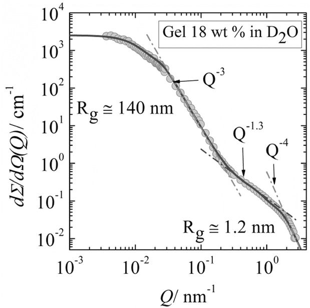
SANS macroscopic cross-section dΣ/dΩ versus scattering vector Q for 18 wt% gelatin in D2O (T = 20 °C). At low Q (< 0.02 nm−1) USANS data are also presented after rescaling. The solid line represents a fit of the two levels Beaucage equation.
For 18 wt% gelatin in D2O the contribution from large inhomogeneities are dominant in the low Q regime (Q < 0.2 nm−1) representing a two phase random medium of about Rg = 140 nm radius of gyration and a power law exponent of α = 3 in the intermediate Q regime between 0.02 and 0.2 nm−1. These data indicate the formation of large-scale gel networks of mass fractal characteristic and of about 350 nm diameter. The fractal characteristic was concluded from the α = 3 exponent and the diameter was evaluated from Rg, assuming a spherical shape.43 The second relevant Q-regime between 0.2 nm−1 and 1.5 nm−1 shows a power law exponent of ∼1.3 indicating the rod-like structure of gelatin triple helix bundles. The third relevant Q-regime beyond 1.5 nm−1 shows Q−4 Porod law behavior, valid for three dimensional compact structures thereby indicating a shorter helix axis of about d ∼ 1/(Q = 1.5 nm−1) = 0.7 nm. The length of the helix bundle is roughly estimated as L ∼ 4.1 nm from Rg ∼ 1.2 nm and d according to Rg2 = L2/12 + d2/8.43 Moreover, the transition between the two power law regimes at Qc of approximately 0.29 nm−1 allows us to estimate the average gelatin mesh size of 2π/Qc ∼ 22 nm. Furthermore, the amplitude of the Porod regime delivers the total surface area per unit volume of the gel according to P4 = 0.583 cm−1 nm−4 (P4 = 2π × N × S × Δρ2, N particle number density, S particle surface, and Δρ = 4.71×1010 cm−2 scattering contrast).43 For 18 wt% gelatin this value is calculated as N × S ∼ 4.2 × 105 cm−1 (∼31.6 m2/g). These parameters show that the gel of the present study is a good candidate for growing nanoparticles within the mesh of the biopolymers; the high porosity represents a good medium for the growth of nanoparticles without aggregation.
SANS data from solutions of varying gelatin concentration are shown in Figure S3a (see Supporting Information). The scattering below Q ∼ 0.1 nm−1 shows an accumulation of a network structure of similar size and number density proportional to gel concentration. In the intermediate Q-regime we observe a lowering of the power law exponent from ∼2 to ∼1 with increasing gel concentration. The trend to α = 1, i.e. scattering from rod like particles, indicates an enhanced amount of triple helix bundles, which is not accompanied by a significant change of average mesh size (Table S1). In conclusion, the choice of appropriate gelatin concentration will achieve both high efficiency for ion transport for optimal iron mineralization as well as high mechanical strength. The latter parameter is known to increase with the amount of gelatin.
2.2 Ferrogel Synthesis
Magnetic field-sensitive gels are called ferrogels. They can be synthesized through various procedures such as blending, in situ co-precipitation or grafting method.44 Here, we report an in situ mineralization protocol designed for the preparation of ferrogels consisting of biodegradable polymer gelatin and magnetic iron oxide nanoparticles. A three-step process was applied as schematically represented in Figure 2. In a first step, gelatin hydrogels were prepared at different biopolymer concentrations, ranging from 6 to 18 wt% to allow for different mesh sizes in the gelatin gels through concentration dependent variation of the crosslinking degree. These hydrogels were soaked in a solution of FeII (0.1 mol L−1) and FeIII (0.2 mol L−1) ions with a molar ratio of ferrous to ferric ions of 1:2 until they reached the swelling equilibrium. In a third step magnetite was formed inside the gelatin network after immersing the gel into a NaOH (0.1 mol L−1) solution, which did not affect the gel properties. The porous polymer network structure of the hydrogel in combination with the carbonyl, amine and anionic groups of the gelatin molecules binds the metal cations45 (see Section 2.7) and thereby acts as a template for co-precipitation of magnetic nanoparticles according to the following reaction:
| 2 |
Figure 2.
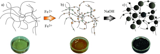
Schematic representation of the ferrogel synthesis. a) Unloaded gelatin hydrogel, b) hydrogel loaded with ferrous and ferric ions, and c) magnetic nanoparticles distributed inside the hydrogel after in situ co-precipitation with NaOH.
The loading of iron ions into the gelatin hydrogel can be followed visually by a change of color from white (native hydrogel) to bright orange (Figure 2). The intensity of the color also provides a measure of the concentration of iron present in the gel matrix. Indeed, after several washing steps with water, the iron loaded gel does not change its color, indicating strong binding of the iron ions to the gelatin network. When sodium hydroxide is added to the iron-containing hydrogels the color changed rapidly from bright orange to black denoting the formation of magnetite inside the gelatin matrix. We could repeat the three-step protocol several times in order to control the mineral content. Similar approaches were reported46,47 for example Breulmann et al.16 synthesized magnetite nanoparticles in situ in a polystyrene-polyacrylate copolymer gel to form an inorganic-organic nanocomposite with magnetic and elastic properties. By contrast Reddy et al.48 precipitated magnetite within a polyacrylamide/gelatin hydrogel matrix in order to produce a biocompatible magnetic hybrid material.
The final amount of magnetite nanoparticles inside the biopolymer matrix was determined by thermogravimetric analyses (TGA) in an oxygen atmosphere. From the thermograms, onset temperature and completion of degradation temperature can be identified (see Figure S2 in the Supporting Information). All dry ferrogels investigated show two stages of weight loss. First, there is a minor change in mass between 80 and 180 °C due to removal of moisture from the sample. In a second stage (200–400 °C), the gelatin part of the biopolymer is completely decomposed. Thus, the remaining mass represents the amount of iron oxide originally distributed in the ferrogel. In comparison, for pure magnetite there was no weight loss noted in the interval of 200–800 °C. Our experiments show that after one reaction cycle of magnetite incorporation, mineral contents of ca. 20–30 wt% can be realized. Higher nanoparticle loads of up to 70 wt% are also possible, but require repetition of the reaction cycles with repeated Fe-ion loading and mineralization cycles. In comparison to previous investigations which reported magnetite amounts of up to 30 wt%,49 the mineral loading in the present study is significantly higher.
2.3 Crystal Morphology and Size
Transmission electron microscopy (TEM) images Figure 3) reveal that the applied in situ co-precipitation method led to the formation of magnetic nanoparticles with a mean diameter of about 10 ± 5.3 nm inside a 10 wt% gel matrix, all synthesized nanoparticles showed similar mean diameters irrespectively of the gelatin concentration. These particles show spherical morphology and a well-developed crystallinity, which is supported by selected-area electron diffraction (SAED) and X-ray diffraction (XRD) analysis (see Figure S1 in the Supporting Information). Notably, the magnetic nanoparticles do not show any uncontrolled aggregation which might be due to colloidal stabilization by gelatin. The arrangement of the crystallites along the gelatin triple helices (see Section 2.7) can be attributed to the strong protein ion interaction which leads to the alignment along the biopolymer fibers as shown in Figure 3. Gelatin Type B shows an isoelectric point of 4.7–5.2,45 whereas the iron oxide particles in water have a point of zero charge around 7.50 The measured pH value of the ferrogels after synthesis is around 6, which provides an attractive interaction between the positively charged nanoparticles and the negatively charged gelatin molecules. Figure 3 shows mirco-cuts of an embedded ferrogel sample (10 wt% gelatin after 6 reaction cycles), where a homogenous distribution of the colloidal stable magnetic nanoparticles inside the hydrogel is evident. Interestingly, the TEM data suggest the presence of two distinct particle populations, that is, ca. 10 nm crystalline nanoparticles coexist with small clusters in the size range of 4.0 ± 1.1 nm. Moreover, TEM observations of ferrogel samples after different numbers of reaction cycles show that repetition of the precipitation procedure does not influence the size or shape of the nanoparticles but just their number which is in agreement with earlier findings.16 The SAED pattern in Figure 3b exhibits diffraction peaks that can be indexed to both magnetite (Fe3O4) and maghemite (Fe2O3). Due to the similar diffraction patterns of these two magnetic mineral phases, it is not possible to unequivocally distinguish between their crystal structures in ED and XRD analyses. The results obtained by SAED are in agreement with the data collected by XRD. All synthesized hybrid materials display an XRD pattern typical for magnetite or maghemite, with no other impurities being detected. Systematic HR-TEM studies of iron oxide nanoparticles showed lattice spaces attributed to magnetite. The HR-TEM image (Figure 3a) shows spacings of 0.48 and 0.24 nm, which correspond to the (111) and (222) plane of magnetite, respectively. This implies that all collected XRD and ED data represent the inverse spinel mineral magnetite.
Figure 3.
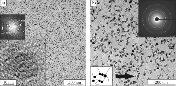
TEM images of a) and b) ultramicro-cuts of an embedded ferrogel at 10 wt% gelatin concentration after 6 reaction cycles (RC) at different magnifications.
Morphological aspects of the dried gelatin hydrogels and the magnetic hybrid gels were further investigated by scanning electron microscopy (SEM). In this study, SEM was used to visualize differences in the gelatin network structure before and after magnetite loading. The prepared samples were dried at room temperature, which leads to a decrease in the sample volume and results in the formation of a contracted porous hybrid material. Cross-sections of dried gelatin and ferrogel samples can be seen in Figure 4. Comparing the pore structure with and without loaded magnetite suggests that the dried ferrogel samples exhibit smaller pore sizes and therefore a denser gel network. Figure 4b clearly illustrates the homogenous distribution of aggregated magnetite nanoparticles inside the ferrogel at the micrometer scale.
Figure 4.
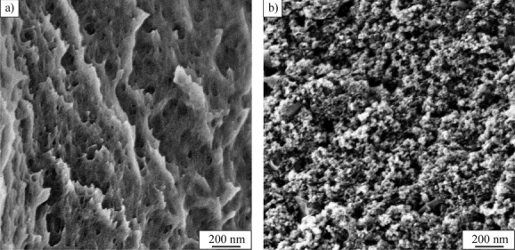
Morphology and pore size of two dried hydrogels a) without and b) with magnetite incorporated.
2.4 Small Angle Scattering Study on the Hybrid Structure
In order to further clarify the structure of the gelatin–nanoparticle hybrid material, we performed SANS contrast variation experiments, which allowed to independently explore the inorganic nanoparticle structure as well as the gelatin gel network. Contrast variation SANS experiments became a standard method as pointed out and applied also in cognate disciplines such as biomineralization.51,52] Figure 5 displays two SANS scattering patterns of a ferrogel dissolved in pure D2O and in an aqueous mixture of 28 vol% D2O matching the scattering of magnetite and gelatin, respectively. In D2O, when gelatin is the only visible part, the scattering at small Q (Q < 0.2 nm−1) delivers a radius of gyration of about 110 nm which is of similar size (140 nm) as found for pure gelatin (Figure 1), suggesting scattering from gelatin and the absence of magnetite aggregation as it was also concluded from TEM. The large Q-regime shows stronger scattering than pure gelatin suggesting an increased triple-helix to coil ratio; the fitting shows a slight increase of Rg to 1.7 nm due to a larger amount of triple-helix structure.
Figure 5.
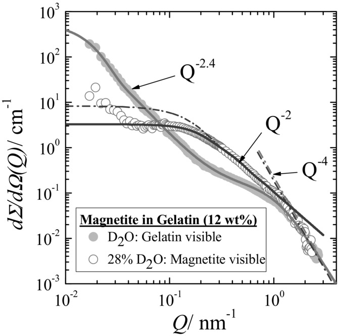
SANS scattering pattern of the ferrogel in pure D2O and in a mixed D2O/H2O solvent of 28 vol% D2O and 72 vol% H2O. The solid lines represent the fitting of the Beaucage expression. The form factor of the magnetite is plotted as dashed dotted line.
The open circles in Figure 5 represent the scattering of the ferrogel in a 28 vol% D2O aqueous solution, which matches the gelatin scattering and visualizes the magnetite nanoparticles.53 There is weakly enhanced scattering in the small Q-range, which might be caused from non-perfect matching of gelatin or of very small amount of aggregated magnetite. The scattering in the intermediate Q-range is caused from individual nanoparticles of Rg = 10.4 ± 1.2 nm showing a Q−2 power law at intermediate Q which might indicate a larger size distribution. The diameter D of the magnetite particles can be estimated as D ∼ 27 ± 4 nm (Rg = D/2.58).43 This value is larger than obtained from TEM (diameter D = 10 nm), but of similar size as the mesh of the biopolymer gel (∼22 nm). The bigger particle diameter obtained by SANS could also result from the dense and chain-like packing of the nanoparticles partially observed along the triple helices between the crosslinking points. This means, that magnetite does not destroy the fractal structure of the ferrogel representing a three-dimensional interconnected network as also seen from the Q−2.4 power law of the “gelatin” scattering in Figure 5. Moreover, the results suggest that the gel matrix determines the size of the magnetite as it prevents the nanoparticles from further growth as well as from aggregation. TEM also observed smaller particles of 4 ± 1.1 nm diameter which is consistent with the transition to Porod behavior at QP = 1.4 nm−1 (D ∼ 2π/Qp = 4.4 nm).
The scattering of magnetite in Figure 5. shows some slight correlation of the particles which means the observation of a structure factor. The effect of spatial correlation of the magnetite particles becomes more transparent from the X-ray scattering experiments discussed in Figure 6. Figure 5 showing scattering patterns of 12 and 18 wt% ferrogels in wet and dry conditions. In X-ray scattering the contribution of the gel matrix is less than 5%, which means that the scattering is dominated by magnetite.
Figure 6.
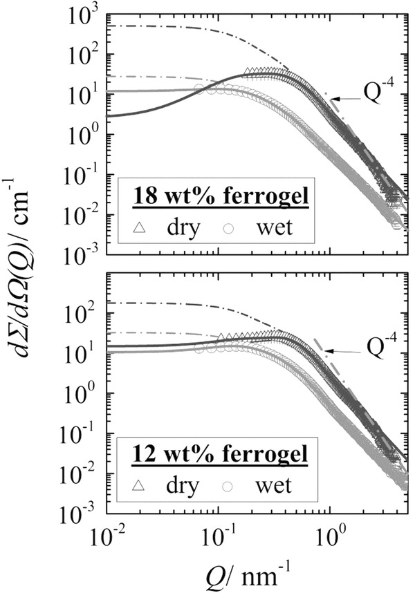
SAXS intensity dΣ/dΩ(Q) versus scattering vector Q for a 18 and 12 wt% wet and dry ferrogel. In all cases the structure factor S(Q) was not negligible. Therefore, the data were fitted with the product of Equation S2 in the SI (structure factor) and the Beaucage equation (form factor) as shown by the solid lines. The dashed dotted lines represent the form factor of the particles.
The experimental data are described by Equation 3 representing a product of form factor of
| 3 |
with dΣB/dΩ(Q) and the structure factor S(Q) describing the correlation between the magnetite particles. dΣB/dΩ(Q) expressed by Equation 1, was also applied for the other SANS data. The fits depicted as solid lines describe the data sufficiently well as already demonstrated for the SANS data in Figure 5. The dashed dotted lines represent the form factor (dΣB/dΩ(Q)) of magnetite. The expression of the structure factor is given in Equation S3 (SI) as derived on basis of the hard sphere potential in Equation S2.
The parameters of this analysis are compiled in Table S2 and S3 for small-angle X-ray scattering (SAXS) and SANS, respectively. For the 18 wt% wet ferrogel we find particles of 10 nm from SAXS and SANS whereas a slightly larger negative exponent of 2.73 (instead of 2) for the SAXS data. In contrast to SANS no transition to Q−4 was observed for these solutions from SAXS. The 12 wt% wet ferrogel shows a smaller Rg of 8.7 nm and Q−3 power law at larger Q. The dry samples show much stronger scattering and correlation between magnetite because of their enhanced dense packing. At intermediate Q one has Q−3 which at Q = 2.3 nm−1 transforms to Q−4 power law. The Q−3 behavior suggests a composite mass fractal structure of magnetite. The correlation peak of the dry samples at Qm ∼ 0.4 nm−1 provides an average distance of the scattering particles of Λ ∼ 10 nm54 (Guinier; Λ = 1.23π/Qm), which is almost the same as Rg of the particles. This means that in the dry ferrogel the nano-particles are closely packed. In summary the SANS and SAXS data suggest that the gelatin content has no significant influence on the size of the nanoparticles, i.e. the gel matrix of different concentrations has similar average mesh size which is of similar size as the nanoparticles. Parameters are shown in Table S1, S2, and S3.
2.5 Magnetic Measurements
The magnetic properties of the composite materials were characterized by using a superconducting quantum interference device (SQUID) magnetometer. Figure 7a shows the magnetization (M) of a representative dried ferrogel sample (10 wt% gelatin in the hydrated gelified state, 60.4 wt.-% mineral content in the dried ferrogel state) as a function of the applied field (H) at 293 K and 2 K. At T = 2 K the magnetization curve shows typical ferrimagnetic hysteresis due to magnetic anisotropy. At 293 K there is no hysteresis observed, which is typical for superparamagnetic materials,55 and consistent with the small size of the nanoparticles. The field-cooled (FC) and zero-field-cooled (ZFC) magnetizations of the magnetite-gelatin composites were also measured (Figure 7b). The maximum of the ZFC curve corresponds to the blocking temperature (TB).56 Values obtained for TB as well as for the saturation magnetization (Ms) at 5000 Oe are listed in Table 1 for several representative samples. The studies show a blocking temperature of around 120 K which also confirms the superparamagnetic behavior of the nanoparticles. The higher TB found for the ferrogel at a lower gelatin concentration (cf. Table 1) might be due to stronger dipolar interactions and dense particle packing in the dry ferrogel state. As can be seen in Table 1 the saturation magnetization (Ms) of the composite materials is lower than that of bulk magnetite (92 emu/g) as well as maghemite (56 emu/g).57 This effect has been observed in many previous studies, and it was proposed that with decreasing particle size, the growing degree of spin disorder at the surface causes the decrease in Ms.58 It has also been reported that defects on the particle surface can influence the magnetic properties.58 The obtained magnetic measurement data show the phenomena of superparamagnetism for the designed composite materials, the same result is also observed for magnetite nanoparticles synthesized by a co-precipitation method in water.57,59–62 From these observations we conclude that the gelatin network has no effect on the magnetic properties of magnetite nanoparticles synthesized inside the gel matrix.
Figure 7.

Magnetic properties of the synthesized hybrid materials. a) Magnetization curves of a dried ferrogel at 2 K and 293 K. Inset: Enlargement of the low field region showing the different coercive fields for the NPs at 2 and 293 K. b) ZFC-FC curves as a function of temperature.
Table 1.
Saturation magnetization (MS, measured at 5000 Oe) and blocking temperature (TB) values of selected ferrogel samples with varying gelatin concentrations after 8 reaction cycles
| gelatin conc. (in hydrogel state) [wt%] | magnetite cont. (in dry ferrogel) [wt%] | TB [K] | MS 2 K [emu/g] | MS 293 K [emu/g] |
|---|---|---|---|---|
| 8 | 61.6 | 150 | 36.85 | 27.70 |
| 10 | 60.2 | 134 | 36.00 | 26.26 |
| 12 | 60.0 | 130 | 38.43 | 28.19 |
| 14 | 52.8 | 126 | 36.16 | 26.40 |
| bulk magnetite | 92 | |||
| bulk maghemite57 | 56 |
2.6 Swelling Studies
Swelling studies were conducted in order to probe structural changes in the gelatin network upon incorporation of the magnetite nanoparticles. To that end, the water uptake of dried gel pieces and ferrogels was measured gravimetrically, until swelling equilibrium was reached. The swelling degree (Sd) of the investigated gels is given by the following equation:
| 4 |
wherein Ws represents the weight of the swollen hydrogel after swelling equilibrium was reached and Wd is the dry weight of the as-prepared xerogels. The swelling experiments were performed with samples containing 6 to 18 wt% gelatin and after 1, 3, and 6 mineralization reaction cycles (RC). Figure 8 shows the swelling behavior of representative ferrogel samples with different mineral content compared to plain gelatin reference samples. It is evident that the ferrogel after 1 RC already shows a more pronounced increase in the degree of swelling compared to the neat gelatin reference. This unexpected effect might be due to the incorporation of the positively charged iron oxide nanoparticles into the polymer matrix, which can increase the osmotic pressure and therefore increase the swelling propensity of the ferrogel. On the other hand, we observe that as the amount of magnetic nanoparticles in the matrix is further increased (i.e. after 3 and 6 reaction cycles), the ferrogels show a systematically decreasing swelling tendency. This result can be attributed to an attractive interaction between the iron oxide nanoparticles and the gelatin polymer matrix, potentially involving the carboxylate groups of gelatin, which can act as iron binding sites. Hence the small crystallites can act as points of crosslinking and therefore strengthen the gelatin hydrogel structure, leading to an effective decrease of the swelling degree and thus in the gravimetric water uptake. These observations are in line with the results obtained from SANS and SAXS studies. In summary, these experiments have shown that the introduction of nanoparticles into the gelatin matrix has a pronounced effect on its swelling behavior. Therefore we conclude that the structure of the gelatin hydrogel changes with varying content of magnetic nanoparticles inside the matrix.
Figure 8.
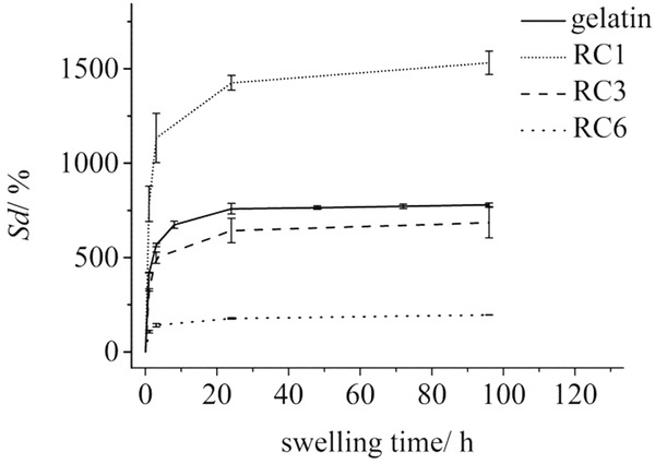
Degree of hydrogel swelling plotted as a function of the swelling time at 25 °C for different samples with a gelatin concentration of 10 wt%. The equilibrium swelling degrees Sd (%) for the plotted samples are 779.2 ± 9.6 (gelatin), 1531.4 ± 62.0 (RC 1), 684.65 ± 80.84 (RC 3) and 195.64 ± 0.26 (RC 6).
2.7 Simulation Studies
We performed molecular simulation studies of Fe2+/Fe3+ and hydroxide ion association to a triple helical (Gly-Hyp-Pro)n peptide to characterize the interplay of collagen and inorganic nanoparticle formation on the molecular scale. To allow direct comparison, the collagen fragment and the simulation method is chosen in full analogy to earlier studies on calcium and phosphate ion association to collagen.63 From this, favorable association sites for both FeII(OH)2 and FeIII(OH)3 ion clusters were identified. Figure 9 illustrates representative constellations as observed for each species. It is noteworthy, that both precursors to magnetite bind to collagen via hydrogen bonds and salt bridges without distorting the triple helix. Instead, Fe(OH)x binds to carbonyl and hydroxyl groups which oxygen atoms tend to complete an octahedral coordination polyhedral for either Fe3+ and Fe2+ association. The close interplay of Fe(OH)x motifs and collagen as observed from molecular simulation hints at the suitability of collagen to bind iron and hydroxide ions (with the later only forming stable bonds in combination with iron ions). From this we conclude that collagen acts as a nucleation seed to iron hydroxide aggregation, and thus intergrowth of collagen and magnetite nanoparticles already at the precursor stage. Moreover, the TEM micrographs of the final magnetite-collagen composites indicate a structural alignment of the nanoparticles (Figure 3), which we attribute to magnetite nucleation along collagen fibers. This interplay of organic and inorganic components could give rise to hierarchical composites as observed for calcium phosphate–collagen based biominerals.64
Figure 9.
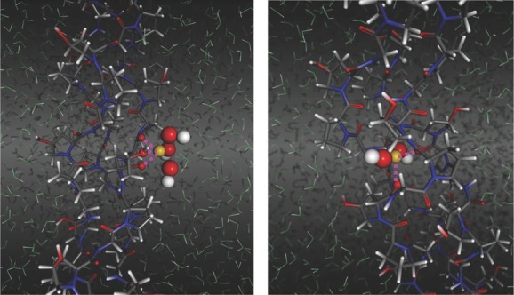
(left) Representative structure for FeIII(OH)3 coordination by collagen. Note that three carbonyl/hydroxyl groups are providing O·Fe salt bridges via one short (2.3 Å) and two weaker (2.6 Å) contacts. (right) FeII(OH)2 cluster coordination by collagen leading to distorted/incomplete octahedral coordination of FeII (the number of coordinating water molecules from the solvent varies from 0 to 2). Atom colors: Fe (yellow), O (red/green for solvent), H (white), N(blue) and C(grey).
3 Conclusions
We have reported a simple synthesis procedure to produce ferrogels with a biocompatible gelatin gel matrix and magnetite nanoparticels. The repetition of the reaction cycles (RC) allows variation of the mineral content between 20 wt% (1 RC) to 70 wt% (8 RC) to form a highly mineralized inorganic-organic hybrid material. Since gelatin gels are thermoreversible, they can be moulded into any shape prior to mineralization which is a big advantage concerning applications. Once they are mineralized, their melting following a temperature decrease is significantly hindered likely due to the introduction of additional crosslinks introduced by the interaction of the magnetite nanoparticles with the gelatin matrix. The structure of the ferrogels was characterized with respect to gelatin as well as magnetite nanoparticles using SANS contrast matching, which is able to individually access the structure of each individual compound over the entire colloidal range as well as SAXS only visualizing magnetite. SANS shows with respect to gel concentration an unchanged gelatin structure of average mesh size larger than the nanoparticles. The size of the nanoparticles seems to be limited by the gel mesh size and independent of gelatin concentration between 6 and 18 wt%. SANS shows no aggregation of magnetite in agreement with TEM. Magnetite particles itself show spatial correlations in SANS and SAXS due to excluded volume interaction, which particularly become strong for the dry samples. The corresponding structure factor is described on basis of hard core interaction. The structural parameters of the gelatin hydrogel are compiled in Table S1, which were determined from the USANS and SANS data in Figure 1 and S3a. Increasing the gel concentration between 6 and 30 wt% forms hydrogel networks of enhanced radii of gyration between 156 and 191 nm. The scattering of the network shows a Q−3 power law indicating a mass fractal structure of the network.43 The scattering at large Q delivers a mesh size of about 20 nm for all gel samples. A similar SANS study on hydrogels is found in a recent publication.65
SQUID measurements showed that the NPs are superparamagnetic as expected for this particle size and have a similar blocking temperature as compared to pure magnetite in this size range. The saturation magnetization of the synthesized NPs is lower than that for bulk magnetite which is likely a result of surface defects of the nanoparticles.
Swelling measurements showed that the adsorption of the magnetic nanoparticles onto the polymeric matrix influences and limits the swelling behavior of the ferrogels. This supports the finding that the gelatin gels lose their thermoreversible properties after magnetite inclusion as additional crosslinker. The degree of swelling can consequently be controlled by the amount of mineral inside the biopolymer. Therefore we can vary the mechanical properties of the ferrogels, which is topic of a subsequent study.
Overall, we have succeeded in the simple preparation of gelatin-based ferrogels with a constant gel structure, but the possibility of a largely varying mineral content. Since the mineral particles are not washed out and also, the gelatin based ferrogels do not dissolve anymore even in an excess of water due to their additional electrostatic crosslinking by the nanoparticles, they have promising applications as biocompatible actuators which can be driven by external magnetic fields as can be seen in Figure 10.
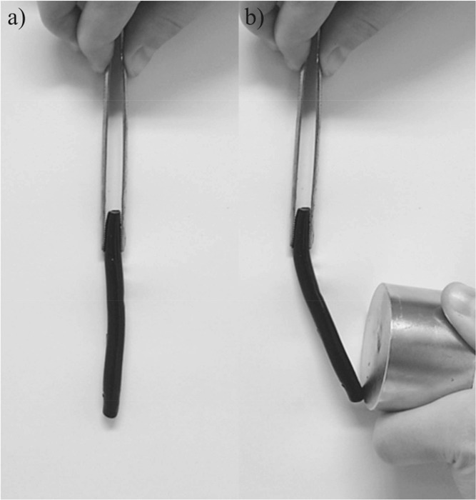
Attraction of ferrogel with a) no magnetic field and b) external magnetic field (ca. 1T)
4 Experimental Section
Chemicals: The following commercially available chemicals were purchased and applied in the synthesis without further purification: FeCl2·4H2O (Sigma-Aldrich), FeCl3·6H2O (Sigma-Aldich), 0.1 M NaOH solution (Merck), Gelatin Type B (∼225 Bloom, Sigma-Aldrich), 4-chloro-m-cresol (Fluka), Methanol (VWR). For the preparation of the reactant solutions double-distilled and deionized (Milli-Q) water was used. All solutions were degassed with argon before usage.
Gel Synthesis: Different amounts of gelatin were allowed to swell in water for 24 hours at 6 °C. Homogeneous solutions were prepared by heating these gels for 2 hours at 50 °C. In each case, 2 mL of solution is filled in disposable base molds (30 mm × 24 mm × 5 mm) and allowed to form a gel there. To avoid decomposition by bacteria, a 5 wt% solution of 4-chloro-m-chresol in methanol was added (0.15 mL per 1 g of dry gelatin).
Synthesis of Ferrogel: In situ mineralization of magnetite nanoparticles in gelatin hydrogel was carried out via co-precipitation of FeCl2 and FeCl3. Each gelatin hydrogel sample was introduced into a solution, containing FeCl2 (0.1 M) and FeCl3 (0.2 M), where it was left for 96 hours at 6 °C. The iron (II) and iron (III)-loaded gels were washed with water and placed in 0.1 M NaOH solution for 150 min.
Transmission Electron Microscopy (TEM): For TEM and HR-TEM analysis, a Zeiss Libra 120 operating at 120 keV and a JEOL JEM-2200FS operating at 200 keV were used, respectively. For material characterization, two distinct sample preparation techniques were applied. On the one hand, a drop of a diluted dispersion of magnetic nanoparticles extracted from the hydrogel was placed on a Formvar coated copper grid and left to dry on a filter paper. On the other hand, the grid was dipped inside the hydrogel matrix and aliquots were blotted using a filter paper. For micro-cut preparation, the ethanol dehaydrated ferrogel samples were embedded in LR white Resin (Medium Grade) and cut with a Leica EM Trim.
Scanning Electron Microscopy (SEM): For SEM analysis a Zeiss Neon 40 EsB operating in high vacuum was used. An InLens and SE detector was used for signal collection and an acceleration voltage of 2 kV was chosen for recording the images. The specimens were coated with a thin layer of gold in order to avoid charging effects.
Thermogravimetric Analysis (TGA): The mineral content of the hydrogels was determined by means of TGA (Netzsch, Selb, Germany). Measurements were carried out at a heating rate of 5 K/min under a constant oxygen flow. Samples were scanned from 293 K to 1273 K.
Small-Angle Neutron Scattering SANS and USANS: Neutron experiments were carried out at, respectively, the KWS1 and KWS 3 diffractometers of JCNS outstation at FRM II in Garching, Germany.66 Three configurations were used at KWS 1, namely the sample-to-detector (SD) distances of 2, 8 and 20 m, the corresponding collimation length of 8 and 20 m, and a wavelength of 0.7 nm (Δλ/λ = 10%). These settings allowed covering a Q-range from 0.02 to 3.5 nm−1. The scattering vector Q is defined as  with the scattering angle δ and the wavelength λ. A two-dimensional local sensitive detector was used to detect neutrons scattered from sample solutions. Gel solutions were filled in rectangular quartz cells with path-length of 1 or 2 mm. Plexiglas was used as secondary standard to calibrate the scattering intensity in absolute units. The data correction and calibration were performed using the software QtiKWS (V. Pipich (2013)).67 In order to cover the broader length scale of the network structure, ultra-small-angle Neutron scattering (USANS) experiments were carried out at the KWS3 diffractometer using parabolic mirror as an optical element, and covering the smaller Q range from 0.001 to 0.02 nm−1.66
Small-Angle X-ray Scattering (SAXS): SAXS experiments were carried out at a HECUS S3-Micro small-angle X-ray scattering instrument. The instrument uses Cu Kα radiation (0.154 nm) produced in a sealed tube. Gel samples were placed in Hilgenberg quartz capillaries with an outside diameter of 1 mm and wall thickness of 0.01 mm. The scattered intensity was corrected with the transmission of the samples calculated considering the absorption of the sample and that of the capillary. The dry gel samples were cut to a thin film with a thickness of 1 mm and measured directly. The scattered X-rays are detected with a two-dimensional multiwire area detector and afterwards converted to one-dimensional scattering by radial averaging and represented as a function of momentum transfer vector Q similar to the SANS experiments.
Magnetization Studies Using Superconducting Quantum Interference Device (SQUID): Magnetization measurements were carried out by using a quantum design SQUID 5 T magnetic properties measurement system (MPMS). For measurements, dried ferrogels were introduced into gelatin capsules and magnetization loop measurements at 2 K and 293 K were performed. In addition zero-field-cooled and field-cooled curves were obtained by applying 0.01 T and heating or cooling the sample.
Swelling Studies: For the drying process the gel samples were left at room temperature for at least 5 days. Air-dried samples of different concentrations of gelatin hydrogel, iron-loaded hydrogel and ferrogels with different numbers of reaction cycles were weighed in the dry state. The samples were left for swelling in 30 ml Milli Q water in a closed vessel at RT. Before weighing, the excess water of each sample was removed with a filter paper. All samples were weighed after a certain amount of time until equilibrium swelling was reached.
Molecular Simulation: a series of FeIII(OH)x(OH2)4-x and FeII(OH)y(OH2)8-y clusters were pre-modeled from ab-initio calculations in vacuum. For all clusters, the high-spin constellation was identified as preferred by several electron volts. Imposing overall charge neutrality (i.e. x+y = 3+2) we found the neutral FeIII(OH)3 · H2O and FeII(OH)2 · 6 H2O clusters as energetically preferred. Docking to collagen was modeled in aqueous solution using empirical force-fields.68 Investigation of biologically-designed metal-specific chelators for potential metal recovery and waste remediation applications,69 and the Kawska-Zahn docking procedure were described previously.70 Along this line, ion clusters are initially docked to collagen in absence of water. Such putative association complexes are then immersed in aqueous solution (periodic simulation cell comprising more than 15 000 water molecules) and subjected to relaxation from 100 ps molecular dynamics runs at room temperature and ambient pressure. To account for the manifold of possible arrangements intrinsic to the systems complexity, a series of 100 independent docking runs were performed for each ionic species. The resulting structures were then classified in terms of hydrogen bonds and O·Fe distances to discriminate the representative configurations of the FeIII(OH)3 · O (collagen) and FeII(OH)2 · O (collagen or H2O) coordination constellations as shown in Figure 9.
Acknowledgments
Many thanks go to A. Laptev (University of Konstanz) for performing the SQUID measurements and M. Krumova (University of Konstanz) for microtomy services. The authors thank Armin Kriele (Materials Science Lab, MLZ, HZG/TUM) for supervision during SAXS measuremments. This work was supported by the Deutsche Forschungsgemeinschaft within the priority program SPP 1569 “Generation of Multifunctional Inorganic Materials by Molecular Bionics” and by the Max Planck Society and the European Research Council through a Starting Grant to DF (256915-MB2).
Supporting Information
As a service to our authors and readers, this journal provides supporting information supplied by the authors. Such materials are peer reviewed and may be re-organized for online delivery, but are not copy-edited or typeset. Technical support issues arising from supporting information (other than missing files) should be addressed to the authors.
Supplementary
References
- 1.Weiner S, Lowenstam HA. On Biomineralization. Oxford: Oxford University Press; 1989. [Google Scholar]
- 2.Addadi L, Weiner S. Angew. Chem. Int. Ed. 1992;31:153. [Google Scholar]
- 3.Aizenberg J, Weaver JC, Thanawala MS, Sundar VC, Morse DE, Fratzl P. Science. 2005;309:275. doi: 10.1126/science.1112255. [DOI] [PubMed] [Google Scholar]
- 4.Wang QQ, Nemoto M, Li DS, Weaver JC, Weden B, Stegemeier J, Bozhilov KN, Wood LR, Milliron GW, Kim CS, DiMasi E, Kisailus D. Adv. Funct. Mater. 2013;23:2908. [Google Scholar]
- 5.Addadi L, Joester D, Nudelman F, Weiner S. Chem. Eur. J. 2006;12:981. doi: 10.1002/chem.200500980. [DOI] [PubMed] [Google Scholar]
- 6.Li H, Xin HL, Muller DA, Estroff LA. Science. 2009;326:1244. doi: 10.1126/science.1178583. [DOI] [PubMed] [Google Scholar]
- 7.Kim Y-Y, Ganesan K, Yang P, Kulak AN, Borukhin S, Pechook S, Ribeiro L, Kröger R, Eichhorn SJ, Armes SP, Pokroy B, Meldrum FC. Nat. Mater. 2011;10:890. doi: 10.1038/nmat3103. [DOI] [PubMed] [Google Scholar]
- 8.Peppas NA, Hilt JZ, Khademhosseini A, Langer R. Adv. Mater. 2006;18:1345. [Google Scholar]
- 9.Seliktar D. Science. 2012;336:1124. doi: 10.1126/science.1214804. [DOI] [PubMed] [Google Scholar]
- 10.Slaughter BV, Khurshid SS, Fisher OZ, Khademhosseini A, Peppas NA. Adv. Mater. 2009;21:3307. doi: 10.1002/adma.200802106. [DOI] [PMC free article] [PubMed] [Google Scholar]
- 11.Mohan YM, Premkumar T, Lee K, Geckeler KE. Macromol. Rapid Commun. 2006;27:1346. [Google Scholar]
- 12.Sahiner N. Prog. Polym. Sci. 2013;38:1329. [Google Scholar]
- 13.Sahiner N. Colloid Polym. Sci. 2006;285:283. [Google Scholar]
- 14.Wu W, Aiello M, Zhou T, Berliner A, Banerjee P, Zhou S. Biomaterials. 2010;31:3023. doi: 10.1016/j.biomaterials.2010.01.011. [DOI] [PubMed] [Google Scholar]
- 15.Zhang D, Yang J, Bao S, Wu Q, Wang Q. Sci. Rep. 2013;3 doi: 10.1038/srep01399. [DOI] [PMC free article] [PubMed] [Google Scholar]
- 16.Breulmann M, Cölfen H, Hentze H-P, Antonietti M, Walsh D, Mann S. Adv. Mater. 1998;10:237. [Google Scholar]
- 17.Thevenot J, Oliveira H, Sandre O, Lecommandoux S. Chem. Soc. Rev. 2013;42:7099. doi: 10.1039/c3cs60058k. [DOI] [PubMed] [Google Scholar]
- 18.Jones F, Cölfen H, Antonietti M. Colloid Polym. Sci. 2000;278:491. [Google Scholar]
- 19.Hu S-H, Liu T-Y, Liu D-M, Chen S-Y. Macromolecules. 2007;40:6786. [Google Scholar]
- 20.Prozorov T, Mallapragada SK, Narasimhan B, Wang L, Palo P, Nilsen-Hamilton M, Williams TJ, Bazylinski DA, Prozorov R, Canfield PC. Adv. Funct. Mater. 2007;17:951. [Google Scholar]
- 21.Biffis A, Orlandi N, Corain B. Adv. Mater. 2003;15:1551. [Google Scholar]
- 22.Sahiner N, Butun S, Ozay O, Dibek B. J. Colloid Interface Sci. 2012;373:122. doi: 10.1016/j.jcis.2011.08.080. [DOI] [PubMed] [Google Scholar]
- 23.Firouzabadi H, Iranpoor N, Gholinejad M, Kazemi F. RSC Adv. 2011;1:1013. [Google Scholar]
- 24.Kazimierska EA, Ciszkowska M. Electroanalysis. 2005;17:1384. [Google Scholar]
- 25.Zhao X, Ding X, Deng Z, Zheng Z, Peng Y, Long X. Macromol. Rapid Commun. 2005;26:1784. [Google Scholar]
- 26.Bock N, Riminucci A, Dionigi C, Russo A, Tampieri A, Landi E, Goranov VA, Marcacci M, Dediu V. Acta Biomater. 2010;6:786. doi: 10.1016/j.actbio.2009.09.017. [DOI] [PubMed] [Google Scholar]
- 27.Sapir Y, Cohen S, Friedman G, Polyak B. Biomaterials. 2012;33:4100. doi: 10.1016/j.biomaterials.2012.02.037. [DOI] [PMC free article] [PubMed] [Google Scholar]
- 28.Reddy NN, Mohan YM, Varaprasad K, Ravindra S, Joy PA, Raju KM. J. Appl. Polym. Sci. 2011;122:1364. [Google Scholar]
- 29.Satarkar NS, Zach Hilt J. Acta Biomater. 2008;4:11. doi: 10.1016/j.actbio.2007.07.009. [DOI] [PubMed] [Google Scholar]
- 30.Kost J, Wolfrum J, Langer R. J. Biomed. Mater. Res. 1987;21:1367. doi: 10.1002/jbm.820211202. [DOI] [PubMed] [Google Scholar]
- 31.De Paoli VM, De Paoli Lacerda SH, Spinu L, Ingber B, Rosenzweig Z, Rosenzweig N. Langmuir. 2006;22:5894. doi: 10.1021/la060280h. [DOI] [PubMed] [Google Scholar]
- 32.Sahiner N, Butun S, Ilgin P. Colloids Surf. A. 2011;386:16. [Google Scholar]
- 33.Li S, Liu X, Huang W, Li W, Xia X, Yan S, Yu J. Polym. Adv. Technol. 2011;22:2439. [Google Scholar]
- 34.Ozay O, Ekici S, Baran Y, Kubilay S, Aktas N, Sahiner N. Desalination. 2010;260:57. [Google Scholar]
- 35.Lao LL, Ramanujan RV. J. Mater. Sci. Mater. Med. 2004;15:1061. doi: 10.1023/B:JMSM.0000046386.78633.e5. [DOI] [PubMed] [Google Scholar]
- 36.Ang KL, Venkatraman S, Ramanujan RV. Mater. Sci. Engin. C. 2007;27:347. [Google Scholar]
- 37.Szabó D, Szeghy G, Zrínyi M. Macromolecules. 1998;31:6541. [Google Scholar]
- 38.Varga Z, Fehér J, Filipcsei G, Zrínyi M. Macromol. Symp. 2003;200:93. [Google Scholar]
- 39.Djabourov M. Contemporary Phys. 1988;29:273. [Google Scholar]
- 40.Babel W. Chem. unserer Zeit. 1996;30:86. [Google Scholar]
- 41.Alefeld B, Schwahn D, Springer T. Nuclear Instruments Methods Phys. Res. A. 1989;274:210. [Google Scholar]
- 42.Beaucage G. J. Appl. Crystallogr. 1995;28:717. [Google Scholar]
- 43.Roe RJ. Methods of X-ray and Neutron Scattering in Polymer Acience. New York: Oxford University Press; 2000. [Google Scholar]
- 44.Li Y, Huang G, Zhang X, Li B, Chen Y, Lu T, Lu TJ, Xu F. Adv. Funct. Mater. 2013;23:660. [Google Scholar]
- 45.Gaihre B, Khil MS, Kang HK, Kim HY. J. Mater. Sci. Mater. M. 2009;20:573. doi: 10.1007/s10856-008-3565-4. [DOI] [PubMed] [Google Scholar]
- 46.Olsson RT, Samir MAAzizi, Salazar-Alvarez G, Belova L, Strom V, Berglund LA, Ikkala O, Nogues J, Gedde UW. Nat. Nanotechnol. 2010;5:584. doi: 10.1038/nnano.2010.155. [DOI] [PubMed] [Google Scholar]
- 47.Sivudu KS, Rhee KY. Colloids Surf. A. 2009;349:29. [Google Scholar]
- 48.Reddy NN, Varaprasad K, Ravindra S, Reddy GVS, Reddy KMS, Reddy KMMohan, Raju KM. Colloids Surf. A. 2011;385:20. [Google Scholar]
- 49.Hernández R, Sacristán J, Asín L, Torres TE, Ibarra MR, Goya GF, Mijangos C. J. Phys. Chem. B. 2010;114:12002. doi: 10.1021/jp105556e. [DOI] [PubMed] [Google Scholar]
- 50.Illés E, Tombácz E. J. Colloids Surf. 2006;295:115. doi: 10.1016/j.jcis.2005.08.003. [DOI] [PubMed] [Google Scholar]
- 51.Heiss A, Jahnen-Dechent W, Endo H, Schwahn D. Biointerphases. 2007;2:16. doi: 10.1116/1.2714924. [DOI] [PubMed] [Google Scholar]
- 52.Pipich V, Balz M, Wolf SE, Tremel W, Schwahn D. J. Am. Chem. Soc. 2008;130:6879. doi: 10.1021/ja801798h. [DOI] [PubMed] [Google Scholar]
- 53.Carn F, Boue F, Djabourov M, Steunou N, Coradin T, Livage J, Floquet S, Cadot E, Buhler E. Soft Matter. 2012;8:2930. [Google Scholar]
- 54.Guinier A. X-ray Diffraction in Crystals, Imperfect Crystals, and Amorphous Bodies. New York: Dover; 1994. [Google Scholar]
- 55.Panda RN, Gajbhiye NS, Balaji G. J. Alloys Compounds. 2001;326:50. [Google Scholar]
- 56.Goya GF, Berquó TS, Fonseca FC, Morales MP. J. Appl. Phys. 2003;94:3520. [Google Scholar]
- 57.Cornell RM, Schwertmann U. The Iron Oxides: Structure, Properties, Reactions, Occurrences, and Uses. Weinheim: Wiley-VCH; 2003. [Google Scholar]
- 58.Kim T, Shima M. J. Appl. Phys. 2007;101:09M516. [Google Scholar]
- 59.Cheng F-Y, Su C-H, Yang Y-S, Yeh C-S, Tsai C-Y, Wu C-L, Wu M-T, Shieh D-B. Biomaterials. 2005;26:729. doi: 10.1016/j.biomaterials.2004.03.016. [DOI] [PubMed] [Google Scholar]
- 60.Kang YS, Risbud S, Rabolt JF, Stroeve P. Chem. Mater. 1996;8:2209. [Google Scholar]
- 61.Sun J, Zhou S, Hou P, Yang Y, Weng J, Li X, Li M. J. Biomed. Mater. Res. A. 2007;80A:333. doi: 10.1002/jbm.a.30909. [DOI] [PubMed] [Google Scholar]
- 62.Gee SH, Hong YK, Erickson DW, Park MH, Sur JC. J. Appl. Phys. 2003;93:7560. [Google Scholar]
- 63.Tlatlik H, Simon P, Kawska A, Zahn D, Kniep R. Angew. Chem. Int. Ed. 2006;45:1905. doi: 10.1002/anie.200503610. [DOI] [PubMed] [Google Scholar]
- 64.Kniep R, Simon P. Top. Curr. Chem. 2007;270:73. [Google Scholar]
- 65.Djabourov M, Bonnet N, Kaplan H, Favard N, Favard P, Lechaire JP, Maillard M. J. Phys. II France. 1993;3:611. [Google Scholar]
- 66. https://www.mlz-garching.de, neutron instruments at the Heinz-Maier-Leibnitz Zentrum (MLZ), accessed: December, 2013.
- 67. http://www.qtikws.de, SANS data treatment package, accessed: December 2, 2013.
- 68.Zhao L, Liu L, Sun H. J. Phys. Chem. C. 2007;111:10610. [Google Scholar]
- 69.Hornak V, Abel R, Okur A, Strockbine B, Roitberg A, Simmerling C. Proteins. 2006;65:712. doi: 10.1002/prot.21123. [DOI] [PMC free article] [PubMed] [Google Scholar]
- 70.Tlatlik H, Simon P, Kawska A, Zahn D, Kniep R. Angew. Chem. Int. Ed. 2006;45:1905. doi: 10.1002/anie.200503610. [DOI] [PubMed] [Google Scholar]
Associated Data
This section collects any data citations, data availability statements, or supplementary materials included in this article.
Supplementary Materials
Supplementary


