Abstract
To improve ophthalmic adaptive optics speed and compensate for ocular wavefront aberration of high temporal frequency, the adaptive optics wavefront correction has been implemented with a control scheme including 2 parallel threads; one is dedicated to wavefront detection and the other conducts wavefront reconstruction and compensation. With a custom Shack-Hartmann wavefront sensor that measures the ocular wave aberration with 193 subapertures across the pupil, adaptive optics has achieved a closed loop updating frequency up to 110 Hz, and demonstrated robust compensation for ocular wave aberration up to 50 Hz in an adaptive optics scanning laser ophthalmoscope.
Adaptive optics (AO) was originally conceived for improving the spatial resolution of astronomy imaging by compensation for the time-varying wavefront aberration induced by the atmosphere turbulence [1]. It has been applied to correct for the wavefront aberration of the living human eye’s optics [2], and enabled diffraction-limited imaging in a variety of retina imaging modalities, including AO flood illumination funds camera [2–4], AO scanning laser ophthalmoscope (AOSLO) [5–7], and AO optical coherence tomography (AOOCT) [8–11]. A major advantage of the AO ophthalmoscopy is that AO can compensate for individual eye’s optical defects that vary person to person, thereby allowing for personalized optimal imaging quality. AO worked with a quasi-static mode in early AO retinal imaging systems in which AO was operated to minimize the static ocular wavefront aberration through several (tens of) loops of iteration and stopped to let the frame grabber to acquire the images [2, 5]. However, the living human eye’s wavefront aberrations are not static but dynamic. Hofer et al assessed the wavefront dynamics using a Shack-Hartmann wavefront sensor with a frame rate of 25.6 Hz [12]. They found that the highest frequency of the ocular wavefront aberration was approximately 5 – 6 Hz. Thus, they suggested that an AO system with a closed-loop bandwidth of 1–2 Hz could correct the aberrations to achieve diffraction-limited imaging. However, Diaz-Santana et al later found that the frequency of the ocular wavefront aberration could be as high as to 30 Hz by measuring the ocular wavefront using a high speed Shack-Hartmann wavefront sensor [13]. Their finding was reverberated by the study conducted by Nirmaier et al [14]. These results indicate that high speed AO correction speed is required for better compensation for high frequency wavefront aberrations thereby further improving the imaging quality.
Advanced control strategy can play a critical role in high-speed AO system. In general, an AO system consists of a wavefront sensor that measures the wavefront shape of the imaging light and a wavefront compensator, that ‘nulls’ the aberration [15]. The (residual) aberration is measured continuously by the wavefront sensor and fed to the wavefront compensator continuously, forming a feedback closed-loop. For ophthalmic imaging, a classic wavefront detector is the Shack-Hartmann wavefront sensor and the wavefront compensator is typically a deformable mirror (DM). As a dynamic control system, the temporal bandwidth of AO closed-loop, a measure of how rapidly the correction must be updated, should be sufficiently wide so that the time varying wavefront aberrations can be corrected. Normally, the −3 dB bandwidth of AO system should be 3 to 10 times of the highest frequency of the ocular wavefront aberration [16]. A classic AO loop includes 3 steps that are carried out sequentially, namely, wavefront detection, reconstruction, and compensation [15]. Thus, the AO bandwidth is determined by the time consumed at each step. With the advancement of high-speed DM manufacture technology, e.g., the micro-electric-mechanic-system based DM (Multi-DM series, Boston micromachines Co., Cambridge, MA, USA) or the electric-magnetic DM (Alpao Hi-speed DM series, Alpao SAS, France), the setting time can be less than1ms within +/−5%, implying that the time for single step wavefront compensation(i.e., the DM actuation) is negligible. Thus, AO close-loop frequency fl in sequential operation maybe estimated by 1/(td + tr), where td is the wavefront detection time and tr is the wavefront reconstruction time. In general, td is determined by the light power for wavefront sensing that is ultimately decided by the eye safety limit, the sensitivity of the wavefront sensor camera, and the overall light budget depending on specific imaging system. tr is dominated by the number of subaperture or sampling points over the pupil, the number of pixels within individual subaperture, and the overall number of pixels within the pupil, as well as the number of the actuators of the DM. In most AO retinal imaging systems, the closed-loop updating frequency is less than 30 Hz [3, 4, 6, 7, 9, 17]. To accelerate the AO speed, we present a parallel control structure consisting of 2 independent threads, one contains the wavefront detection (camera exposure), and the other contains wavefront reconstruction (deriving DM actuator commands from the measured wavefront) and compensation (DM actuation). The wavefront sensor is operated with a continuous and independent (from the wavefront reconstruction and compensation) exposure mode, and the wavefront reconstruction and the DM actuation are informed by the end of each exposure period.
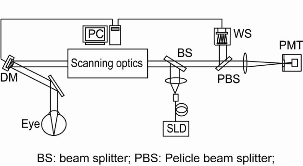
The experiment was conducted with an AOSLO system that has been reported elsewhere [10], as shown in Fig.1. Briefly, the light source for retinal imaging and wavefront sensing is a superluminescent diode (SLD) (Broadlighter S840-HP, Superlum Ltd, Russia). Its center wavelength is at 840 nm and bandwidth is of 50 nm. The light is delivered to the eye through the scanning optics and the DM and forms a scanning raster on the retina. The diffusely reflected light from the retina transmits inversely along the ingoing path to the beam splitter, where most of the light passes through and is relayed to the collection lens. A confocal pinhole is placed at the focal point of the collection lens, and the signal is received by a photomultiplier tube (PMT) (H7422-50, Hamamatsu, Japan), further processed, and acquired by the computer. The pupil size of the instrument is 6 mm in diameter. The AO comprises a DM (Hi-Speed DM97-15, ALPAO SAS, France) and a custom Shack-Hartmann wavefront sensor. The wavefront sensor is made up of a high speed CMOS camera (MicroVista®-NIR, Intevac Inc., USA) whose spectral response is optimized for the near infrared imaging light. A lenslet array of 0.3 mm × 0.3 mm patch and 7.6 mm focal length samples the wavefront in 193 sub-apertures with a 512 × 512 pixel sensor. The influence function was obtained by measuring the wavefront response on the wavefront sensor induced by each individual actuators [18]. Briefly, with a nearly flat wavefront of a model eye that is made up with a lens and a diffuse scatterer placed at the focal plane, each actuator was pushed and pulled, and the corresponding deflection of the light spots on the Shack-Hartmann wavefront sensor was recorded. Listing the deflections of all subapertures over the pupil that were generated by an individual actuator in a column, and putting all the columns that were generate by all actuators together, we thus formed the system influence or interaction matrix. Since there are 193 subapertures and 97 actuators, each subaperture estimates both x and y deflections, the dimensions of influence matrix are 386 × 97. Wavefront reconstruction strategy presented by Li et al [18] was adopted to derive the command for actuating the DM.
Fig.1.
AOSLO system diagram
The CMOS camera of the Shack-Hartmann wavefront sensor operates with a rolling shutter mechanism in which the image data are read out sequentially row by row. All rows of the CMOS sensor have the same amount of exposure time. Once the data in a row are read out, the camera reset this row and starts to integrate light with the set exposure time. Then the row it is accessed again in the next image frame. With the 512 × 512 pixels configuration, the total time for reading data is 7.7 ms, thus the highest frame rate is 129 frames per second. In our application, we operated the camera with an emulated snapshot shutter (or globe shutter) mode. In this mode, if we set an exposure time E ms, all rows will be exposing for (the same) time from time t = 7.7 ms to E. Thus, to ensure a simultaneous exposure, the exposure time should be greater than 7.7 ms. In our system, the minimum exposure time is 8.8 ms, which allows for 1.1 ms simultaneous exposure to all rows of the sensor.
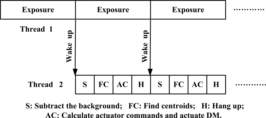
Fig.2 shows the dual threads control structure. One thread is for wavefront detection, and the other for wavefront reconstruction and compensation. These two threads communicate by user defined windows message. The wavefront detection includes 3 steps, light integration, data reading, and camera reset. The wavefront reconstruction involves background subtraction, calculation of the centroids’ positions of the light spots of each subaperture, and calculation of actuator commands. The wavefront compensation is carried out by actuation of the DM. The wavefront sensor camera is set with a continuous exposure mode, serving as the master loop in the two threads. The wavefront reconstruction and compensation thread starts first and turns to hang-up status and waits for wake-up message. Then the wavefront detection thread starts, after integration of the light, it sends a message to trigger wavefront reconstruction and compensation thread. Once the DM is actuated with the commands derived from the wavefront reconstruction, the threads hangs up and waits for next wake-up signal. The system works essentially with a 1-step delay scheme. The total time for wavefront construction and compensation is approximately 6.5 ms: subtraction of background takes 1.5 ms and calculation of centroids’ positions takes 4.5 ms, computation of actuation commends and actuation of the DM take less than 0.5 ms. Thus, with a sequential control, the highest update frequency of the AO closed-loop can be 65 Hz only. With the parallel dual threads algorithm, the AO closed-loop can be operated at a frequency 110 Hz. Table 1 shows the updating frequency tested with the AOSLO in the living human eye.
Fig.2.
Dual threads AO control
Table 1.
AO closed-loop frequency
| Exposure time (ms) | AO loop frequency (Hz) |
|---|---|
| 8.8 | 112.71 |
| 10 | 99.19 |
| 15 | 66.17 |
| 20 | 49.60 |
| 25 | 39.73 |
The imaging light power measured at the cornea was 500 µWatts, which is about 1/26 of the maximum permitted exposure limits set by the ANSI standard. The AOSLO records continuous videos from the eye with a frame rate 15 Hz. An uncoated pellicle beam splitter is used to pick up 8% of the light reflected from the human eye for wavefront measurement. With a closed-loop updating frequency of 110 Hz, AO can reduce the root-mean-square (RMS) wave aberration to less than 50 nm in most eyes, meeting the Maréchal criterion [19], which indicates that when the RMS wave aberration is less than 1/14 wavelength the imaging is diffraction limited.
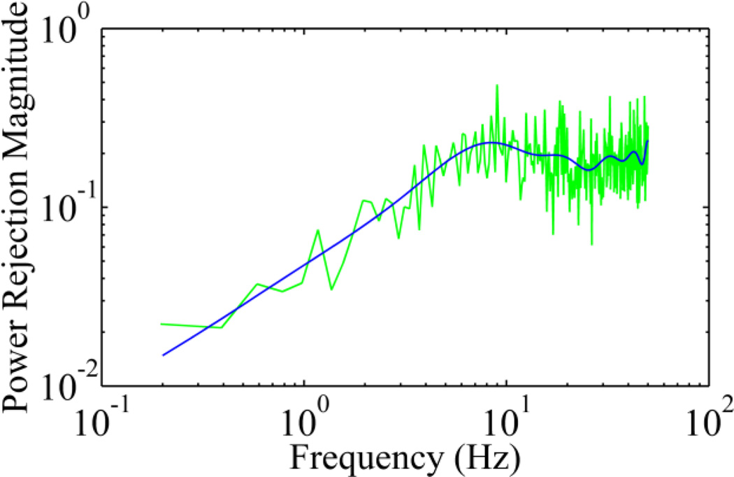
We imaged 5 human subjects with healthy eyes using the AOSLO with the new control algorithm. The study followed the tenets of the Declaration of Helsinki and was approved by the Institutional Review Board at the University of Alabama at Birmingham. Written informed consent was obtained from participants after the nature and possible consequences of the study were explained. Retinal images were acquired under dilatation (one topically applied drop each of 1% tropicamide and 2.5% phenylephrine). Exemplary images of AO correction at 100 Hz are shown in Fig.4. The robust performance of the new AO control algorithm is evidenced by the significantly improved resolution, brightness and contrast. Wavefront aberrations before and after AO correction were recoded. The corresponding components of the Fourier transform of the wavefront aberrations after and before AO correction were compared and expressed as the power rejection ratio, i.e., ωa(f)/ωb(f), where ωa(f) and ωb(f) are the Fourier transform of the RMS wavefront aberrations after and before AO correction, as shown in Fig.5. Evidently, the power rejection ratios of the Fourier components of the aberrations within 0 – 50 Hz are less than 1, indicating that all frequency components were compressed by AO compensation.
Fig.4.
Retinal images taken with the AOSLO. The top panel is a single frame taken before AO correction. The middle is a single frame taken after AO correction. The bottom panel is a registered set of 20 AO-corrected images. All images have been corrected for distortions due to eye movements [20]. These images were taken from a retinal location about 0.5° nasally away from the fovea center. The field of view subtends 0.7°, or approximately 210µm on a side.
Fig.5.
Power rejection ratio of ocular wavefront aberration with AO operating at 100 Hz. The green line is the mean ratios of individual frequency components obtained from the 5 eyes of the study subjects. The blue curve is a fitting of 15 orders of power series.
We have demonstrated a parallel control strategy that enables high-speed AO correction. This is an important step for further improving AO retinal imaging quality. While low-speed AO systems have demonstrated decent correction previously due to the power spectrum of the ocular wavefront aberration concentrating in low frequency region, retinal imaging may still be further benefited from high-speed AO. If the temporal frequency of the ocular aberration is up to 30 Hz, the AO closed-loop updating rate should be at least 90 Hz. To correct for the wavefront aberration precisely, the wavefront should be measured with adequate spatial samplings. Thus, an ideal wavefront sensor should possess fast frame rate and high density spatial subapertures. We should note that a high frame rate of the wavefront sensor camera is important but it is not the sole factor for achieving robust AO correction. Diaz-Santana et al reported a 240 Hz frame rate of their wavefront sensor, but they achieved it on a 128 × 128 pixels sensor with only 21 subapertures over the pupil [13], which is inadequate for compensating for aberrations of high spatial frequency or high order. In our study, we measured the wavefront with 193 subapertures over the pupil using a sensor with 512 × 512 pixels and high frame rates, meeting the spatial and temporal requirement of an AO system.
While we demonstrated the technical advance, we also noted the limitations of our study. First, due to the rolling shutter exposure and data reading mechanism of the CMOS camera, the wavefront detection may be susceptible to certain motion artifacts in measurement of fast wavefront aberrations. Second, because the camera is running with a continuous exposure mode, the actuation of DM happens during the exposure of the camera thus the accuracy of wavefront measurement is affected. Ideally, the camera should receive a message from the wavefront reconstruction and compensation thread to quickly stop and resume light integration, but this camera unfortunately does not possess this capability allowing us to do so. Despite these drawbacks, the retinal image quality is comparable to that acquired with strict sequential AO correction. With new cameras of faster frame rate, higher sensitivity, and more flexible control functions, we may further enhance AO performance and thereby improving retinal image quality.
As a pilot study for improving AO performance, we were unable to provide a quantitative estimation of the benefit of the fast AO bringing in for the retinal image quality. It should note that high-speed AO correction is a necessary but not a sufficient condition for high quality retinal imaging through the living human eye. In addition to the ocular wavefront aberration, other factors such as the clarity of the lens and the vitreous, the uniformity of the team film, and the eye motion, etc., can also impose significant impact on the image quality. For example, even in an emmetropic eye of a young subject, the imaging brightness can be significantly varying within a very short time period due to tear film changing. Under this situation, it is difficult to objectively estimate the improvement brought in by the fast AO through a simple comparison of the retinal images obtained with the fast correction and a slower correction. Thus, we must acknowledge the fact that the benefit of the fast AO is yet to be proven in future study. Nevertheless, high speed is indeed important for high quality imaging theoretically and practically. As proven by previous studies, the high frequency dynamics of the ocular wavefront aberration demands fast AO. High speed updating frequency can facilitate and enhance advanced control algorithm and strategy [21, 22]. Fast AO maybe applied to new imaging system that is very promising to achieve high speed retinal imaging [23].
In conclusion, we have developed a parallel control algorithm for increasing the AO closed-loop speed and demonstrated its robust performance for correcting the ocular wavefront in the living human eye. This method allows us to take full advantage of the speed of the camera thereby allowing for AO correction for ocular aberration of high temporal frequency.
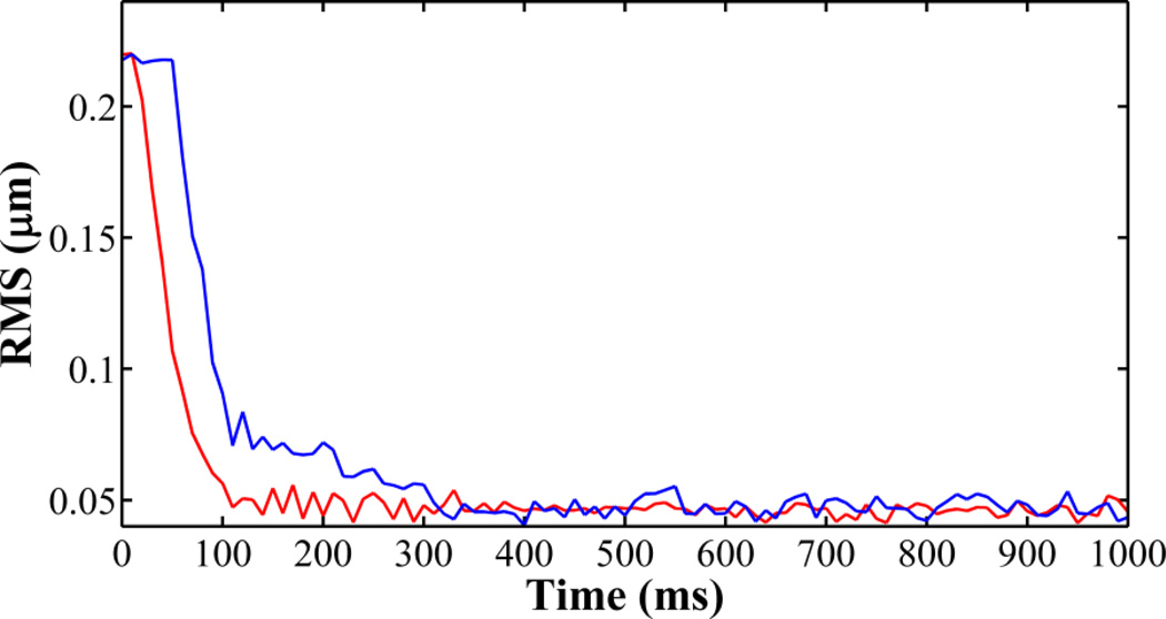
Fig.3.
The RMS traces of AO closed-loop of 100 Hz (red) and 20 Hz (blue) tested with a model eye. When AO is operated at 100 Hz, it reduces the RMS of the wavefront aberration to less than 0.05 µm within 100 ms.
Acknowledgements
This project was supported by funding from EyeSight Foundation of Alabama (YZ), International Retina Research Foundation (YZ), NIH 5R21EY021903 (YZ), and institutional support from Research to Prevent Blindness, EyeSight Foundation of Alabama, Buck Trust of Alabama, and NIH P30 EY003039. Yongxin Yu was supported by a visiting scholarship fund from Tianjin University and the University of Alabama at Birmingham Exchange Scholar Program.
References
- 1.Babcock HW. The possibility of compensating astronomical seeing. Publ. Astron. Soc. Pac. 1953;65:229–236. [Google Scholar]
- 2.Liang J, Williams DR, Miller DT. Supernormal vision and high-resolution retinal imaging through adaptive optics. J. Opt. Soc. Am. A. Opt. Image Sci. Vis. 1997;14:2884–2892. doi: 10.1364/josaa.14.002884. [DOI] [PubMed] [Google Scholar]
- 3.Hofer H, Chen L, Yoon GY, Singer B, Yamauchi Y, Williams DR. Improvement in retinal image quality with dynamic correction of the eye's aberrations. Opt. Express. 2001;8:631–643. doi: 10.1364/oe.8.000631. [DOI] [PubMed] [Google Scholar]
- 4.Rha J, Jonnal RS, Thorn KE, Qu J, Zhang Y, Miller DT. Adaptive optics flood-illumination camera for high speed retinal imaging. Opt. Express. 2006;14:4552–4569. doi: 10.1364/oe.14.004552. [DOI] [PubMed] [Google Scholar]
- 5.Roorda A, Romero-Borja F, Donnelly Iii W, Queener H, Hebert T, Campbell M. Adaptive optics scanning laser ophthalmoscopy. Opt. Express. 2002;10:405–412. doi: 10.1364/oe.10.000405. [DOI] [PubMed] [Google Scholar]
- 6.Zhang Y, Poonja S, Roorda A. MEMS-based adaptive optics scanning laser ophthalmoscopy. Opt. Lett. 2006;31:1268–1270. doi: 10.1364/ol.31.001268. [DOI] [PubMed] [Google Scholar]
- 7.Burns SA, Tumbar R, Elsner AE, Ferguson D, Hammer DX. Large-field-of-view, modular, stabilized, adaptive-optics-based scanning laser ophthalmoscope. J. Opt. Soc. Am. A. Opt. Image Sci. Vis. 2007;24:1313–1326. doi: 10.1364/josaa.24.001313. [DOI] [PMC free article] [PubMed] [Google Scholar]
- 8.Hermann B, Fernández EJ, Unterhuber A, Sattmann H, Fercher AF, Drexler W, Prieto PM, Artal P. Adaptive-optics ultrahigh-resolution optical coherence tomography. Opt. Lett. 2004;29:2142–2144. doi: 10.1364/ol.29.002142. [DOI] [PubMed] [Google Scholar]
- 9.Miller DT, Kocaoglu OP, Wang Q, Lee S. Adaptive optics and the eye (super resolution OCT) Eye. 2011;25:321–330. doi: 10.1038/eye.2011.1. [DOI] [PMC free article] [PubMed] [Google Scholar]
- 10.Meadway A, Girkin CA, Zhang Y. A dual-modal retinal imaging system with adaptive optics. Opt. Express. 2013;21:29792–29807. doi: 10.1364/OE.21.029792. [DOI] [PMC free article] [PubMed] [Google Scholar]
- 11.Shi G, Dai Y, Wang L, Ding Z, Rao X, Zhang Y. Adaptive optics optical coherence tomography for retina imaging. Chin. Opt. Lett. 2008;6:424–425. [Google Scholar]
- 12.Hofer H, Artal P, Singer B, Aragón JL, Williams DR. Dynamics of the eye's wave aberration. J. Opt. Soc. Am. A. Opt. Image Sci. Vis. 2001;18:497–506. doi: 10.1364/josaa.18.000497. [DOI] [PubMed] [Google Scholar]
- 13.Diaz-Santana L, Torti C, Munro I, Gasson P, Dainty C. Benefit of higher closed-loop bandwidths in ocular adaptive optics. Opt. Express. 2003;11:2597–2605. doi: 10.1364/oe.11.002597. [DOI] [PubMed] [Google Scholar]
- 14.Nirmaier T, Pudasaini G, Bille J. Very fast wave-front measurements at the human eye with a custom CMOS-based Hartmann-Shack sensor. Opt. Express. 2003;11:2704–2716. doi: 10.1364/oe.11.002704. [DOI] [PubMed] [Google Scholar]
- 15.Tyson RK. Principles of Adaptive Optics. Boca Raton: CRC Press; 2011. [Google Scholar]
- 16.Golnaraghi F, Kuo BC. Automatic Control Systems. New Jersey: John Wiley & Sons Inc; 2009. [Google Scholar]
- 17.Dubra A, Sulai Y. Reflective afocal broadband adaptive optics scanning ophthalmoscope. Biomed. Opt. Express. 2011;2:1757–1768. doi: 10.1364/BOE.2.001757. [DOI] [PMC free article] [PubMed] [Google Scholar]
- 18.Li KY, Mishra S, Tiruveedhula P, Roorda A. Comparison of Control Algorithms for a MEMS-based Adaptive Optics Scanning Laser Ophthalmoscope. Proc. Am. Control. Conf. 2009:3848, 3853. doi: 10.1109/ACC.2009.5159832. [DOI] [PMC free article] [PubMed] [Google Scholar]
- 19.Shannon RR, Wyant JC. Applied Optics and Optical Engineering. Chapter 6. Vol. 8. New York: Academic Press Inc.; 1980. [Google Scholar]
- 20.Vogel CR, Arathorn DW, Roorda A, Parker A. Retinal motion estimation in adaptive optics scanning laser ophthalmoscopy. Opt. Express. 2006;14:487–497. doi: 10.1364/opex.14.000487. [DOI] [PubMed] [Google Scholar]
- 21.Zou W, Burns SA. High-accuracy wavefront control for retinal imaging with Adaptive-Influence-Matrix Adaptive Optics. Opt. Express. 2009;17:20167–20177. doi: 10.1364/OE.17.020167. [DOI] [PMC free article] [PubMed] [Google Scholar]
- 22.Zheng Z, Li C, Li B, Zhang S. Analysis and demonstration of PID algorithm based on arranging the transient process for adaptiveoptics. Chin. Opt. Lett. 2013;11:110101. [Google Scholar]
- 23.He Y, Li H, Lu J, Shi G, Zhang Y. Retina imaging by using compact line scanning quasi-confocal ophthalmoscope. Chin. Opt. Lett. 2013;11:021101. [Google Scholar]


