Abstract
Background
Metal wear and corrosion products generated by hip replacements have been linked to adverse local tissue reactions. Recent investigations of the stem/head taper junction have identified this modular interface as another possible source of metal debris; however, little is known regarding other modular metallic interfaces, their ability to produce metal debris, and possibly to provide insight in the mechanisms that produce metal debris.
Questions/purposes
We asked three questions: (1) can we develop a reliable method to estimate volumetric material loss from the backside taper of modular metal-on-metal liners, (2) do backside tapers of modular metal-on-metal liners show a quantifiable volumetric material loss, and, if so, (3) how do regions of quantitatively identified material loss correspond to visual and microscopic investigations of surface damage?
Methods
Twenty-one cobalt-chromium (CoCr) liners of one design and manufacturer were collected through an institutional review board-approved retrieval program. All liners were collected during revision surgeries, where the primary revision reason was loosening (n = 11). A roundness machine measured 144 axial profiles equally spaced about the circumference of the taper region near the rim to estimate volume and depth of material loss. Sensitivity and repeatability analyses were performed. Additionally, visual and scanning electron microscopy investigations were done for three liners.
Results
Our measurement method was found to be reproducible. The sensitivity (how dependent measurement results are on experimental parameters) and repeatability (how consistent results are between measurements) analyses confirmed that component alignment had no apparent effect (weak correlation, R2 = 0.04) on estimated volumetric material loss calculations. Liners were shown to have a quantifiable material loss (maximum = 1.7 mm3). Visual investigations of the liner surface could identify pristine surfaces as as-manufactured regions, but could misidentify discoloration as a possible region of material loss. Scanning electron microscopy more accurately distinguished between as-manufactured and damaged regions of the taper.
Conclusions
The roundness machine has been used to develop a repeatable method for characterizing material loss; future work comparing a gravimetric standard with estimations of material loss determined from the roundness machine may show the accuracy and effectiveness of this method. Liners show rates of material loss that compare with those reported for other taper junctions. Visual inspection alone may misidentify as-manufactured regions as regions of material loss.
Clinical relevance
This study identifies the acetabular liner/shell interface in modular metal-on-metal devices as a potential source of metal wear or corrosion products. The relation between metal debris and clinical performance, regardless of the type of bearing couple, is a concern for clinicians. Therefore, it is important to characterize every type of modular junction to understand the quantity, location, and mechanism(s) of material loss.
Introduction
Increased modularity in total hip replacements (THR) has offered surgeons the ability to make intraoperative adjustments to reconstruct leg length and offset [2]. However, evidence of taper damage has been reported in studies that aim to quantify material loss for many types of modular interfaces [3, 4]. This taper damage may contribute to metal release in the body, which has been associated with adverse local tissue reactions [6]. Although backside damage has been reported for polyethylene liners, backside damage of modular acetabular liners in metal-on-metal (MoM) THRs has received little attention.
Primary concerns for device wear historically have focused on the bearing surface, and attempts to quantify material loss from the articulating surfaces of metal-on-metal hip implants have been reported [9, 10, 13]. More recently, volumetric material loss investigations were performed on the taper interface between the femoral head and stem [1, 11, 12, 14]. Higgs et al. [4] reported evidence of visual fretting or corrosion from other junctions, such as the distal and proximal ends of modular femoral necks, adapter sleeves for the femoral head, and the mating surfaces of acetabular liners, and thus other taper junctions may have quantifiable material loss. Backside damage and material loss of modular polyethylene acetabular liners also have been investigated [7, 8, 16]. Kurtz et al. [8] recognized the potential for backside material loss to occur in modular polyethylene liners, and Krieg et al. [7] quantified this backside damage in retrieved components. The concern for backside material loss is primarily with the migration of particles into the effective joint space between the acetabular component and the bone, leading to instances of implant loosening and osteolysis [15]. However, while backside wear has been documented in polyethylene acetabular components, no study, to our knowledge, has reported on material loss from the backside of cobalt-chromium (CoCr) alloy acetabular liners or the clinical consequences. Part of the reason for this might be that, to our knowledge, sensitive, reproducible tools for this task have not been developed.
In this study, we therefore sought to address three questions: (1) can we develop a reliable method to estimate volumetric material loss from the backside taper of modular metal-on-metal liners, (2) do backside tapers of modular metal-on-metal liners show a quantifiable volumetric material loss, and, if so, (3) how do regions of quantitatively identified material loss correspond to visual and microscopic investigations of surface damage?
Patients and Methods
Twenty-one (21) modular metal-on-metal acetabular liners (CoCr alloy) of the Pinnacle® design (Depuy, Warsaw, IN, USA) were collected at revision surgery from 21 patients (13 males and eight females) between 2003 and 2014 in an institutional review board-approved, multiinstitutional retrieval program. All implants of this design that were received from the clinical centers were included in this study. However, not all patients undergoing revision surgery at collaborating institutions chose to participate. Not all patient and implant information could be collected by the retrieval study, so the averages and ranges were qualified if they did not represent the entire cohort.
The causes for revision were loosening (n = 11), instability (n = 2), infection (n = 2), pain (n = 2), periprosthetic fracture (n = 1), and other reasons (n = 3). The average body mass index (BMI) of the patients was 31.8 ± 8.0 kg/m2 and the average activity score for 11 of the 21 patients was 5 ± 2. The University of California, Los Angeles (UCLA), activity score attempts to quantify on a 10-point scale the regularity and rigor of the physical activities in which the patient participates: a score of 10 indicates routine participation in sports and a score of 1 indicates complete inactivity to the point of dependence [17]. Implantation time for 19 of the 21 liners ranged from less than 0.25 to 7.76 years. Corresponding head sizes of the liners were 28 mm (n = 2), 36 mm (n = 10), 40 mm (n = 8), and 44 mm (n = 1) (Table 1). The visual damage score (a semiquantitative analysis of the extent of surface area showing scratches, corrosion, discoloration, and/or other signs of damage) for 15 of these modular liners was reported in a previous study [4]. Using a modified Goldberg visual damage scoring system [3, 5], where scores were assigned from 1 (minimal) to 4 (severe), we found 10 of 15 liners had a score of 2 (mild damage, greater than 10% surface area), four of 15 liners with a score of 3 (moderate damage, greater than 30% surface area), and one of 15 liners with a score of 4 (severe damage, greater than 50% surface area) [4].
Table 1.
Summary of patient and component information
| Component | Gender (M/F) | Surgical site (L/R) | Standardized revision reason | Patient weight (kg) | Patient height (m) | BMI (kg/m2) | Activity score | Implantation time (years) | Implant head diameter (mm) |
|---|---|---|---|---|---|---|---|---|---|
| 1 | M | L | Loosening | 93.0 | 1.85 | 27.0 | 2 | 6.48 | 36 |
| 2 | M | L | Instability | 104.3 | 1.75 | 34.0 | 3 | 2.10 | 44 |
| 3 | F | R | Other | 88.5 | 1.75 | 28.8 | 2 | 2.36 | 36 |
| 4 | M | R | Loosening | 70.3 | 1.75 | 22.9 | – | 1.49 | 36 |
| 5 | F | R | Loosening | 72.6 | 1.75 | 23.6 | 6 | 5.18 | 36 |
| 6 | M | L | Other | 113.4 | 1.91 | 31.2 | 7 | 0.62 | 40 |
| 7 | M | R | Instability | 106.6 | 1.88 | 30.2 | 2 | 4.62 | 36 |
| 8 | F | L | Pain | 85.3 | 1.60 | 33.3 | – | – | 36 |
| 9 | M | L | Pain | 147.0 | 1.75 | 47.8 | – | 5.81 | 36 |
| 10 | F | L | Infection | 126.6 | 1.55 | 52.7 | 3 | 0.00 | 28 |
| 11 | M | L | Loosening | 90.7 | 1.83 | 27.1 | 6 | 2.83 | 40 |
| 12 | M | L | Infection | 71.7 | 1.75 | 23.3 | – | 4.00 | 36 |
| 13 | M | R | Periprosthetic fracture | 144.2 | 1.83 | 43.1 | – | – | 40 |
| 14 | F | R | Loosening | 83.9 | 1.60 | 32.8 | – | 1.00 | 36 |
| 15 | M | R | Loosening | 94.8 | 1.60 | 37.0 | – | 1.25 | 40 |
| 16 | F | R | Loosening | 55.3 | 1.63 | 20.9 | – | – | 40 |
| 17 | M | L | Loosening | 105.7 | 1.85 | 30.7 | – | 0.75 | 40 |
| 18 | M | L | Loosening | 104.3 | 1.83 | 31.2 | 8 | 3.50 | 40 |
| 19 | M | L | Loosening | 104.3 | 1.80 | 32.1 | 8 | 3.00 | 40 |
| 20 | F | L | Malalignment | 83.0 | 1.65 | 30.4 | 3 | 7.76 | 28 |
| 21 | F | L | Loosening | 76.2 | 1.65 | 28.0 | – | 5.25 | 36 |
A Talyrond® 585 roundness machine (Taylor-Hobson, Leicester, UK) was selected to measure the surface of the taper region of the acetabular liners because the precision air spindle (radial limit of error, ± 0.030 µm), vertical column (straightness, 0.15 µm/100 mm), and stylus gauge (with arcuate calibration, resolution, 0.008 µm) allowed for precise measurement of cylindrical surfaces. The position of the radial arm was calibrated.
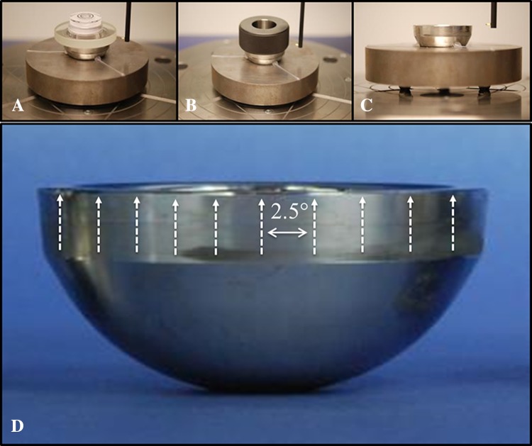
The liners were mounted on a fixture on the Talyrond® rotating table with the distal end facing upward. Centering and leveling of all components, which aligns the Talyrond® axis of rotation with the axis of rotational symmetry of the liners, was achieved systematically through the following process: manual alignment using a bulls-eye bubble level placed on the rim of the component to manually level the component; the bubble level then was replaced by a ring gauge (precision class XXX), with a bore perpendicular to the face, which was centered and leveled using the ‘auto center and level’ procedure in the Ultra software (Taylor-Hobson); final levelness verification or adjustments were made through the cylindricity data produced by several roundness profiles taken at different points along the length of the taper. Liners were leveled to an average 30.9 ± 10.1 seconds of 90°, where 90° represents a component whose part axis is perfectly aligned with the spindle axis of the roundness machine. The largest deviation in alignment was 50.4 seconds. One hundred forty-four axial profiles equally spaced every 2.5° (arc length = 1.0–1.4 mm) then were measured about the circumference of the modular liner in the taper region near the rim (Fig. 1).
Fig. 1A–D.
The alignment procedure used in this study progressed from: (A) manual alignment to the (B) auto center and level of a ring gauge to (C) creation of a part datum from circumferential profiles. (D) This is a representation of the direction of the axial traces and their spacing about the circumference of the taper (not to scale).
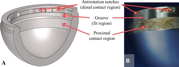
A customized MATLAB® (The Mathworks Inc, Natick, MA, USA) algorithm was developed to analyze the axial profiles and estimate volumetric material loss and maximum depth of material loss. Each axial profile was assumed to represent the surface of the taper until the following profile was acquired; in the case of this study each profile represented 1/144 of the liner surface. The algorithm fitted a least squares regression line to the region of the profiles (the fit region) that were assumed to represent the as-manufactured surface of the taper. A straight taper geometry was confirmed from liner measurements with no material loss. The as-manufactured regions were identified by trained operators who examined the liner and mating shell taper geometry to determine the probable points of contact and compared this contact geometry with the topography of the axial profiles. Knowledge gained through examination of the mating taper surface of the acetabular shell indicated that a region in the middle of the taper would not be contacted under normal circumstances, which aided in identification of the as-manufactured surface (Fig. 2). The area between the measured profile and the regression line (estimating the as-manufactured surface) was calculated, along with the volume of the partial annulus revolved to the next profile. The volume of each of the partial annuli was added together to estimate the volumetric material loss. The area above the regression line, which was assumed to represent the as-manufactured taper surface, was considered negative material loss, ie, adhered material (subtracted volume in volumetric calculations), and area below the regression line was considered positive material loss, ie, lost material (adding to volumetric material loss), giving an estimate of volumetric material loss.
Fig. 2A–B.
Knowledge of the component geometry was used to identify likely locations for the as-manufactured regions. (A) A cross-sectional schematic view of the acetabular shell shows the mating surface for the modular liners. (B) A photograph of a liner taper where damaged regions, corresponding to the points of contact with the acetabular shell, may be clearly identified.
A sensitivity analysis was performed to assess the effects of measurement parameters (component alignment) and computation inputs (length and placement of the fit region) on the estimated volumetric material loss of the liner tapers. The effect of component angular alignment was investigated by measuring the same component several times and varying the levelness through a 3-minute (0.05°) range. All other conditions and calculation parameters remained constant.
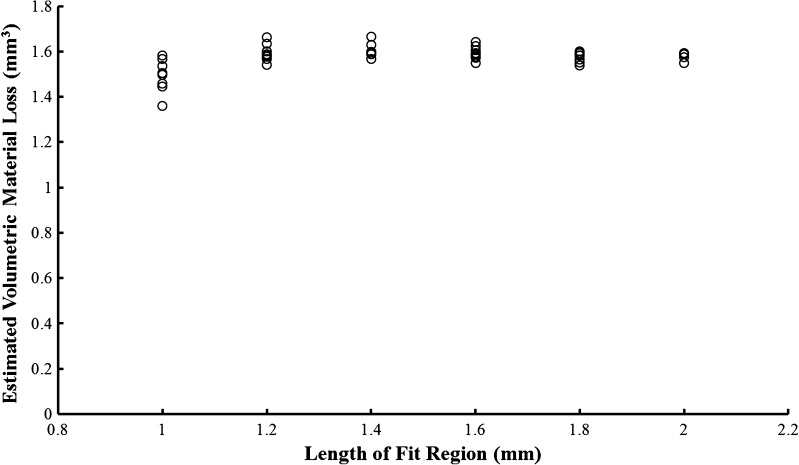
The user-defined fit region used for the least squares regression line in the MATLAB® analysis was identified as a potential source of variability in material loss calculations. To evaluate the magnitude of this variability, a component was measured according to procedure but the length and placement of the regions used to fit the least squares line representing the as-manufactured taper were varied during analysis. The investigation of the length and placement of the fit region on the axial profile was performed using the most damaged liner with presumably the smallest available fit region (2 mm). Four data sets acquired from this component were analyzed. The fit region was increased from 1.0 to 1.8 mm and placed so that the start of the fit region was at the beginning of the as-manufactured region and also so that the end of the fit region was at the end of the as-manufactured region, providing the most extreme permutations that could exist in the placement of the fit region. A final calculation was made using the entire 2.0 mm as-manufactured region; obviously no permutation exists for this fit length. The range in variability decreased from 14.1 % to less than 3.0 % when length of fit region was increased from 1.0 mm to 2.0 mm (Fig. 3). For this reason, the length of all fit regions in this study was kept to 2.0 mm.
Fig. 3.
The effect of length and placement of the selected fit region on estimated volumetric material loss is shown. Variability decreased with each sequential increase in length.
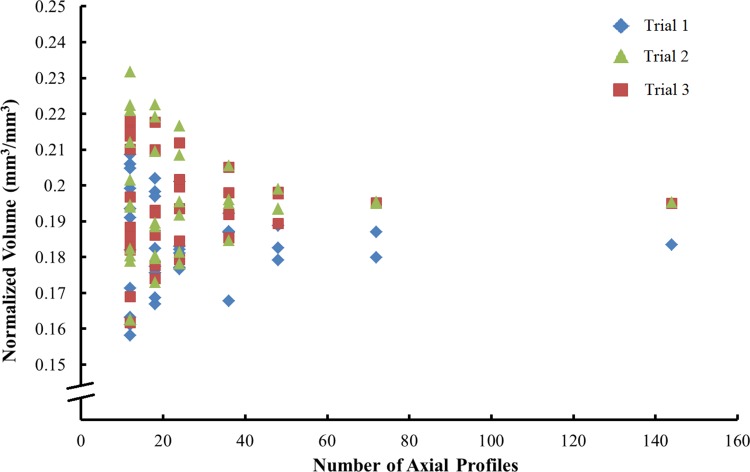
Finally, a repeatability study was performed to evaluate the reliability of estimating volumetric material loss from 144 axial profiles. Keeping levelness, fit length (2 mm), and number of scans (n = 144) constant, the same component was measured three times (Trials 1, 2, and 3). The sensitivity of material loss calculations to the number of profiles used was assessed by systematically excluding profiles so that simulated results of evenly spaced measurements were obtained over a range of 5° to 24°.
Visual and photographic investigations of taper junctions and scanning electron microscopy (Zeiss Supra 50VP; Carl Zeiss, Germany), were performed for three liners. Visual examination identified distinguishing features on the taper surface such as staining or apparent changes in topography. The secondary electron detector of the scanning electron microscope was used to corroborate visual assessments. Imaging was then compared with axial profiles of the region taken by the roundness machine. After analysis of three components we were confident in our ability to determine as-manufactured regions of the component from visual (identification of pristine surfaces) and roundness machine investigations (characteristic typography of machining marks), while showing that visual analysis cannot necessarily discern between staining and changes in surface topography. For these reasons, we did not think that additional microscopy investigations would add to the content of our study.
Results
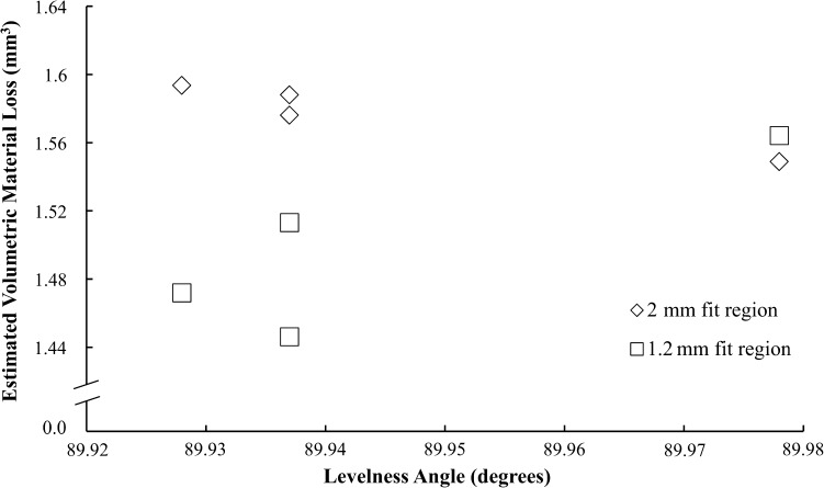
Our measurement method was found to be reproducible. No substantial dependence of estimated material loss on levelness was observed (Fig. 4). Regression analysis of this preliminary study showed a weak correlation (R2 = 0.04) of material loss calculations to levelness, with a high estimate of sensitivity to be 0.6 mm3/degree. The repeatability analysis showed the precision of this method to estimate the volumetric material loss at the modular junction of metal-on-metal acetabular liners. The variability decreased from 7.4 % to 1.2 % as the number of axial profiles used in the MATLAB® analysis was increased from 15 to 144 (Fig. 5).
Fig. 4.
The sensitivity analysis of volumetric calculations to component alignment showed a weak correlation (R2 = 0.04).
Fig. 5.
Normalized volumetric material loss was calculated using 15 to 144 axial profiles. Three trials of 144 measurements were made on one component. The other data were simulated by excluding various numbers of axial traces from the data set; as there are permutations of which traces can be excluded, some simulations have more data points than others.
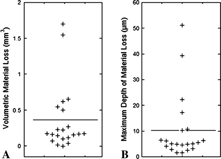
The taper interface of modular MoM acetabular liners was shown to have quantifiable volumetric material loss obtained through a reliable and repeatable method. The range in estimated material loss was 0.0 mm3 to 1.7 mm3 (Fig. 6A), with a mean estimated material loss of 0.4 mm3 and median of 0.2 mm3. Rates of material loss calculated for 18 of 21 liners ranged from 0.0 mm3 to 1.2 mm3 per year (Table 2), with a mean and median of 0.2 mm3 and 0.1 mm3 per year, respectively. The maximum observed depth of material loss was 51.2 µm (Fig. 6B). A positive correlation between wear rate and BMI was found (ρ = 0.56, p = 0.02), although no other correlations were found between material loss metrics and patient or implant factors.
Fig. 6A–B.
(A) Average volumetric material loss and (B) maximum depth of material loss are shown. The horizontal line indicates the mean for the entire cohort.
Table 2.
Linear and volumetric results calculated from the axial profiles
| Component | Maximum observed depth of material loss (μm) | Calculated volumetric material loss (mm3) | Calculated rate of material loss (mm3/year) |
|---|---|---|---|
| 1 | 6.5 | 0.12 | 0.02 |
| 2 | 5.0 | 0.23 | 0.11 |
| 3 | 4.9 | 0.17 | 0.07 |
| 4 | 3.2 | 0.22 | 0.15 |
| 5 | 1.7 | 0.02 | 0.00 |
| 6 | 22.4 | 0.27 | 0.43 |
| 7 | 6.2 | 0.66 | 0.14 |
| 8 | 6.4 | 0.07 | – |
| 9 | 17.3 | 1.70 | 0.29 |
| 10 | 4.1 | 0.04 | 0.15 |
| 11 | 2.8 | 0.16 | 0.06 |
| 12 | 4.9 | 0.10 | 0.03 |
| 13 | 5.5 | 0.50 | – |
| 14 | 10.3 | 0.62 | 0.62 |
| 15 | 39.3 | 1.55 | 1.23 |
| 16 | 1.5 | 0.17 | – |
| 17 | 2.6 | 0.15 | 0.19 |
| 18 | 5.1 | 0.00 | 0.00 |
| 19 | 4.7 | 0.16 | 0.05 |
| 20 | 10.8 | 0.17 | 0.02 |
| 21 | 51.2 | 0.54 | 0.10 |
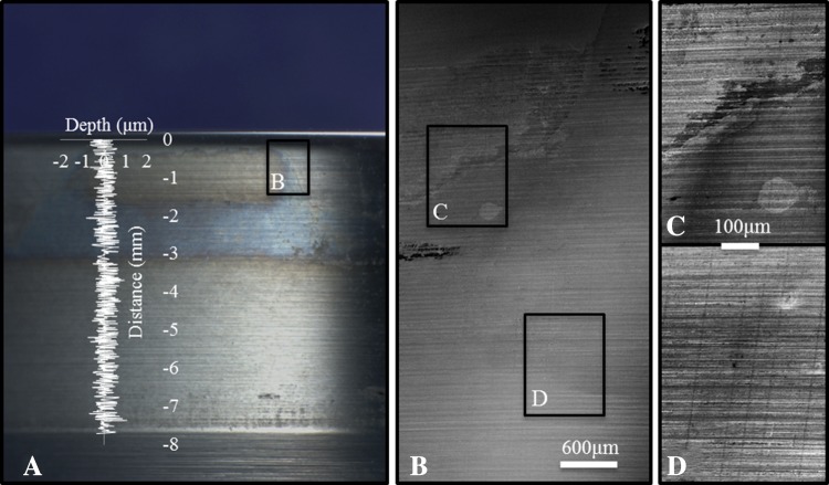
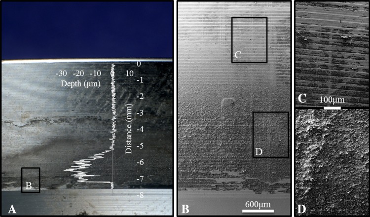
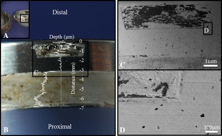
Visual inspection of some components showed apparent visual evidence of fretting and/or corrosion damage on the liner backside surface (Fig. 7). In one of three liners investigated with scanning electron microscopy, we found that visual analysis of this moderately damaged component (visual score = 3), may misidentify the band of discoloration about the distal end of the taper to represent volumetric material loss (Fig. 8). Scanning electron microscopy of this component showed no distinct change in surface topography, in agreement with the quantitative investigation by the roundness machine where no substantial material loss was identifiable. This scanning electron microscopy analysis showed that apparent visual damage may indicate actual material loss when imaged at high magnification. For visual analysis, we were able to identify undamaged as-manufactured regions, but damaged regions may not have quantifiable material loss. Scanning electron microscopy was able to distinguish between damaged regions and machining marks from high magnification imaging using the secondary electron detector which provides imaging of surface topography.
Fig. 7A–D.
Visual indications of liner damage, which was shown to have quantifiable material loss, can be seen. (A) A visual overview of the taper surface is shown. (B) Scanning electron microscopy, 10 kV, shows topographic changes at low magnification (×25). (C) Machine marks from manufacturing can be clearly seen (×100). (D) There is a distinct change in surface topography in a damaged region (×100). The axial profile (overlay) shows quantitative surface topography along the taper. The fit region was −3.3 to −1.3 mm on the distance axis.
Fig. 8A–D.
Visual indications of liner damage, which did not show quantifiable material loss, are shown. (A) This visual overview of the taper surface shows discoloration and resulted in a visual damage score of three. (B) Scanning electron microscopy, 10 kV, shows relatively consistent topography at low magnification (×25). (C) Machine marks from manufacturing can be seen inside and outside the bands of discoloration (×100). (D) There was no apparent change in surface topography in the discolored region; the vertical lines are from the roundness machine measurements (×100). The axial profile (overlay) shows quantitative surface topography along the taper. The fit region was −3.3 to −1.3 mm on the distance axis.
The roundness machine could be used to identify the as-manufactured surface without scanning electron microscopic imaging of every component owing to the nature of the contact geometry and the known amplitude and wavelength of the machining marks. For this particular implant design the most frequent locations for material loss occurred at the distal part of the liner taper which corresponded to the location of symmetrically spaced antirotation notches in the acetabular shell (incorporated for use with UHMWPE modular liners) and the proximal part of the liner taper surface which appeared to fully engage with the shell (Fig. 2). An as-manufactured region was found between these contact areas, corresponding to the location of a groove in the acetabular shell (also incorporated for the locking mechanism when used with a UHMWPE modular liner). The contact geometry and patterns of material loss of these components was easily seen by overlaying an axial profile on an image of the taper surface (Fig. 9). This analysis showed that if the surface of the taper visually looks pristine and the machining marks are still present, that there is no gross material loss; however, if there appears to be visual evidence of taper damage, this may not correspond to material loss.
Fig. 9A–D.
A severely damaged component shows the contact geometry. (A) The acetabular liner and shell indicate the presence of a noncontact region. (B) Liner taper damage could be identified visually by discoloration and texture. (C) A change in the surface topography could be seen at higher magnification (×15) and (D) evidence of material loss could be identified at ×200 magnification. The axial profile (overlay) shows surface measurement along the taper and agrees with scanning electron microscopy analysis. The fit region was −3.2 to −1.6 mm on the distance axis.
Discussion
Adverse local tissue reactions have been linked to metal debris and/or corrosion products produced by metal implants. The characterization of metal interfaces is necessary to understand the source of material debris that may be released to the body and provide insight into mechanisms behind material loss. Understanding the performance of all metal interfaces will provide clinicians information to compare the risks and benefits of various implant designs and guide clinical decision making. Investigations of taper junctions in THRs have shown a quantifiable volume of material loss in some cases [1, 11, 12, 14]. Visual damage scores reported for modular metal-on-metal acetabular liners suggest that they also may exhibit material loss at this interface, contributing to cumulative volumetric metallic material loss of the device [4]. Our study showed CoCr acetabular liners exhibit quantifiable material loss using a reproducible method.
The study has some limitations. Fundamentally, all retrieval studies have to estimate the as-manufactured shape of the component and use this to estimate the material loss. Owing to device design and quantitative and visual surface investigations, we are confident that the location of the unworn region could be identified correctly and assumed to represent the as-manufactured part geometry. Additionally, the least squares fit line through the unworn region was assumed to represent the entire undamaged taper surface, which is valid only if the as-manufactured taper is a perfect straight line. Analysis of relatively undamaged components indicated this is a valid assumption. In addition, circumferential profiles were not chosen for volumetric calculations partly because they do not readily identify machining marks or types of surface damage. Finally, to reduce the compounding effects of any measurement or calculation error, decisions were made at each step in the procedure to generate a conservative estimate for volumetric material loss. While this is a limited sample size (n = 21) of only one implant design, to our knowledge, it is the largest quantitative investigation of the modular metal acetabular liner taper. These liners represent all metal liners that were received by our program; however patients have the option to retain their devices. Although many of our sites have a high enrollment rate, we currently do not track this. Increased sample sizes may reveal statistically significant relationships between patient and implant factors and material loss. Finally, the method analysis used in our study cannot be directly applied to the acetabular shell.
The Talyrond® 585 roundness machine can be used to reproducibly characterize material loss from the taper surface of acetabular liners, and the precision air spindle and diamond stylus make it an ideal tool for measuring tapered surfaces. Some reported taper measurements [1, 11] have relied on the use of a coordinate measuring machine; however we prefer the submicron (0.25 μm) point spacing and 5 μm diameter diamond tip stylus of the Talyrond®, which allows for simultaneous measurement of topography and form, as opposed to the coordinate measuring machine which generally has point spacings of approximately 100 μm and a ruby stylus tip approximately 2 mm in diameter. Our analysis showed the advantage of rotating the component on the precision spindle and keeping the stylus position fixed, as part rotation should account for any leveling inconsistencies when the data are processed and averaged. Reliability also was achieved through standardization of the length of the least squares fit region. While taper length varied with component size, the fit region was kept to 2 mm in all but one case, where it was reduced to 1.7 mm out of necessity. This reduced the normalized range in variability of the volume calculation to less than 3%. The repeatability analysis validated the choice in number of profiles (n = 144) to give consistent calculated volume loss values (range, 1.2%). All modular liners were measured successfully using this method and no outliers were identified after volumetric calculations. The reliability of this technique to produce consistent measurements within 5% makes it an ideal technique for conservative estimates for volumetric material loss investigations of modular MoM acetabular liners. Additionally, this method could be adapted to analyze other taper interfaces of orthopaedic devices.
To our knowledge, this study is the first to quantify the volume of material lost from the taper surface of CoCr liners at the interface with a titanium acetabular shell. The maximum estimated volumetric material loss of the CoCr liners was 1.7 mm3 corresponding to a maximum wear rate of 1.2 mm3 per year. Volumetric rates of material loss of explanted MoM components have been reported to range from 2.08 mm3 to 70.85 mm3 per year [13], for articulating surfaces, and cumulative volumetric wear of 0.07 mm3 to 3.0 mm3 for the femoral head taper [10]. Our study suggests that the maximum rate of material loss from the backside taper of modular liners may be similar in magnitude to that of head taper junctions and the lower rates reported for bearing surfaces (Table 3).
Table 3.
Context of findings compared with literature
| Investigated locations | Range of volumetric rates of material loss (mm3/year) | Reference | ||
|---|---|---|---|---|
| Interface | Analyzed surface | Minimum | Maximum | |
| Femoral components | Stem/male taper | 0.005 | 0.006 | [1] |
| Stem/male taper | 0.00 | 0.36 | [12] | |
| Head/female taper | 0.00 | 4.29 | [12] | |
| Head/female taper | 0.59 | 4.87 | [1] | |
| Head/female taper | 0.51 | 13.67 | [11] | |
| Bearing surfaces | Combined | 0.13 | 0.443 | [1] |
| Combined | 2.08 | 70.85 | [13] | |
| Liner | 0.04 | 39.62 | [12] | |
| Head | 0.06 | 45.66 | [12] | |
| Acetabular components | Backside liner taper | 0.0 | 1.2 | Current study |
The visual investigations we performed showed the potential for misidentification of regions of volumetric material loss – a type I error, or false positive. No type II errors (false negatives) were observed. Scanning electron microscopy was advantageous for identifying changes in surface topography that may indicate material loss. Bishop et al. [1] also used scanning electron microscopy for taper surface investigation, although they presented no comparison with quantitative analysis. While semiquantitative scoring methods are used to visually assess wear and corrosion damage [3, 5], it may be necessary to use microscopy to accurately identify potential regions of volumetric material loss. We identified two primary regions of contact with the acetabular shell (proximal and distal) using scanning electron microscopy and surface profilometry. The proximal region was found to contribute most to volumetric material loss. Scanning electron microscopy confirmed the presence of changes in surface topography indicative of quantitative material loss in each of the selected components.
We presented a repeatable method for conservatively estimating volumetric material loss from modular MoM acetabular liners using a roundness machine. Although based on a small sample size, a quantifiable amount of material loss (range, 0.0–1.7 mm3) and corresponding rate of material loss (range, 0.0–1.23 mm3/year) were observed. Visual inspection of taper surfaces showed the potential to misidentify discolored regions as regions of material loss; however as-manufactured regions were clearly identified. Scanning electron microscopy can be used to analyze surface topography [1] and may better identify potential regions of material loss that can be quantified by surface profilometry. Future studies also may lead to better understanding of the relation between semiquantitative scoring methods and quantitative analysis. Having complete understanding of implant performance requires identification and quantification of material loss from each component, understanding of the mechanism(s) associated with material loss, and assessing the clinical sequelae, if any, associated with material loss. Our study provides a glimpse into the performance of the mating taper surface of modular CoCr acetabular liners; however, the characterization of bearing surfaces and other modular interfaces is required to fully understand device performance. As adverse local tissue reactions to metal debris concern the orthopaedic community, full characterization of interfaces capable of producing this debris should be done so that device behavior may be better understood.
Footnotes
Institutional funding has been received from the National Institutes of Health (NIAMS) R01 AR47904 (MA, RU, SK, DM, JD, SMK); CeramTec (Plochingen, Germany) (MA, RU, SK, DM, JD, SMK, JP); Stryker Orthopaedics (Mahwah, NJ, USA) (MA, RU, SK, DM, JD, SMK, JP, MM); Zimmer, Inc (Warsaw, IN, USA) (MA, RU, SK, DM, JD, SMK, JP, GK, HC); Celanese (Florence, KY, USA) (MA, RU, SK, DM, JD, SMK); Formae (Paoli, PA, USA) (MA, RU, SK, DM, JD, SMK); Invibio (Lancashire, UK) (MA, RU, SK, DM, JD, SMK); Stelkast (McMurray, PA, USA) (MA, RU, SK, DM, JD, SMK, JP); Aesculap/B.Braun (Center Valley, PA, USA) (MA, RU, SK, DM, JD, SMK); Biomet (Warsaw, IN, USA) (RU, JD, SMK); DePuy Synthes (Warsaw, IN, USA) (RU, JD, SMK, JP); Medtronic (Minneapolis, MN, USA) (RU, JD, SMK); Kyocera Medical (Yodogawa-ku, Osaka, Japan) (RU, JD, SMK); Wright Medical Technology (Arlington, TN, USA) (RU, JD, SMK, MM); DJO (Vista, CA, USA) (RU, JD, SMK, MM); Active Implants (Memphis, TN, USA) (RU, JD, SMK); Smith & Nephew (Memphis, TN, USA) (RU, JD, SMK, JP, HC); Spinal Motion (Mountain View, CA, USA) (RU, JD, SMK); 3 M (Saint Paul, MN, USA) (JP); Joint Active Systems (Effingham, IL, USA) (MM).
One of the authors certifies that he (JP) has received or may receive payments or benefits, during the study period, an amount of USD 10,000 to 100,000 from Smith & Nephew (Memphis, TN, USA) an amount of USD 10,000 to 100,000 from 3 M (Saint Paul, MN, USA), an amount of USD 10,000 to 100,000 from Cadence Pharmaceuticals, Inc (San Diego, CA, USA), an amount of USD 10,000 to 100,000 from CeramTec (Laurens, SC, USA), an amount of USD 10,000 to 100,000 from Pfizer (New York, NY, USA), an amount of USD 10,000 to 100,000 from Salient Surgical (Minneapolis, MN, USA), an amount of USD 10,000 to 100,000 from TissueGene (Rockville, MD, USA), and an amount of USD 10,000 to 100,000 from Zimmer Inc (Warsaw, IN, USA).
One of the authors certifies that he (MM) has received or may receive payments, during the study period, an amount of USD 100,000 to USD 1,000,000 from Stryker Orthopaedics (Mahwah, NJ, USA), an amount of USD 10,000 to USD 100,000 from DJ Orthopaedics (Vista, CA, USA), an amount of USD 10,000 to USD 100,000 from Medical Compression Systems (West Hills, CA, USA), an amount of USD 10,000 to USD 100,000 from Sage Products LLC (Cary, IL, USA), and an amount of USD 10,000 to USD 100,000 from TissueGene (Rockville, MD, USA).
One of the authors certifies that he (GK) has received or may receive payments, during the study period, an amount of USD 10,000 to USD 100,000 from Zimmer, Inc (Warsaw, IN, USA).
One of the authors certifies that he (HC) has received or may receive payments, during the study period, an amount of USD 10,000 to USD 100,000 from Zimmer, Inc (Warsaw, IN, USA), an amount of USD 10,000 to USD 100,000 from Zimmer, Inc (Warsaw, IN, USA), an amount of USD 10,000 to USD 100,000 from Stryker Orthopaedics (Mahwah, NJ, USA), an amount of USD 10,000 to USD 100,000 from Smith & Nephew (Memphis, TN, USA).
All ICMJE Conflict of Interest Forms for authors and Clinical Orthopaedics and Related Research editors and board members are on file with the publication and can be viewed on request.
Each author certifies that his or her institution approved the human protocol for this investigation, that all investigations were conducted in conformity with ethical principles of research, and that informed consent for participation in the study was obtained.
Clinical Orthopaedics and Related Research neither advocates nor endorses the use of any treatment, drug, or device. Readers are encouraged to always seek additional information, including FDA-approval status, of any drug or device prior to clinical use.
This work was performed at the Implant Research Center, Drexel University, Philadelphia, PA, USA.
References
- 1.Bishop N, Witt F, Pourzal R, Fischer A, Rütschi M, Michel M, Morlock M. Wear patterns of taper connections in retrieved large diameter metal-on-metal bearings. J Orthop Res. 2013;31:1116–1122. doi: 10.1002/jor.22326. [DOI] [PubMed] [Google Scholar]
- 2.Dunbar MJ. The proximal modular neck in THA: a bridge too far: affirms. Orthopedics. 2010;33:640. doi: 10.3928/01477447-20100722-30. [DOI] [PubMed] [Google Scholar]
- 3.Goldberg JR, Gilbert JL, Jacobs JJ, Bauer TW, Paprosky W, Leurgans S. A multicenter retrieval study of the taper interfaces of modular hip prostheses. Clin Orthop Relat Res. 2002;401:149–161. doi: 10.1097/00003086-200208000-00018. [DOI] [PubMed] [Google Scholar]
- 4.Higgs GB, Hanzlik JA, MacDonald DW, Gilbert JL, Rimnac CM, Kurtz SM; Implant Research Center Writing Committee. Is increased modularity associated with increased fretting and corrosion damage in metal-on-metal total hip arthroplasty devices?: a retrieval study. J Arthroplasty. 2013;28(8 suppl):2–6. [DOI] [PMC free article] [PubMed]
- 5.Higgs GB, Hanzlik JA, MacDonald DW, Kane WM, Day JS, Klein GR, Parvizi J, Mont MA, Kraay MJ, Martell JM, Gilbert JL, Rimnac CM, Kurtz SM. Method of characterizing fretting and corrosion at the various taper connections of retrieved modular components from metal-on-metal total hip arthroplasty. In: Kurtz SM, Greenwald AS, Mihalko WM, Lemons J, editors. Selected Technical Papers 1560: Metal-on-Metal Total Hip Replacement Devices. West Conshohocken, PA: ASTM International; 2013. pp. 146–156. [Google Scholar]
- 6.Jacobs JJ, Gilbert JL, Urban RM. Current concepts review: corrosion of metal orthopaedic implants. J Bone Joint Surg Am. 1998;80:268–282. doi: 10.2106/00004623-199802000-00015. [DOI] [PubMed] [Google Scholar]
- 7.Krieg A, Speth B, Ochsner P. Backside volumetric change in the polyethylene of uncemented acetabular components. J Bone Joint Surg Br. 2009;91:1037–1043. doi: 10.1302/0301-620X.91B8.21850. [DOI] [PubMed] [Google Scholar]
- 8.Kurtz SM, Ochoa JA, Hovey CB, White CV. Simulation of initial frontside and backside wear rates in a modular acetabular component with multiple screw holes. J Biomech. 1999;32:967–976. doi: 10.1016/S0021-9290(99)00043-3. [DOI] [PubMed] [Google Scholar]
- 9.Kwon YM, Glyn-Jones S, Simpson DJ, Kamali A, McLardy-Smith P, Gill HS, Murray DW. Analysis of wear of retrieved metal-on-metal hip resurfacing implants revised due to pseudotumours. J Bone Joint Surg Br. 2010;92:356–361. doi: 10.1302/0301-620X.92B3.23281. [DOI] [PubMed] [Google Scholar]
- 10.Langton DJ, Jameson SS, Joyce TJ, Gandhi JN, Sidaginamale R, Mereddy P, Lord J, Nargol AV. Accelerating failure rate of the ASR total hip replacement. J Bone Joint Surg Br. 2011;93:1011–1016. doi: 10.1302/0301-620X.93B8.26040. [DOI] [PubMed] [Google Scholar]
- 11.Langton DJ, Sidaginamale R, Lord JK, Nargol AV, Joyce TJ. Taper junction failure in large-diameter metal-on-metal bearings. Bone Joint Res. 2012;1:56–63. doi: 10.1302/2046-3758.14.2000047. [DOI] [PMC free article] [PubMed] [Google Scholar]
- 12.Matthies AK, Racasan R, Bills P, Blunt L, Cro S, Panagiotidou A, Blunn G, Skinner J, Hart AJ. Material loss at the taper junction of retrieved large head metal-on-metal total hip replacements. J Orthop Res. 2013;31:1677–1685. doi: 10.1002/jor.22431. [DOI] [PubMed] [Google Scholar]
- 13.Morlock MM, Bishop N, Zustin J, Hahn M, Rüther W, Amling M. Modes of implant failure after hip resurfacing: morphological and wear analysis of 267 retrieval specimens. J Bone Joint Surg Am. 2008;90(suppl 3):89–95. doi: 10.2106/JBJS.H.00621. [DOI] [PubMed] [Google Scholar]
- 14.Nassif NA, Nawabi DH, Stoner K, Elpers M, Wright T, Padgett DE. Taper design affects failure of large-head metal-on-metal total hip replacements. Clin Orthop Relat Res. 2014;472:564–571. doi: 10.1007/s11999-013-3115-3. [DOI] [PMC free article] [PubMed] [Google Scholar]
- 15.Schmalzried TP, Jasty M, Harris WH. Periprosthetic bone loss in total hip arthroplasty: polyethylene wear debris and the concept of the effective joint space. J Bone Joint Surg Am. 1992;74:849–863. [PubMed] [Google Scholar]
- 16.Young AM, Sychterz CJ, Hopper RH, Jr, Engh CA. Effect of acetabular modularity on polyethylene wear and osteolysis in total hip arthroplasty. J Bone Joint Surg Am. 2002;84:58–63. doi: 10.2106/00004623-200201000-00009. [DOI] [PubMed] [Google Scholar]
- 17.Zahiri CA, Schmalzried TP, Szuszczewicz ES, Amstutz HC. Assessing activity in joint replacement patients. J Arthroplasty. 1998;13:890–895. doi: 10.1016/S0883-5403(98)90195-4. [DOI] [PubMed] [Google Scholar]


