Abstract
Electrical stimulation of nervous tissue is used clinically for the treatment of multiple neurological disorders and experimentally for basic research. With the increase of optical probes to record neuronal activity, simple and user-friendly methods are desired to stimulate neurons and their subcellular compartments for biological experimentation. Here we describe the novel integration of liquid metal electrodes with microfluidic culture platforms to accomplish this goal. We integrated electrode and cell channels into a single poly(dimethylsiloxane) (PDMS) chip, eliminating entirely the need to align electrodes with microchannels. We designed the electrode channels such that the metal can be injected by hand and when the device is non-covalently bound to glass. We demonstrated the biocompatibility of the electrodes for long-term cultures (12 days) using hippocampal neurons. We demonstrated the use of these electrodes to depolarize neurons and recorded neuronal activity using the calcium indicator dye, Fluo-4. We established optimal stimulation parameters that induce neuronal spiking without inducing damage. We showed that the liquid metal electrode evoked larger calcium responses in somata than bath electrodes using the same stimulus parameters. Lastly we demonstrated the use of these liquid metal electrodes to target and depolarize axons. In summary, the integration of liquid metal electrodes with neuronal culture platforms provides a user-friendly and targeted method to stimulate neurons and their subcellular compartments, thus providing a novel tool for future biological investigations.
Introduction
Electrical stimulation of neural tissue is an indispensable technique used both clinically and for basic research. Deep brain stimulation is used to treat essential tremor, Parkinson's disease, chronic pain, depression, and multiple other diseases and disorders.1 Cochlear implants directly stimulate the auditory nerve resulting in improvement for individuals with profound hearing loss.2 Electrical stimulation is also an essential experimental method in neuroscience research to induce synaptic plasticity (e.g., long-term potentiation and long-term depression) and to probe synaptic function; in this case, stimulation is used together with electrophysiological and/or optical recordings to record cellular activity.
While electrophysiological recordings provide better signal and temporal resolution than optical recordings, optical recordings (using dyes or genetic reporters) have the distinct advantage of visualizing localized activity within distal subcellular compartments, including synapses.3 To record electrically from individual neurons, an electrode is usually patched or inserted into the largest part of the neuron, the soma, to record synaptic potentials or current. Unfortunately, the placement of the recording electrode in the soma impedes the acquisition of spatial information such as the localization of activity. There are other advantages for optical recordings, including the ability to monitor activity over longer periods of time and to record a larger number of cells simultaneously. Multiple optical probes have recently been developed, expanding the repertoire of optical tools to visualize activity.4–6
Methods have been developed to locally stimulate neurons and synapses while simultaneously recording activity using optical probes. Techniques have been developed to locally release neurotransmitter while recording calcium dynamics via glutamate uncaging7 and through the use of a microfluidic local perfusion chamber to perfuse glutamate to spatially isolated synaptic regions.8 These methods require the exogenous application of neurotransmitters, bypassing the presynaptic compartment. Another approach that avoids bypassing presynaptic neurotransmitter release is to introduce electrodes directly into neuronal cultures. To achieve subcellular alignment, electrodes can be aligned manually using micromanipulators or microelectrodes patterned onto a bottom substrate can be aligned with a compartmentalized chamber to guide the placement of subcellular process (as has been done for microelectrode recording).9,10 Both of these possibilities require cumbersome preparation and alignment steps for each device.
Here we sought to develop an straightforward method to integrate stimulation electrodes into a microfluidic neuron culture platform11,12 with subcellular accuracy and without the need for manual alignment. To create microelectrodes we used low melting temperature gallium or gallium alloys (referred to here as liquid metal) that can flow into microfluidic channels at room temperature.13 We designed the cell and electrode channels to be integrated into a single PDMS chip, eliminating any alignment steps and reducing the total number of processing steps. We verified the biocompatibility of the resulting platform. Next, we used calcium indicator dyes to record neuronal responses following stimulation, optimized stimulation parameters, and compared these responses to standard bath electrodes. Finally we demonstrated the ability to align electrodes to isolated axons. Together, we demonstrate a new method to stimulate neurons with subcellular resolution, expanding the available toolbox for neuroscience researchers. In addition, the flexibility and biocompatibility of this resulting stimulation platform may hold promise for development of stimulation electrodes for implantable applications.
Results and discussion
Design and fabrication of the neural stimulation platform
We used both pure gallium (m.p. = 29.8 °C) and eutectic gallium indium (EGaIn, 74% gallium, 24.5% indium by weight, m.p. = 15.7 °C)14 to form electrodes within micro-fluidic channels. These liquid metals possess thin metal-oxide “skins” that keep the fluid mechanically stable inside of the channels despite the high surface energies.15 Gallium and EGaIn both have low viscosities at room temperature (approximately twice the viscosity of water) with relatively high conductivities (δ = 3.4 × 10⁴ S cm−1). Unlike mercury, these gallium-based liquid metals have low levels of toxicity16 and are well-suited for forming conductive and mechanically stable structures in microfluidic channels.15,17 In air, gallium forms a passivating oxide layer (i.e., it does not grow thicker with time)18,19 that provides mechanical stability to the liquid metal such that it can maintain its non-spherical structure in the microfluidic channels despite its high surface tension. The metal featuring the thin oxide has been used previously as an electrode for sensitive measurements of charge transport across self-assembled monolayers17 and is therefore likely to be smooth. The metal has also been used for electronic devices based on aqueous hydrogels.20
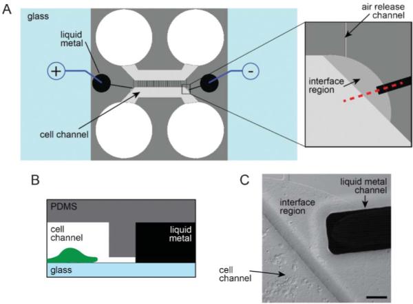
We integrated two electrode channels into the previously described microfluidic platform design11,12 by adding the channels on either side of the cell compartment (Fig. 1). We used soft lithography to fabricate the platform.12 Two SU-8 layers were used to pattern the features. The first layer (~3 μm depth) contained the microgroove features separating the two compartments and an interface region, serving as a flow stop between the electrode and cell channels. This first layer also contains the pattern for an air release channel, preventing air from getting trapped in the device during cell loading. Both the electrode channel and cell compartment were patterned in the second layer (100 μm depth) of SU-8. The cross sectional area of the electrode channel was designed to be 100 μm by 100 μm, which allowed us to fill the liquid metal into the channel by hand using a syringe.13 The amount of pressure needed to flow the liquid metal increases as the size of the channel decreases, thus the liquid metal fills the channel, but stops when it reaches the 3 μm depth interface region. The relatively low pressure needed to fill the electrode channel allowed us to reversibly bond PDMS to glass without needing to covalent bond it, which is advantageous for biological experimentation. These electrode channels were filled with liquid metal via larger source wells that were then connected to the external stimulation source during experimentation. To stimulate neurons, we placed the positive lead into one liquid metal source well and the negative lead into the other (Fig. 1A).
Fig. 1.

Integration of the liquid metal electrodes with the compartmentalized microfluidic platform. (A) Schematic illustration of the assembled platform with a blow-up of the liquid metal and cell channel interface region. (B) Profile view of the red dashed line in A. Features are not to scale. (C) A DIC image of the interface region with neurons plated in the cell channel. Scale bar, 50 μm.
Electrode testing
The liquid metal electrodes have a resistance of approximately 40 ohms, calculated by the dimensions of the electrode and the resistivity of the liquid metal. The majority of resistance in the circuit comes from the region between the two electrode terminals consisting of cell growth media and axonal biomaterial. The total resistance of the circuit is around 2 megaohms. Electrodes were tested under a stimulating AC voltage from a function generator and they remained stable through a relevant range of voltages (0–15 V) and frequencies (1–100 Hz). Higher voltages (>15 V) led to the removal of the stabilizing oxide layer and retraction of the liquid metal. These higher voltages usually coincided with hydrolysis of the cell media, producing gas bubbles which displaced media and axons within the target region.
Biocompatibility testing
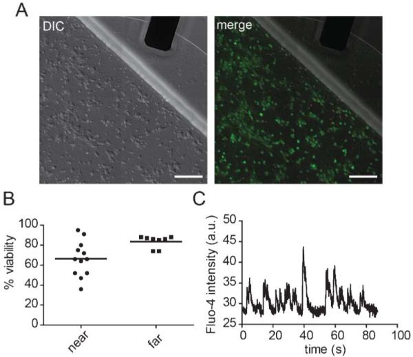
To investigate the compatibility of the liquid metal electrodes with neuronal growth, we cultured hippocampal neurons within the devices for 12 days and then used live/dead stains to determine the percent viability within regions close to the liquid metal electrode compared with >3 mm away from the electrode (Fig. 2). Our data shows that the mean viability is >65% near the metal electrodes and comparable to viability away from the electrodes. To further assess biocompatibility, we recorded spontaneous calcium transients by optically recording neurons plated in the device using the calcium indicator dye, Fluo-4 (Fig. 2C). The presence of spontaneous activity within these neurons demonstrates normal basal activity and parallels spontaneous activity that occurs in vivo.21
Fig. 2.

Biocompatibility of the liquid metal electrodes. (A) DIC image (left) and merged DIC and fluorescent images (right) of neurons labelled with CellTracker AM (green) and propidium iodide (red). Scale bar, 100 μm. (B) Quantification of viability near the interface region (“near”) and away from the electrode (>3 mm away) (“far”). (C) A typical optical recording of spontaneous calcium transients measured from somata within the cell channel containing the liquid metal electrodes. The solid lines = mean.
Neuronal stimulation
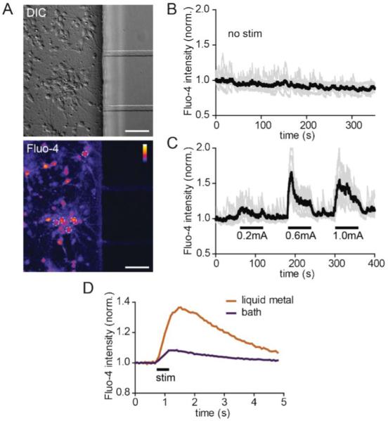
To evaluate and optimize the use of these electrodes, we again used calcium indicator dye to record neuronal activity in response to stimulation (Fig. 3). After culturing neurons for 10 days, we first ran a control experiment without stimulation to get a baseline assessment of spontaneous calcium activity and to determine if there was any laser-induced photo-toxicity during imaging. Photo-toxicity would cause intracellular calcium to rise gradually over the recording time. We did not observe any photo-toxicity as the calcium levels remained stable during the 6 min recording time. We next tested different currents to determine the optimal amperage, keeping the pulse width and frequency constant (200 μs and 10 Hz). We spaced the stimulation periods with rest periods to monitor recovery following stimulation. We found 0.6 mA to be the optimal current based on the rapid rise of calcium and the recovery back to baseline following the end of stimulation. (Note: Equivalent results were obtained using 300 μA and a pulse width of 300 μs—parameters used in subsequent experiments.) Together, these results show that neuronal activity can be induced via the liquid metal electrodes with no evidence of toxicity.
Fig. 3.

Neuronal activity is induced via the liquid metal electrodes. (A) DIC (top) and a static image of fluo-4 labeling (bottom) within the cell channel after stimulation. The white dashed circles show 5 of the 7 soma regions of interest (ROIs) used to generate the graphs in B and C. Color lookup table, “Fire”. Scale bar, 50 μm (B) Baseline fluorescence intensity of individual ROIs (light gray) and average for all ROIs (black) without stimulation. (C) Fluorescent intensity readings of individual and averaged ROIs during alternating stimulation and rest periods. (D) Averaged soma response using liquid metal and bath electrodes. P < 0.001 using two-way ANOVA. Fluo-4 intensities for all graphs are normalized to initial values.
We next compared evoked neuronal responses using liquid metal electrodes to bath electrodes placed within the large wells (Fig. 3D). We used the same stimulation patterns for both electrodes (10 pulses at 20 Hz, 300 μA and 300 μs pulse width). We averaged the neuronal responses for multiple soma ROIs (12 for the liquid metal electrodes, and 7 for the bath electrodes) and over 10 sweeps (15 s each) during the imaging session. The results show that the liquid metal electrodes induced a significantly larger calcium response compared with the bath electrodes using these parameters. These results suggest that the liquid metal electrodes can more effectively stimulate neurons within PDMS-based microfluidic devices than bath electrodes, likely due to the closer proximity of the electrodes to the cells.
Targeted stimulation of axons
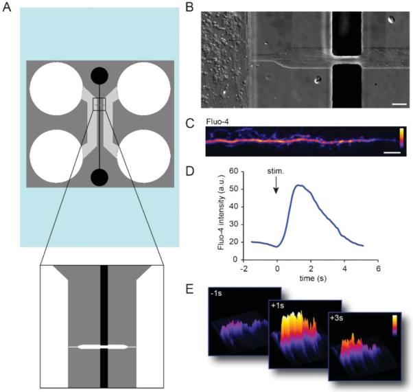
Integrating liquid metal electrodes into microfluidic culture platforms eliminates the need for manual alignment steps between the microchannels and microelectrodes. It also provides a simple way to fabricate electrodes via injection. To demonstrate the ability to target electrodes to subcellular compartments, we designed a different platform to stimulate axons locally. This platform contains both cell channels as before, but only one microgroove connects these two compartments (Fig. 4). Two perpendicular electrode channels are directed towards this axonal channel. The axonal channel broadens where the electrodes connect to facilitate alignment of the second mask layer for the SU-8 master. Fig. 4b shows an example of axonal growth within the axonal channel.
Fig. 4.

Liquid metal electrodes align to an axonal channel to depolarize axons. (A) Schematic of the axon-stim chamber. (B) Neuronal growth within the device. Axons are visible extending into the axonal channel in fluidic contact with the liquid metal electrodes. Scale, 50 μm. (C) An example of an axon labelled with Fluo-4 calcium indicator dye within the axon channel. Color lookup table, “Fire”. Scale bar, 20 μm. (D) Fluo-4 intensity within an axonal ROI over time. (E) Surface intensity maps at different time points for the axonal ROI.
Next we sought to determine if we could locally stimulate axons within this channel (Fig. 4C–E). We again used Fluo-4 to record calcium dynamics in response to the local stimulation. After stimulation we observed a rapid increase locally within the isolated axon that returned back to baseline after stimulation, verifying that we could depolarize axons in a targeted manner.
Experimental
Fabrication of μf devices
Masks to generate the SU-8 master-molds were drafted in AutoCAD (Autodesk Inc.), and printed on 20 000 dpi transparency films (CAD/Art Services Inc., Bandon OR). Master-molds were fabricated in the Chapel Hill Analytical & Nanofabrication Laboratory (CHANL) at UNC as described previously.11,12 SU-8 5 (Microchem) was spun onto a silicon wafer to generate the 3 μm layer SU-8 50 was spun on at a thickness of 100 μm.
Devices were made of PDMS molded onto an SU-8 master, as described previously.11,12 Devices were, sterilized in 70% EtOH and placed onto poly-D-lysine coated glass coverslip substrates as described previously.8 We used 500–550 kDa poly-D-lysine (BD Biosciences) incubating the glass for >6 h at 37 uC.
Electrode preparation
PDMS devices were attached to glass coverslips 0.5–2 h before cell plating. Electrodes were manually filled by adding a drop of liquid eutectic gallium indium (495425-5G, Sigma) or gallium (263265-10G, Sigma) into the electrode wells (~20 μL per chamber) using a syringe with a 20-gauge luer stub adapter and then applying positive pressure with a second 1 cc syringe with no adapter until the channel was filled. Equivalent results were obtained with both compounds, though loading was easier with pure gallium. Approximately 5% of the time, too much pressure was applied to fill the electrode channel and liquid metal spread under the PDMS into the media well or out of the device.
Neuron preparation and plating
E17 rat hippocampal neurons were used for these experiments and prepared as described previously.11 All experiments were performed in compliance with relevant laws and institutional guidelines; all procedures were approved by the UNC Institutional Animal Care and Use Committee. We used 5–10 μL of cell suspension per well at a density of 12 million cells per mL.
Electrical stimulation and recording
Electrical stimulation used to generate Fig. 3A–C was supplied by an ADInstrument's PowerLab 15T (LTS) in current mode. Frequency was 10 Hz and pulse width 200 μs. Leads from the stimulator were clipped to copper wires, which were inserted into the electrode wells. For Fig. 3D we used an ADInstrument 2 Channel Stimulus Generator (STG4002) in current mode using silver chloride coated wires; optimal neuronal response was obtained using a pulse width of 300 μs (lower limit of unit) and 300 μA. For the axonal stimulation in Fig. 4, we used a function generator with the following settings: 2 ms square pulse at 1 V and 10 Hz.
Cell staining
For the viability assay, we used CellTrackerAM (1 μM; Invitrogen) as a live cell dye and propidium iodide (1 : 3000; Invitrogen) to label dead cells. Staining was performed according to Invitrogen protocols. Neural activity was monitored via Fluo-4 NW calcium indicator dye (Invitrogen) as described previously.8 The final solution was diluted 1 : 1 from Invitrogen's protocol.
Microscopy
Images were acquired using a spinning disk confocal imaging system (Yokogawa CSU-X1) configured for an Olympus IX81 zero-drift microscope (Andor Revolution XD system). Excitation was provided by 50 mW 488 nm, 50 mW 561 nm, and 100 mW 640 nm lasers. The following band pass emission filters (Semrock brightline) were used: 525-30 nm (TR-F525-030), 607-36 nm (TR-F607-036), 685-40 nm (TR-F685-040). For Fluo-4 imaging we used a 60x water objective (1.2NA) and 488 nm excitation between 3-5% power. A single slice was imaged with the Olympus ZDC2 continuous focus engaged (to eliminate drift); exposure times equal to or less than 100 ms were used. Andor iQ software was used to acquire images. For the live/dead stain imaging we acquired 2 × 2 montages near the electrode and in the middle of the cell channel (>3 mm away from the electrodes).
Image processing and analysis
Images were processed using NIH ImageJ. To count the live cells, we converted the image to 8 bit depth, thresholded the CellTrackerAM image to identify regions between 23–255 pixel value. We used the analyze particle command to count the regions >74 μm2. To count the dead cells we thresholded the propidium iodide images at 40–255 pixel values and counted particles >3.7 μm2 using the analyze particle command. To calculate the percent viability, we divided the number of live cells by the total number of cells (live plus dead).
For Fluo-4 analysis, 40 μm2 circular ROIs were placed over somata, measured for all frames, and normalized to the initial frame values.
Conclusions
A microfluidic compartmentalized cell culture platform incorporating liquid metal microelectrodes was developed. The electrode material did not adversely affect the growth of neurons within the culture platform, and was able to effectively stimulate target neurons. This device is easily assembled, using readily available materials and without significant set up time. This technique eliminates multiple clean room fabrication steps compared with producing and aligning planar electrodes, thus reduces labor fabrication costs. Liquid metal electrodes effectively stimulate target axons without having to manually align them. The device provides a simple electrical interface to hippocampal neurons, as well as a neatly organized array of small axon populations. The low cost and simple fabrication of these devices means that many samples can be processed in parallel, making it a useful device for biological investigations.
Acknowledgements
We thank Steve Callender (NCSU) for use of the isolated stimulus unit.
References
- 1.Anderson WS, Lenz FA. Nat. Clin. Pract. Neurol. 2006;2:310–320. doi: 10.1038/ncpneuro0193. [DOI] [PubMed] [Google Scholar]
- 2.Shannon RV. Curr. Opin. Neurol. 2012;25:61–66. doi: 10.1097/WCO.0b013e32834ef878. [DOI] [PMC free article] [PubMed] [Google Scholar]
- 3.Staras K, Branco T, Burden JJ, Pozo K, Darcy K, Marra V, Ratnayaka A, Goda Y. Neuron. 2010;66:37–44. doi: 10.1016/j.neuron.2010.03.020. [DOI] [PMC free article] [PubMed] [Google Scholar]
- 4.Li Y, Tsien RW. Nat. Neurosci. 2012;15:1047–1053. doi: 10.1038/nn.3126. [DOI] [PMC free article] [PubMed] [Google Scholar]
- 5.Tian L, Hires SA, Mao T, Huber D, Chiappe ME, Chalasani SH, Petreanu L, Akerboom J, McKinney SA, Schreiter ER, Bargmann CI, Jayaraman V, Svoboda K, Looger LL. Nat. Methods. 2009;6:875–881. doi: 10.1038/nmeth.1398. [DOI] [PMC free article] [PubMed] [Google Scholar]
- 6.Dreosti E, Lagnado L. Exp. Physiol. 2011;96:4–12. doi: 10.1113/expphysiol.2009.051953. [DOI] [PubMed] [Google Scholar]
- 7.Kwon HB, Sabatini BL. Nature. 2011;474:100–104. doi: 10.1038/nature09986. [DOI] [PMC free article] [PubMed] [Google Scholar]
- 8.Taylor AM, Dieterich DC, Ito HT, Kim SA, Schuman EM. Neuron. 2010;66:57–68. doi: 10.1016/j.neuron.2010.03.022. [DOI] [PMC free article] [PubMed] [Google Scholar]
- 9.Ravula SK, McClain MA, Wang MS, Glass JD, Frazier AB. Lab Chip. 2006;6:1530–1536. doi: 10.1039/b612684g. [DOI] [PubMed] [Google Scholar]
- 10.Pan L, Alagapan S, Franca E, Brewer GJ, Wheeler BC. J. Neural Eng. 2011;8:046031. doi: 10.1088/1741-2560/8/4/046031. [DOI] [PMC free article] [PubMed] [Google Scholar]
- 11.Taylor AM, Blurton-Jones M, Rhee SW, Cribbs DH, Cotman CW, Jeon NL. Nat. Methods. 2005;2:599–605. doi: 10.1038/nmeth777. [DOI] [PMC free article] [PubMed] [Google Scholar]
- 12.Taylor AM, Rhee SW, Tu CH, Cribbs DH, Cotman CW, Jeon NL. Langmuir. 2003;19:1551–1556. doi: 10.1021/la026417v. [DOI] [PMC free article] [PubMed] [Google Scholar]
- 13.So JH, Dickey MD. Lab Chip. 2011;11:905–911. doi: 10.1039/c0lc00501k. [DOI] [PubMed] [Google Scholar]
- 14.French SJ, Saunders DJ, Ingle GW. J. Phys. Chem. 1938:42. [Google Scholar]
- 15.Dickey MD, Chiechi RC, Larsen RJ, Weiss EA, Weitz DA, Whitesides GM. Adv. Funct. Mater. 2008;18:1097–1104. [Google Scholar]
- 16.Lide DR. CRC Handbook of Chemistry and Physics. Taylor and Francis; Boca Raton: 2007. [Google Scholar]
- 17.Kim HJ, Son C, Ziaie B. Appl. Phys. Lett. 2008;92:011904. [Google Scholar]
- 18.Regan MJ, Pershan PS, Magnussen OM, Ocko BM, Deutsch M, Berman LE. Phys. Rev. B. 1997;55:15874–15884. doi: 10.1103/physrevb.54.9730. [DOI] [PubMed] [Google Scholar]
- 19.Regan MJ, Tostmann H, Pershan PS, Magnussen OM, DiMasi E, Ocko BM, Deutsch M. Phys. Rev. B. 1997;55:10786–10790. [Google Scholar]
- 20.Koo HJ, So JH, Dickey MD, Velev OD. Adv. Mater. 2011;23:3559–3564. doi: 10.1002/adma.201101257. [DOI] [PubMed] [Google Scholar]
- 21.Yamamoto N, López-Bendito G. Eur. J. Neurosci. 2012;35:1595–1604. doi: 10.1111/j.1460-9568.2012.08101.x. [DOI] [PubMed] [Google Scholar]


