Abstract
We propose a kind of anisotropic planar metasurface, which has capacity to manipulate the orthogonally-polarized electromagnetic waves independently in the reflection mode. The metasurface is composed of orthogonally I-shaped structures and a metal-grounded plane spaced by a dielectric isolator, with the thickness of about 1/15 wavelength. The normally incident linear-polarized waves will be totally reflected by the metal plane, but the reflected phases of x- and y-polarized waves can be controlled independently by the orthogonally I-shaped structures. Based on this principle, we design four functional devices using the anisotropic metasurfaces to realize polarization beam splitting, beam deflection, and linear-to-circular polarization conversion with a deflection angle, respectively. Good performances have been observed from both simulation and measurement results, which show good capacity of the anisotropic metasurfaces to manipulate the x- and y-polarized reflected waves independently.
With the great capacity to manipulate the reflections or refractions of incoming waves, metasurfaces have been attracted more attentions in recent years. The Snell's law provides the refraction and reflection principles when the incoming electromagnetic wave (or light) impinge on the interface of two media with different indexes of refractions. The metasurface has been introduced by applying a series of metallic structures on the interface to generate discontinuous phase shifts, yielding anomalous reflections and refractions, which were explained by the general Snell Law1. Based on the metasurface, many interesting works have been presented, such as photonic spin Hall effect2, polarization-controlled plasmonic coupler3, three-dimensional computer-generated holography image reconstruction4, ultrathin flat lenses5,6, and other applications7,8. In the meantime, the good asymmetric transmission with cross-polarization conversion also can be achieved by ultra-thin chiral metasurface9,10.
All above mentioned transmissive metasurfaces have shown exceptional abilities for controlling the refractions of light, but the transmission efficiency is usually low. The reflective metasurfaces constructed by metallic structures placed on the top of a thin dielectric isolator or substrate with grounded plane on the bottom are the other kinds of metasurfaces, which can manipulate the reflections of incoming waves with high efficiency, reaching nearly 100%. The incoming waves can be totally reflected by the grounded plane on the bottom of the isolator or substrate, but the phases of reflected waves can be modulated by the metasurfaces. By designing gradient metallic structures on the top of isolator, the discontinuous phase shifts on the surface can be achieved to modulate the reflected waves. Earlier invetigations have been conducted on the reflective metasurfaces, such as converting the propagating waves to surface waves11, focusing mirrors12,13, anomalous reflections14,15, and in acoustic application16. However, such reflective metasurfaces are isotropic, which have the same responses for both x- and y-polarized waves, and only a few works based on anisotropic metasurface have been presented17,18,19, which still have limits to control the different polarizations of reflected waves.
In this article, we propose anisotropic reflective metasurfaces, which can manipulate the x- and y-polarized reflected waves independently with high efficiency. The unit cells of the reflective metasurfaces are a series of orthogonally I-shaped structures, which has anisotropic responses for each of orthogonal polarizations (x and y polarizations). The normally incident waves are totally reflected by the metal-grounded plane on the bottom of metasurface, but the reflection phases of both x- and y-polarized waves are controlled independently by changing the dimensions of anisotropic unit cells of metasurface. Based on the proposed anisotropic reflective metasurfaces, four kinds of functional devices are designed, fabricated, and measured for polarization beam splitting, beam deflection, and linear-to-circular polarization conversion with a deflection angle.
Results
Theory and design
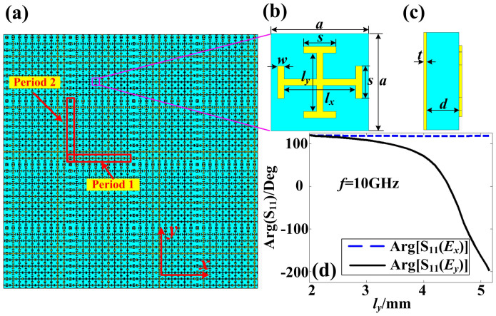
The sketch of the reflective metasurface is demonstrated in Fig. 1(a), in which “period 1” and “period 2” are the periods of the metasurface in two orthogonal directions. We remark that the metasurface can be composed of only one kind of period (“period 1” or “period 2”) or the combination of “period 1” and “period 2” according to different applications. The unit cell in each period is orthogonally I-shaped metallic structures, as shown in Fig. 1(b), which are printed on the top of a dielectric substrate. The dimensions of the structures shown in Fig. 1(b) are a = 6 mm, s = 2 mm, w = 0.4 mm, and lx and ly are changed independently to control the reflection phases of x- and y-polarized electromagnetic waves, respectively. On the bottom of the substrate, there is a metal-grounded plane with thickness of t = 0.018 mm, and the thickness of the substrate is d = 2 mm. The side view of the unit cell is illustrated in Fig. 1(c).
Figure 1. The schematic of birefingent reflective metasurface and its anisotropic unit cell.
(a) The schematic of metasurface, which can be composed of only “period 1” or the combination of both “period 1” and “period 2”. (b) The front view of the anisotropic unit cell, which is composed of two orthogonal I-shaped structures. (c) The side view of the anisotropic unit cell, which shows that the metal-grounded plane and the I-shaped structures are spaced by a dielectric isolator. (d) The phase responses of the anisotropic unit cell, which show that the reflection phase of Ex (see blue dashed line) will not be affected by the length changing of ly but the reflection phase of Ey (see black solid line) is decreased gradually from 130° to −200° when ly is increased from 2 mm to 5 mm.
Figure 1(d) demonstrates the reflection phases at 10 GHz for x- and y-polarized incoming waves with fixed lx = 3 mm and varied ly from 2 mm to 5 mm, from which we observe that the reflection phases of the x-polarized waves will not be affected, but the reflection phases of the y-polarized waves are changed from 130° to −200°. Similarly, if we change the length of lx from 2 mm to 5 mm with fixed ly, then the reflection phases of the x-polarized waves are changed from 130° to −200°, while the reflection phases of the y-polarized waves is not affected. Hence, we conclude that the reflection phases of the x- and y-polarized waves can be controlled independently by using such orthogonal I-shaped structures by changing the lengths of lx and ly, respectively.
Based on the proposed anisotropic reflective metasurface, we present four kinds of functional devices, which have the capacity to manipulate the x- and y-polarized reflected waves independently. As examples, we design the anisotropic metasurfaces in the microwave frequency, which are realized by printed circuit board (PCB) of F4B with the relative permittivity 2.65 and tangent loss 0.001. The metallic orthogonally I-shaped structures and metal-grounded plane are placed on the top and bottom of thin F4B dielectric with the thickness of d = 2 mm. In order to make a clear description of the functions of metasurfaces, a three-dimensional (3D) spherical coordinate system of (r, θ, ϕ) is defined to describe the deflection angle of the reflected waves. The deflection directions of x- and y-polarized waves are defined as (ϕx, θx) and (ϕy, θy), respectively. The relation between the deflection angles of x- and y-polarized waves in 3D space and the reflection phase-delayed distribution on the metasurface can be derived as
 |
The desired u(x,y) can be achieved by the above mentioned gradient metasurface shown in Fig. 1. Meanwhile, the reflected phases of the x- and y-polarized waves are controlled by changing the lengths of lx and ly, respectively. Hence the deflection angles of the reflected x- and y-polarized waves can be manipulated independently according to Eq. (1).
Simulation results
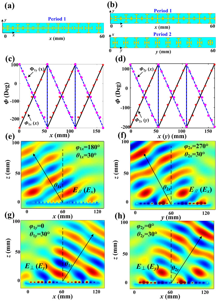
Based on above discussions, we firstly design two kinds of polarization beam splitters (PBSs) at 10 GHz, as shown in Fig. 2. The first PBS is designed to deflect the x- and y-polarized reflected waves to the directions of (ϕ1x = 180°, θ1x = 30°) and (ϕ1y = 0, θ1y = 30°), respectively. The metasurface here is only composed of “period 1”, as illustrated in Fig. 2(a), which is made of ten different unit cells. The lengths of lx and ly of the unit cells in one period are increased and decreased gradually along the +x direction (lx = 2 mm, 3.8 mm, 4.2 mm, 4.4 mm, 4.5 mm, 4.65 mm, 4.75 mm, 4.9 mm, 5.05 mm, 5.15 mm; ly = 5.15 mm, 5.05 mm, 4.9 mm, 4.75 mm, 4.65 mm, 4.5 mm, 4.4 mm, 4.2 mm, 3.8 mm, 2 mm), respectively. According to the relationship between the dimensions of the I-shaped structure and the reflection phase shown in Fig. 1(d), the phase-delayed distributions of three periods along the x direction are demonstrated in Fig. 2(c) (see discrete dots and pentacles), which have good agreements with the calculated Φ1x(x) and Φ1y(x) for (ϕ1x = 180°, θ1x = 30°) and (ϕ1y = 0, θ1y = 30°) (see the blue dashed line and black solid line in Fig. 2(c), respectively. Figures 2(e) and 2(g) are simulated electric-field distributions of x- and y-polarized reflected waves. We clearly observe that the x- and y-polarized reflected waves are deflected to the designed directions of (ϕ1x = 180°, θ1x = 30°) and (ϕ1y = 0, θ1y = 30°).
Figure 2. The designing and simulation results of two PBSs.
(a, c, e, g) The designing and simulation results of the first PBS: (a) The first PBS is only composed of “period 1”. (c) The phase-delayed distributions of three periods along x direction for both x- and y-polarized reflected waves (Φ1x(x) and Φ1y(x)), in which solid black line and dashed blue line are calculation results and discrete pentacles and dots are simulation results of actual structures. (e) The electric-field distributions of x-polarized reflected waves deflected to (ϕ1x = 180°, θ1x = 30°). (g) The electric-field distributions of y-polarized reflected waves deflected to (ϕ1y = 0, θ1y = 30°). (b, d, f, h) The designing and simulation results of the second PBS: (b) The second PBS is composed of both “period 1” and “period 2”. (d) The phase-delayed distributions of three periods of “period 1” along x direction for y-polarized reflected waves (Φ2y(x)) and three periods of “period 2” along y direction for x-polarized reflected waves (Φ2x(y)), in which solid black line and dashed blue line are calculation results and discrete pentacles and dots are simulation results of actual structures. (e) The electric-field distributions of x-polarized reflected waves deflected to (ϕ2x = 270°, θ2x = 30°). (g) The electric-field distributions of y-polarized reflected waves deflected to (ϕ2y = 0, θ2y = 30°).
The second PBS is designed to deflect the x- and y-polarized reflected waves to the directions of (ϕ2x = 270°, θ2x = 30°) and (ϕ2y = 0°, θ2y = 30°), respectively. Both “period 1” and “period 2” are used to construct the metasurface, as shown in Fig. 2(b), in which ly is increased gradually but lx is unchanged along the +x direction in “period 1” (lx = 5.15 mm and ly = 2 mm, 3.8 mm, 4.2 mm, 4.4 mm, 4.5 mm, 4.65 mm, 4.75 mm, 4.9 mm, 5.05 mm, 5.15 mm); while lx is decreased gradually but ly is unchanged along the +y direction in “period 2” (lx = 5.15 mm, 5.05 mm, 4.9 mm, 4.75 mm, 4.65 mm, 4.5 mm, 4.4 mm, 4.2 mm, 3.8 mm, 2 mm and ly = 2 mm). The phase-delayed distributions of three periods for both Φ2x(y) and Φ2y(x) along the +x and +y directions are demonstrated in Fig. 2(d) (see the discrete dots and pentacles), which show good agreements with the calculation results (see the blue dashed line and black solid line). The simulation results of electric-field distributions are given in Figs. 2(f) and 2(h). We notice that the x-polarized reflected waves are deflected to the direction of (ϕ2x = 180°, θ2x = 30°), and the y-polarized reflected waves are deflected to (ϕ2y = 270°, θ2y = 30°). From the simulation results of above two kinds of PBSs, we conclude that the x- and y-polarized reflected waves can be separated and deflected independently in the 3D space, showing good agreements with the theoretical analyses.
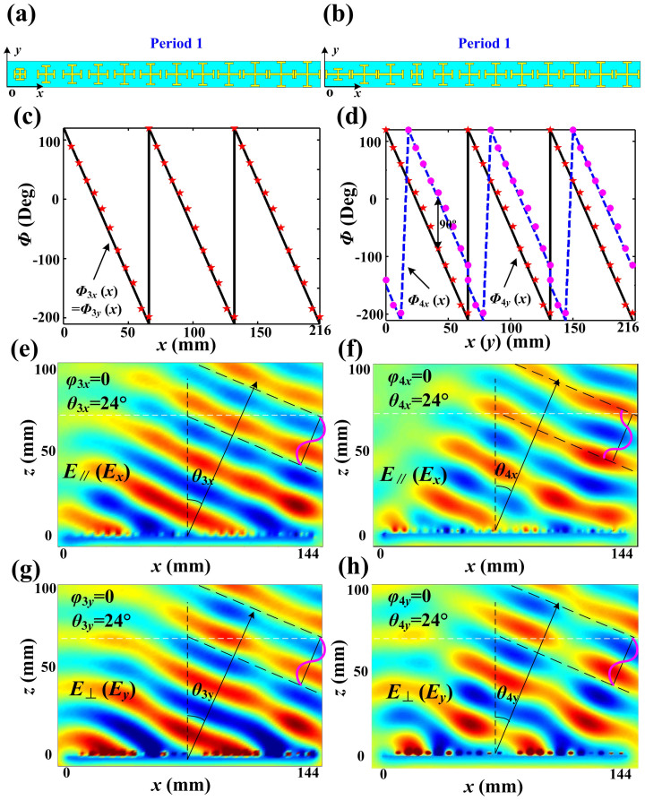
The metasurface can also be designed to deflect the x- and y-polarized reflected waves to the same direction, but the phases of two orthogonal polarizations can be controlled as desired. As example, the third metasurface deflects the reflected beam to a designed angle, which has the capacity to deflect x- and y-polarized reflected waves to the same direction with the same phase. In this case, the metasurface is only composed of “period 1” with 12 unit cells, as shown in Fig. 3(a). lx and ly of the unit cell are equal and increased gradually along the +x direction in “period 1” (lx = ly = 2 mm, 3.7 mm, 4.1 mm, 4.3 mm, 4.45 mm, 4.5 mm, 4.6 mm, 4.75 mm, 4.8 mm, 4.95 mm, 5.1 mm, 5.15 mm). The reflected phase-delayed distributions of three periods for Φ3x(x) and Φ3y(x) along the +x direction are demonstrated in Fig. 3(c), in which the simulation results (see discrete dots) and calculation results (see black solid line) show very good agreements. The simulated electric-field distributions are presented in Figs. 3(e) and 3(g), in which both the x- and y-polarized waves are deflected to the direction of (0, 24°) with the same phase distributions.
Figure 3. The designing and simulationd results of beam deflection and polarization conversion with a deflection angle.
(a, c, e, g) The designing and simulation results of the beam deflection: (a) The third metasurface of beam deflection is only made up of “period 1”. (c) The phase-delayed distributions of three periods along x direction for both x- and y-polarized reflected waves (Φ3x(x) and Φ3y(x)), in which solid black line is calculationd result and discrete pentacles are simulation results of actual structures. (e) The electric-field distributions of x-polarized reflection waves deflected to (ϕ3x = 0, θ3x = 24°). (g) The electric-field distributions of y-polarized reflection waves deflected to (ϕ3y = 0, θ3y = 24°), whose reflection phase is the same with that of x-polarized waves. (b, d, f, h) The designing and the simulation results of the linear-to-circular polarization conversion with a deflection angle: (b) The third metasurface of beam deflection is also only made of “period 1”. (d) The phase-delayed distributions of three periods along x direction for both x- and y-polarized reflection waves (Φ4x(x) and Φ4y(x)), in which solid black line and dashed blue line are calculation results and discrete pentacles and dots are simulation results of actual structures. (f) The electric-field distributions of x-polarized reflection waves deflected to (ϕ4x = 0, θ4x = 24°). (h) The electric-field distributions of y-polarized reflection waves deflected to (ϕ4y = 0, θ4y = 24°), whose reflection phase is 90° ahead compared to y-polarized waves.
The fourth metasurface can convert linear-polarized waves to circular-polarized waves with a deflection angle, which has capacity to deflect both x- and y-polarized reflected waves to the same direction with the phase difference of 90°. Here, the metasurface is only constructed by “period 1” with 12 unit cells, as shown in Fig. 3(b). The lengths of lx and ly of the unit cell are designed differently and gradually changed along the x direction (lx = 4.95 mm, 5.1 mm, 5.15 mm, 2 mm, 3.7 mm, 4.1 mm, 4.3 mm, 4.45 mm, 4.5 mm, 4.6 mm, 4.75 mm, 4.8 mm; ly = 2 mm, 3.7 mm, 4.1 mm, 4.3 mm, 4.45 mm, 4.5 mm, 4.6 mm, 4.75 mm, 4.8 mm, 4.95 mm, 5.1 mm, 5.15 mm) to make sure that the reflected phase difference of each unit cell for the x- and y-polarized waves is 90°. Figure 3(d) illustrates the reflected phase-delayed distributions of three periods for Φ4x(x) and Φ4y(x) along the +x direction. The simulated electric-field distributions are given in Figs. 3(f) and 3(h), from which we observe that both the x- and y-polarized waves are deflected to the same direction (0, 24°), but the phase of the x-polarized waves is 90° ahead to the y-polarized waves. Hence, the linear-polarized incoming waves with normal incidence are reflected by the metasurface to the direction of (0, 24°) with the circular polarization.
Experimental results
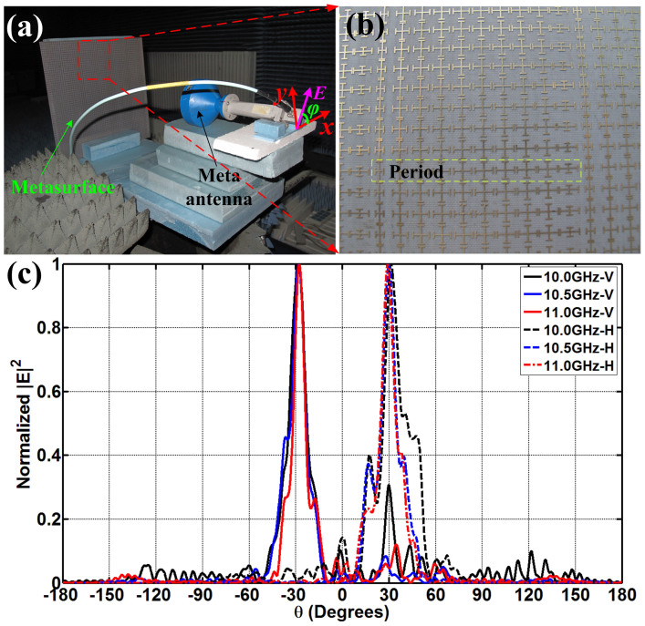
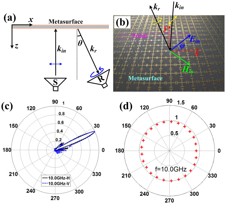
We have fabricated and measured the first PBS and the linear-to-circular polarization converter, whose periodic arrays are demonstrated in Figs. 2(a) and 3(b), respectively. The designed PBS is to separate the x- and y-polarized reflected waves to the directions (ϕ1x = 180°, θ1x = 30°) and (ϕ1y = 0, θ1y = 30°), respectively, whose simulated electric-field distributions are shown in Figs. 2(e) and 2(g). In measurements, the metasurface is placed in an anechoic chamber, and an X-band metamaterial lens antenna20 is used to generate the linearly-polarized planar incident waves (see Fig. 4(a)), which can transform quasi spherical waves to planar waves directly. The metamaterial lens is fed by a rectangular waveguide, which is connected to the Vector Network Analyzer (VNA, Agilent N5230C) via a cable. The rectangular waveguide here only supports the dominant TE10 mode, whose electric-field vectors are vertical to the wide side of the waveguide. We place the X-band metamaterial lens antenna in front of the metasurface and rotate the lens antenna with an ϕ0 = 45° angle, as shown in Fig. 4(a), to make sure the electric-field vector of incident planar waves are polarized along the angle ϕ0 = 45° with respect to the +x axis. Hence the total incident electric-field vector (E) can be decomposed to Ex and Ey components equally.
Figure 4. The measurement of the first PBS.
(a) The experiment setup, in which an X-band metamaterial lens antenna is used as an excitation to generate the linear-polarized incident plane waves. (b) The photograph of fabricated metasurface. (c) The measured far-field patterns, in which the solid lines are vertical (y) polarizations and dashed lines are horizontal (x) polarizations.
The experimental setup shown in Fig. 4(a) is placed on a cloud terrace, which can be rotated from −180° to +180° in the horizontal plane. An X-band standard rectangular horn is fixed in another side of the anechoic chamber as receiver, which can be put with horizontally or vertically polarized to receive the x- and y-polarized reflected waves, respectively. Figure 4(b) depicts the photograph of the metasurface, which is fabricated by F4B with thickness of 2 mm. In Fig. 4(c), the measured far-field patterns demonstrate that the x-polarized reflected waves (see the blue solid line) are deflected to the direction −30° and the y-polarized reflected waves (see the black solid line) are deflected to the direction +30° from 10 GHz to 11 GHz, which have good agreements with the previous numerical simulations.
The linear-to-circular polarization converter can transform the linear-polarized normally incoming waves to circular-polarized reflected waves with deflection angle of (0, 24°). For this purpose, the sketch of experimental setup is demonstrated in Fig. 5(a), in which two antennas are placed in front of the metasurface to transmit the normally incident plane waves and receive the deflected reflection waves. We notice that the aperture of transmitting antenna (X-band metamaterial lens antenna) is fixed to parallel with the metasurface to generate the normally incident plane waves, and the aperture of receiving antenna (standard X-band horn) is placed with angle θ to receive the deflected reflection waves, which can be rotated 360° along its symmetrical axis. The electric vector of linear-polarized incident waves should be polarized along the angle ϕ = 45° to obtain equal Ex and Ey, as shown in Fig. 5(b). Hence the reflected Ex and Ey can be controlled by the anisotropic gradient metasurface independently to make the beams of Ex and Ey deflected to the same direction but have 90° phases difference to achieve circular-polarized reflected waves.
Figure 5. The measurement of the linear-to-circular polarization conversion with a deflection angle.
(a) The sketch of the measurement system. A linear-polarized horn antenna is used as excitation to generate linear-polarized normally incident waves, and another linear-polarized horn antenna is placed having an angle of θ with metasurface as receiver to receive the circular-polarized reflected waves by rotating 360 degrees of the horn. (b) The photograph of the fabricated metasurface. (c) The measured far-field patterns of the reflected waves at 10 GHz, which show that both horizontal (x) and vertical (y) polarized waves are all deflected to θ = 24°. (d) The measured polarization pattern of the reflected waves at 10 GHz.
Before measuring the polarization pattern, we first measured the far-field radiation patterns of the reflected waves to conform the deflecting angle, as shown in Fig. 5(c). We clearly see that both x- and y-polarized reflected waves are deflected to the direction (θ = 24°) at 10 GHz. Then we put the receiving horn in front of the metasurface with angle θ = 24° to receive the reflected waves, and the polarization pattern is achieved by rotating 360° of the linearly-polarized receiving horn, as demonstrated in Fig. 5(d). The axial ratio (AR) of the measured circular polarization is calculated by the definition AR = 20log(b/a) quantitatively, in which a and b represent the lengths of short and long axes of an ellipse, respectively. As a result, AR = 1 dB is achieved, which means that the linearly-polarized normally incident waves are converted to circular-polarized reflected waves with good performance.
Discussion
In this article, we presented a kind of anisotropic reflective metasurface to control different polarizations of reflected waves. The metasurface is a sandwich structure composed of a series of anisotropic unit cells and a metal-grounded plane spaced by a dielectric substrate of F4B, and the thickness of the metasurface is only about 1/15 wavelength. The normally linearly-polarized incident plane waves can be totally reflected by the metasurfce, but the reflected phases of both x- and y-polarized waves are controlled independently by the anisotropic metallic unit cells on the top of measurface. Based on this idea, four kinds of functional metasurfaces have been designed to realize two PBSs, a beam deflection and a linear-to-circular polarization conversion with a deflection angle. The simulation results show good performance as theoretical expectation, and the first PBS and linear-to-circular polarization converter are designed and fabricated, whose measurment results show good agreements with the simulations. Hence, we can conclude that the proposed birefringnet metasurfaces have good capacity to manipulate the x- and y-polarized reflected waves independently with high efficiency.
Author Contributions
H.F.M. designed, performed, interpreted the experiments and wrote manuscript. G.Z.W. generated numerical simulations and interpreted the experiments. G.S.K. interpreted the experiments. T.J.C. supervised and interpreted the design and experiments, and wrote the manuscript.
Acknowledgments
This work was supported in part by the National Science Foundation of China under Grant Nos. 61138001 and 61171024, in part by the Fundamental Research Funds for the Central Universities, in part by the National High Tech (863) Projects under Grant Nos. 2011AA010202 and 2012AA030402, and in part by the 111 Project under Grant No. 111-2-05.
References
- Yu N. et al. Light propagation with phase discontinuities: generalized laws of reflection and refraction. Science 334, 333–337 (2011). [DOI] [PubMed] [Google Scholar]
- Yin X., Ye Z., Rho J., Wang Y. & Zhang X. Photonic spin hall effect at metasurfaes. Science 339, 1405–1407 (2013). [DOI] [PubMed] [Google Scholar]
- Lin J. et al. Polarization-controlled tunable directional coupling of surface plasmon polaritons. Science 340, 331–334 (2013). [DOI] [PubMed] [Google Scholar]
- Huang L. et al. Three-dimensional optical holography using a plasmonic metasurface. Nat. Commun. 3, 2155 (2013). [Google Scholar]
- Aieta F. et al. Aberration-free ultrathin flat lenses and axicons at telecom wavelengths based on plasmonic metasurfaces. Nano Lett. 12, 4932–4936 (2012). [DOI] [PubMed] [Google Scholar]
- Ni X., Ishii S., Kildishev A. V. & Shalaev V. M. Ultra-thin, planar, Babinet-inverted plasmonic metalenses. Light: Sci. Appl. 2, e72 (2013). [Google Scholar]
- Yu N. et al. A broadband, background-free quarter-wave plate based on plasmonic metasurfaces. Nano Lett. 12, 6328–6333 (2012). [DOI] [PubMed] [Google Scholar]
- Kildishev A. V., Boltasseva A. & Shalaev V. M. Planar Photonics with Metasurfaces. Science 339, 1232009–1232009 (2013). [DOI] [PubMed] [Google Scholar]
- Shi J. H. et al. Dual-band asymmetric transmission of linear polarization in bilayered chiral metmaterial. Appl. Phys. Lett. 102, 191905 (2013). [Google Scholar]
- Shi J. H., Ma H. F., Guan C. Y., Wang Z. P. & Cui T. J. Broadband chirality and asymmetric transmission in ultrathin 90°-twisted Babinet-inverted metasurfaces. Phys. Rev. B 89, 165128 (2014). [Google Scholar]
- Sun S. et al. Gradient-index meta-surfaces as a bridge linking propagating waves and surface waves. Nat. Mater. 11, 426–431 (2012). [DOI] [PubMed] [Google Scholar]
- Pors A., Nielsen M. G., Eriksen R. L. & Bozhevolnyi S. I. Broadband focusing flat mirrors based on plasmonic gradient metasurfaces. Nano Lett. 13, 829–834 (2013). [DOI] [PubMed] [Google Scholar]
- Li X. L. et al. Flat metasurfaces to focus electromagnetic waves in reflection geometry. Opt. Lett. 37, 4940–4942 (2012). [DOI] [PubMed] [Google Scholar]
- Sun S. et al. High-efficiency broadband anomalous reflection by gradient metasurfaces. Nano Lett. 12, 6223–6229 (2012). [DOI] [PubMed] [Google Scholar]
- Pu M. et al. Broadband anomalous reflection based on gradient low-Q meta-surface. AIP Adv. 3, 052136 (2013). [Google Scholar]
- Li Y., Liang B., Gu Z., Zou X. & Cheng J. Reflected wavefront manipulation based on ultrathin planar acoustic metasurfaces. Sci. Rep. 3, 2546 (2013). [DOI] [PMC free article] [PubMed] [Google Scholar]
- Pors A., Albrektsen O., Radko I. P. & Bozhevolnyi S. I. Gap plasmon-based metasurfaces for total control of reflected light. Sci. Rep. 3, 2155 (2013). [DOI] [PMC free article] [PubMed] [Google Scholar]
- Farmahini-Farahani M. & Mosallaei H. Birefringent reflectarray metasurface for beam engineering in infrared. Opt. Lett. 38, 462–464 (2013). [DOI] [PubMed] [Google Scholar]
- Pors A. & Bozhevolnyi S. I. Plasmonic metasurfaces for efficient phase control in reflection. Opt. Express 21, 27438–27451 (2013). [DOI] [PubMed] [Google Scholar]
- Chen X., Ma H. F., Zou X. Y., Jiang W. X. & Cui T. J. Three-dimensional broadband and high-directivity lens antenna made of metamaterials. J. Appl. Phys. 110, 044904 (2011). [Google Scholar]


