Abstract
This paper presents a technique for automated intraocular laser surgery using a handheld micromanipulator known as Micron. The novel handheld manipulator enables the automated scanning of a laser probe within a cylinder of 4 mm long and 4 mm in diameter. For the automation, the surface of the retina is reconstructed using a stereomicroscope, and then preplanned targets are placed on the surface. The laser probe is precisely located on the target via visual servoing of the aiming beam, while maintaining a specific distance above the surface. In addition, the system is capable of tracking the surface of the eye in order to compensate for any eye movement introduced during the operation. We compared the performance of the automated scanning using various control thresholds, in order to find the most effective threshold in terms of accuracy and speed. Given the selected threshold, we conducted the handheld operation above a fixed target surface. The average error and execution time are reduced by 63.6% and 28.5%, respectively, compared to the unaided trials. Finally, the automated laser photocoagulation was demonstrated also in an eye phantom, including compensation for the eye movement.
I. Introduction
Laser photocoagulation is a common treatment for retinal diseases such as diabetic retinopathy, retinal detachment, and macular degeneration [1]–[3]. The laser treatment applies patterns of multiple burns in order to impede the growth of new abnormal blood vessels in retinopathy [2], or to seal leaking blood vessels in macular edema [3]. The procedure requires high accuracy for optimal clinical outcomes since inadvertent photocoagulation of a vein can cause vein occlusion. In addition, the procedure is also very tedious for both patient and ophthalmologist [4].
Hence, robotic technology has been introduced into laser photocoagulation in order to improve accuracy and reduce operating time [5]–[7]. For instance, a semiautomated system rapidly delivers up to 50 pulses with shorter pulse duration on predefined spots, using a galvanometric scanner [7]. A fully automated approach was also proposed, based on a hybrid retinal tracking system [5], [6]. For automation, the tracking feature is essential to achieve high accuracy while compensating for the considerable movement of the eye, since the patient is conscious during the treatment and the eye cannot be completely immobilized [8]. The system utilizes digital fundus imaging in real time and thus can perform computer-guided retinal photocoagulation. These systems are now commercially available as PASCAL and Navilas®, but these are designed for treatment through the pupil. Accordingly, the systems are used rather in an outpatient clinic than an operating room [4]. In order to deliver such benefits during intraocular surgery, we have demonstrated semiautomated laser photocoagulation using a handheld micromanipulator [4]. Due to the limited workspace of the 3-DOF prototype of Micron, servoing of the laser probe to the target in [4] was possible only when the probe was located within a few hundred microns of the target,. Thus, the operator is required to deliberately move the instrument for burning other targets. Since the axial range of motion was even smaller than the lateral, the distance of the tool from the surface was manually controlled, relying on the operator’s depth perception. Furthermore, due to the limited number of degrees of freedom in actuation hampers the use of the instrument in real vitreoretinal surgery which requires a fulcrum at the surgical incision point. In addition, tests were performed only on fixed surfaces because the system did not feature tracking of anatomy [4].
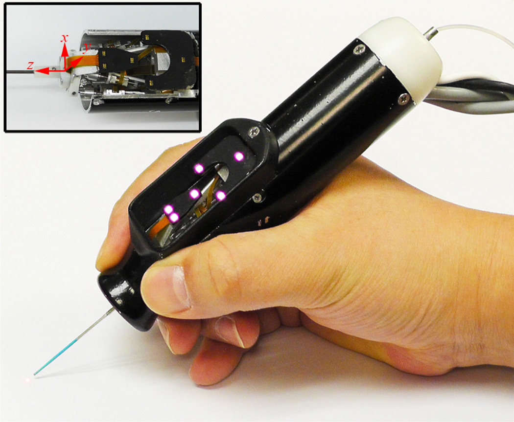
This paper addresses these drawbacks, presenting a system for automated intraocular laser surgery using a new 6-DOF Micron prototype shown in Fig. 1. The new handheld instrument features an enlarged range of motion to enable automated scanning, and its added degrees of freedom accommodate use through a sclerotomy. In this paper, we describe the development of the system and compare its performance with manual execution in an “open-sky” environment. Finally, the technique is demonstrated in an eye phantom, including tracking the movement of the retina.
Figure 1.
6-DOF Handheld micromanipulator integrated with a laser probe.
II. MATERIALS AND METHODS
A. Overall System Setup
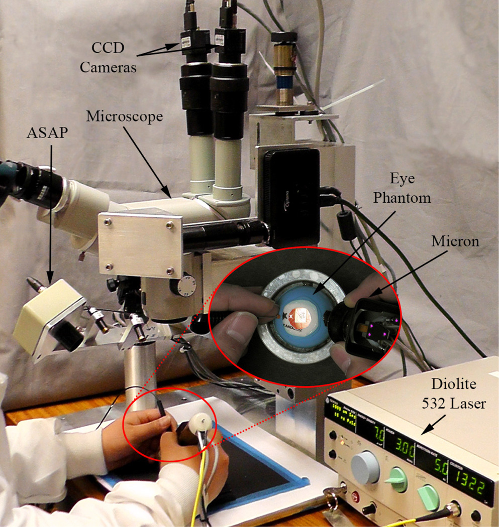
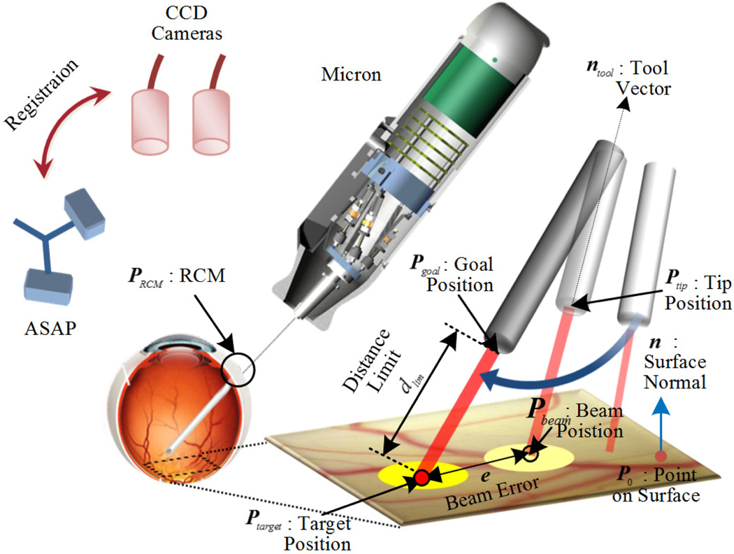
Automated intraocular laser surgery is accomplished by the combination of two systems: the Micron handheld micromanipulator system, and the vision processing system based on the two cameras shown at the top of Fig. 2.
Figure 2.
System setup for automated intraocular laser surgery
The Micron system comprises the handheld manipulator, an optical tracking system, and a real-time controller. The manipulator has been designed to realize the automated scanning of an end-effector, such as for optical coherence tomography or laser photocoagulation during intraocular surgery [9], [10]. The manipulator incorporates a miniature Gough-Stewart platform actuated by six ultrasonic linear motors (SQUIGGLE® SQL-RV-1.8, New Scale Technologies, Inc., USA), as shown in Fig. 1. The manipulator provides 6-DOF motion of the end-effector within a cylinder 4 mm long and 4 mm in diameter when allowing for a remote center of motion (RCM) at the point of entry through the sclera. In order to measure the position and orientation of the tool tip and the handle, the manipulator is equipped with two sets of infrared LEDs: one set on the tool mount and the other on the handle. Consequently, the custom-built optical tracking system (“Apparatus to Sense Accuracy of Position,” or ASAP) provides the position and orientation at a sampling rate of 1 kHz over a 27 cm3 workspace, with less than 10 µm RMS noise [11]. The real-time controller operates in order to reach given goal positions of the tool tip and RCM, via PID control to the motors, while rejecting undesirable hand motion as a disturbance.
The vision system delivers visual feedback to the Micron controller, such as the locations of the laser tip and aiming beam, the 3D surface of a target, and the tracking of the surface. The system consists of a stereomicroscope (Zeiss OPMI®1, Carl Zeiss AG, Germany) with variable magnification (4–25 X), two CCD cameras (Flea®2, Point Grey Research, Richmond, BC, Canada), and a desktop PC. Images are captured at 30 Hz with resolution of 800×600 and sent to the PC for further processing. The images are synchronized with the Micron controller via an external trigger provided by one of the cameras. For the real-time operation, all image processing and computation are completed before new images are captured.
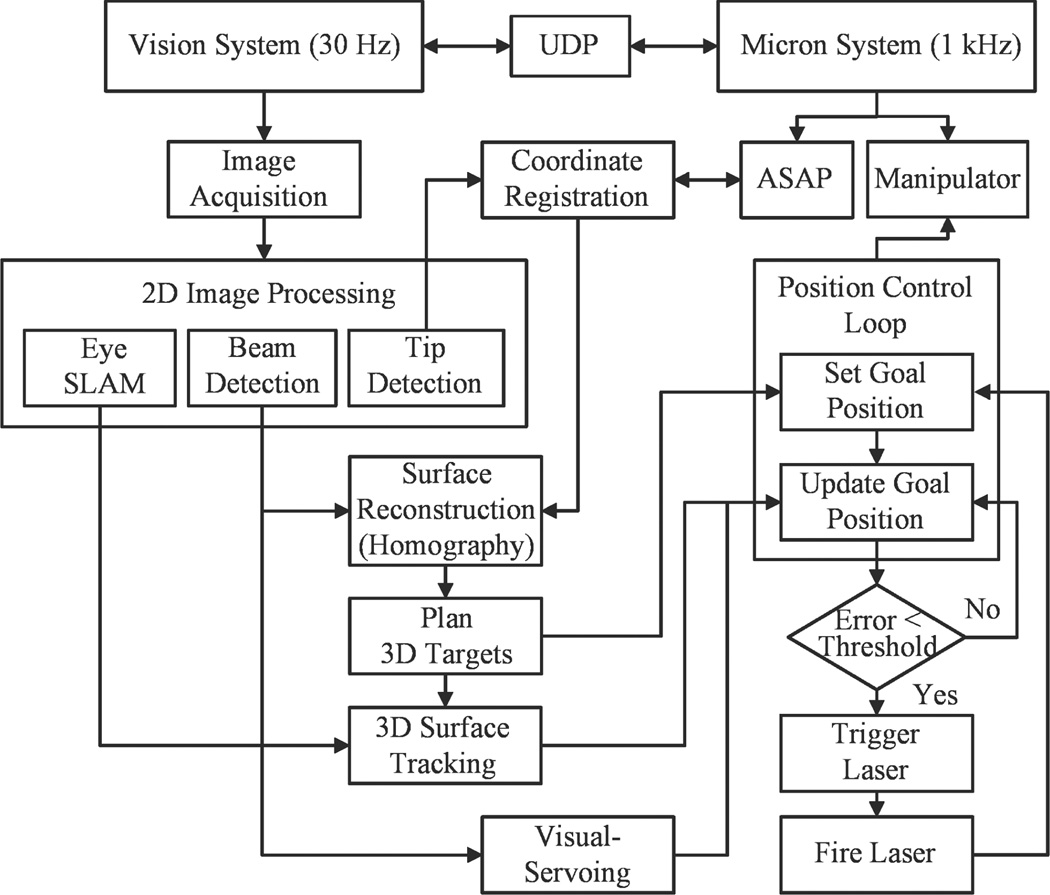
Once a target location for the treatment is defined on a retinal surface with respect to the ASAP coordinate, the corresponding goal position of the laser tip is sent to the Micron controller. During the control, an error between the aiming beam of the laser and the target is minimized by visual servoing. As the aiming beam reaches the target within a certain distance threshold, the laser interfaced with the Micron controller is triggered. Once the laser is fired, the next target is assigned and the procedure is repeated until completion of photocoagulation of all targets. The overall control flow is depicted in Fig. 3.
Figure 3.
Block diagram of the system, showing data and execution flow.
B. System Calibration
1) Coordinate Registration
In order to utilize vision information in control, we register the 2D camera coordinates with the 3D ASAP coordinates in which the control system operates. This follows a general calibration procedure to find a projection matrix in (1), which describes the mapping of 3D points in the world to 2D points in an image. However, a common method relying on multiple views of a planar object would not be feasible in a microsurgical environment. Therefore, we directly match a set of 3D tip positions measured by ASAP with a set of 2D positions detected by the camera, by scanning the tip over the surface. Given the multiple correspondences of the tip position between 2D and 3D, we obtain two projection matrices, ML and MR, for the left and right cameras (1).
| (1) |
where is the tool tip position in homogenous coordinates.
2) Tool offset calibration
The coordinate registration is dependent primarily on the accuracy of the tip position in 3D. However, the principle of the ASAP measurement may lead to an erroneous tip position, since we estimate the tip position from the pose of the LEDs mounted on the moving platform rather than directly measuring the tip. The resulting tip position is computed via rigid body transformation of the platform, taking into account a tool offset Toffset at the tip, typically given by the length of the tool used, as in (2).
| (2) |
where Pwt describes the position and orientation of the moving platform and acts as a homogeneous transformation. Accordingly, any lateral deviations at the tip, such as x- and y-offsets due to misalignment or bending of the tool, affect the estimation of the tool tip pose, resulting in error in the coordinate calibration. As a long slender tool (~60 mm long with less than l mm diameter) is used in intraocular surgery, any small angular displacements of the tool could cause large lateral offsets at the tip.
Hence, we propose a new approach to find the tip offsets Toffset and the projection matrices of the cameras simultaneously using an optimization technique. This idea is inspired by the observation of the projection error of the tool tip in images, given inaccurate tool offsets. The error between the projected and detected tip positions becomes significant under gross change of the orientation of the manipulator while scanning the tool over the surface. Therefore, we model the tip offsets in terms of angular variations θx and θy, and the length of the tool l0 in (3), and we collect data points while varying the orientation of Micron.
| (3) |
The optimization minimizes the squared sum of the projection errors in the left and right camera as in (4).
| (4) |
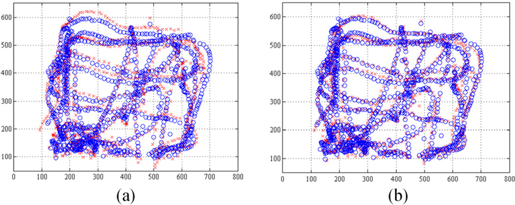
where the ith projection of the tool tip using (1) is denoted by and for the left and right cameras, respectively. The tip positions detected in the corresponding images are indicated as and . We utilize the Matlab™ function ‘fminsearch.m’ referred to unconstrained nonlinear optimization, given the initial length of the tool. Fig.4 shows the projection of the tool tip (red) and the detected tip (blue) on the left image. The projection results for a fixed tool offset along the z-axis and the optimal tool offsets including x- and y-offsets are presented in Fig.4 (a) and (b), respectively. The average projection error decreases from 21.75 to 12.87 pixels by the optimization, compared to the fixed z-axis offset with a length of 56.0 mm. The resulting tip offsets are given as −694, 115, and 54,153 µm for x-, y-, and z-offsets in the Euclidean space; the corresponding angular variations are 0.12° and 0.73° along x and y axes, respectively.
Figure 4.
Tip position collected during the calibration procedure. The blue circle indicates the projection of the 3D ASAP tip position and the red cross the detected tip position in the left image. (a) Before tip-offset calibration. (b) After tip-offset calibration.
C. Surface Reconstruction and Tracking
1) Surface reconstruction
Reconstructing the retinal surface in 3D is necessary for planning burn patterns and regulating the distance of the laser tip from the surface in the automated operation. We adopt a structured light approach to reconstruct the 3D surface instead of the common method of relying on dense stereo matching of feature points in the left and right images. This is because the traditional key point detectors such as SIFT (scale-invariant feature transform) or SURF (speeded up robust features) are prone to fail on such the textureless retina [12]. To provide the structured light, we only need to sweep the Micron back and forth above the surface without a complex coding on the light due to the simplicity of the retinal surface (i.e., no discontinuities, no large spectral reflections, no opacity, and no occlusions). A red aiming beam emitted from the laser probe allows a substantial correspondence on the left and right images. By sweeping Micron, we have a set of 3D points via triangulation of the correspondences in (5) using the projection matrices obtained from (1).
| (5) |
Given the 3D points on the surface, the surface is modeled as a plane rather than a curved surface such as a quadratic or spherical shape, which brings the simplicity in control as well as benefits the surface tracking. In addition, the least-squares type of spherical fitting does work for such as a small area patch, compared to the entire area of the sphere, when containing noisy data points because of the nature of 3D reconstruction. For example, an area patch with 4-mm diameter covers only 2.5% of an entire sphere of the size of the typical human eyeball (25 mm in diameter), which is subject to failure to fit such noisy data. The planar assumption is reasonable for such a small patch, leading to depth error less than 100 µm. This would be comparable to the error on the 3D points obtained from the triangulation. Consequently, the surface is reconstructed as a plane with respect to the ASAP coordinates via least-squares fitting combined with RANSAC algorithm to eliminate noisy data. In addition, the planar homography is also derived in use of the surface tracking.
2) Surface tracking
Tracking the retinal surface is an essential feature to accomplish the fully automated laser photocoagulation because of uncontrolled eye movement during operation [6], [8]. Since vitreoretinal surgeons manipulate the eye with a surgical tool to explore region of interest, and since the patient also may move the eye, the voluntary/involuntary motion is introduced to the eyeball, which causes movement in the microscope view of the retina [12]. To tackle this issue, we have developed an algorithm, called ‘eyeSLAM’, to both map and localize retinal vessels by temporally fusing and registering detected vessels in a sequence of frames [12]. Although eyeSLAM works on such a textureless surface, providing the 2D localization of the vessels at 30 Hz, it is still challenging to apply the algorithm in order to attain a 3D localization result in real time.
Thus we propose a method to extend the 2D localization based on eyeSLAM to 3D, utilizing a planar homography for the surface. Once eyeSLAM provides the vessel map of the left camera image, the map of the right image is derived from the homography transformation H in (6), being assumed as a plane.
| (6) |
Given the vessel maps pvL and pvR of the left and right images, the corresponding 3D map Pv is reconstructed via the triangulation of the maps as in (7).
| (7) |
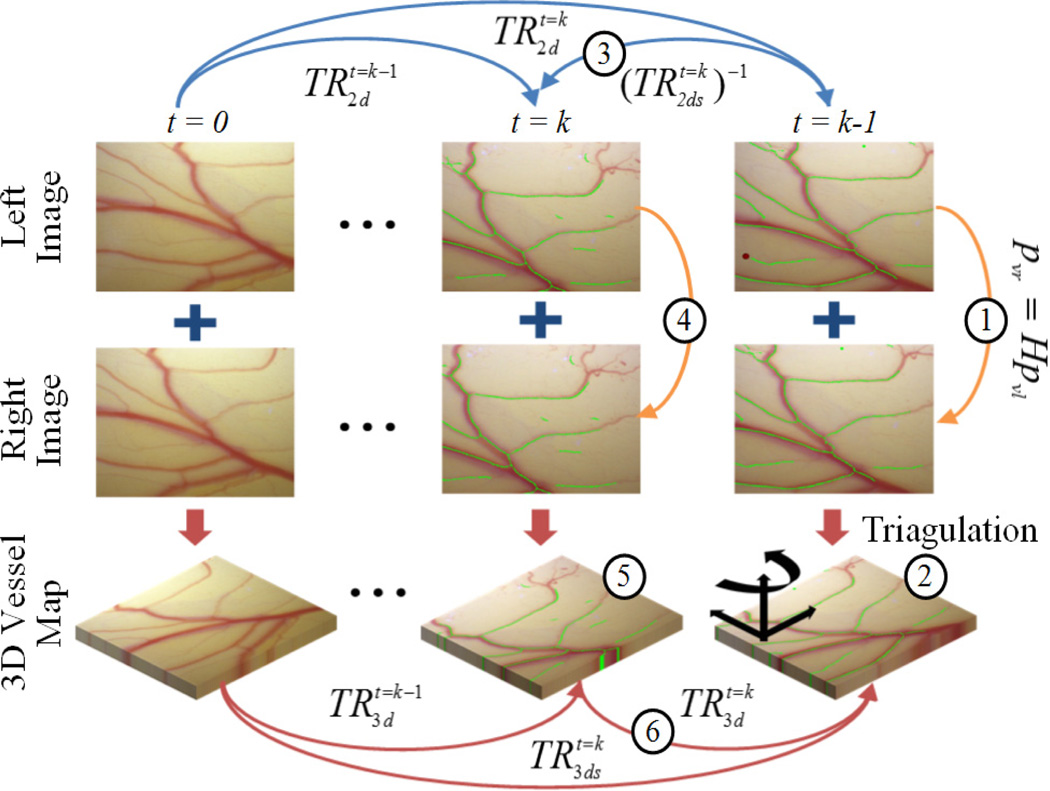
A common method to find a 3D transformation of such an amorphous point cloud is to run iterative closest point (ICP), but it is time-consuming due to the iteration. Hence, we utilize the 2D localization result of the left image to fully recover the 3D localization of the surface instead of applying ICP. Since the 2D localization is provided at each time step, we have a backward transformation from time t = k to t = k-1 using the successive forward transformations and as in (8).
| (8) |
The vessel map on the left image at time t=k is transformed to the map at time t=k-1 via the backward transform
| (9) |
The 3D vessel map at time t=k-1 is also reconstructed using the homography mapping as we reconstruct the 3D vessel map at time t = k. Consequently, a 3D transformation between successive frames is attained from (10) without an effort to match an amorphous 3D point cloud.
| (10) |
The entire 3D transformation with respect to the initial position is acquired by cascading the 3D local transformations (11), which enables tracking of the moving surface.
| (11) |
The overall procedures are illustrated in Fig. 5.
Figure 5.
3D planar surface tracking, utilizing the 2D retinal vessel mapping and localization (eyeSLAM). pattern sizes: 1, 2, 3 mm in diameter.
D. Visual Servoing of Aiming Beam
A goal position of the laser tip Pgoal is defined for aiming at a target, Ptarget, while maintaining a certain distance dlim above the surface along the tip as in (12).
| (12) |
, where ntool is a unit vector of the laser probe and PRCM is the RCM. Given the combination of the goal and RCM positions for the tool in 3D space, only five degrees of freedom are needed for control; rotation along the tool axis is not taken into account during the operation. Accordingly, a specific orientation is only allowed to the laser probe, which is constrained primarily by the location of the RCM. The corresponding parameters and control procedure are also visualized in Fig. 6. However, a small error in the tip position control may induce a large error between the target and the aiming beam on the surface, as the tip becomes far from the surface. Hence, we adopt a PD controller as in (13), in order to compensate for 3D error, e
| (13) |
.
Figure 6.
Visualtization of the control procedure.
Since the PD controller only minimizes the beam error on the plane (i.e., no constraint on vertical motion along the normal), we still need to adjust the goal position, in order to maintain the distance limit. The point on the surface Pplane is defined as the intersection of the ray along the laser probe with the plane, where the plane is described by a surface normal and a point on the surface (n and P0) in (14). Then, the axial distance from the surface dtip is taken into account in the final goal position for keeping the distance limit as in (15).
| (14) |
| (15) |
Both goal positions defined in (12) and (15) are selectively used in control because the aiming beam is not always visible. For instance, we fail to detect the aiming beam at the instant of laser firing, due to saturation on images. Furthermore, the beam is not reliably detected on a dark spot produced by a laser burn. Lastly, the visual servoing is slower than the control using a fixed goal position since the valid vision information is only allowed at 30 Hz; for the rest of the time, not receiving a new image, positions relying on vision system are estimated by a Kalman filter.
III. EXPERIMENTS AND RESULTS
Multiple ring patterns are introduced in our experiments, as a typical arrangement for diabetic macular edema [3]. The targets are spaced 600 µm along the circumferences of multiple circles: 1, 2, and 3 mm in diameter. The total number of the targets planned in a single trial was 32. We used an Iridex Iriderm Diolite 532 Laser with Iridex 29-gauge Endoprobes for laser photocoagulation, triggered by the Micron controller. To burn the targets on a paper slide, the power of the laser was set as 3.0 W with a duration of 20 ms.
A. Control Performance
We investigate the control performance of the system according to various error thresholds to trigger laser firing. This aims to find an acceptable threshold, taking into account accuracy and execution time. The manipulator was firmly affixed to a solid base, in order to eliminate other disturbances such as hand tremor. The tests were repeated for three trials and averaged, given thresholds of 20, 50, and 100 µm, resulting in the total 96 burns. The error was evaluated by the calculation of the 2D distance between the target and actual burn locations. The burn location was found using either fitting an ellipse on a black spot or K-means clustering to distinguish adjoining spots. A green enclosure indicates the fitted ellipse and the blue dot is each center of the k-means clustering in resulting figures.
The average errors are measured in a range of 26–30 µm for all settings. The standard deviations slightly increase from 11 to 14 µm as the threshold become larger. However, the execution time decreases from 31.9 to 21.4 s. Given the results, there is no statistically significant difference between the thresholds, 20 µm and 50 µm, in terms of the average error. However, the difference is noticeable in execution times: decrease from 31.0 to 24.2 s. Although the average error with 100 µm threshold is, of course, larger than the errors with the other lower thresholds, it is still acceptable in laser photocoagulation, compared to the size of the laser spot (200–400 µm). The representative results are presented in Fig. 7 and the analysis details are summarized in Table I.
Figure 7.
Automated laser photocoagulation results according to various control thresholds on a fixed paper slide under a clamped condition: 20 (a), 50 (b), and 100 µm (c). The red circles are overlaid as the indication of pattern sizes: 1, 2, 3 mm in diameter.
TABLE I.
Summary of Experimental Results
| Type | Clamped | Handheld | Eye Phantom |
|||||
|---|---|---|---|---|---|---|---|---|
| Settinga | 20 µm | 50 µm | 100 µm | 0.5 Hz | 1.0 Hz | 50 µm | 100 µm | 100 µm |
| Avg. b | 26 | 26 | 30 | 102 | 104 | 36 | 38 | 65 |
| Std. b | 11 | 13 | 14 | 57 | 55 | 19 | 19 | 32 |
| Max. b | 69 | 73 | 103 | 250 | 265 | 109 | 96 | 175 |
| Timec | 31.9 | 24.2 | 21.4 | 64.0 | 32.0 | 44.0 | 22.9 | 23.9 |
The distance value for a threshold used in the automated trial. The frequency for a repetition rate set in the manual trial.
The unit of error value is in µm.
The unit of time is in s.
B. Handheld Performance
We also evaluated the handheld performance of the automated system, comparing with manual operation, under a board-approved protocol. The user was not a trained surgeon. In manual operation, the laser was fired at a fixed rate, as is typical in laser surgery. The repletion rates were set to be 0.5 and 1.0 Hz, since acceptable results were attainable only with the rate below 1.0 Hz. For the automated trials, the thresholds were set to be 50 and 100 µm from the results of the accuracy tests performed under the clamped setting. We also repeated these tests for three trials and averaged the errors.
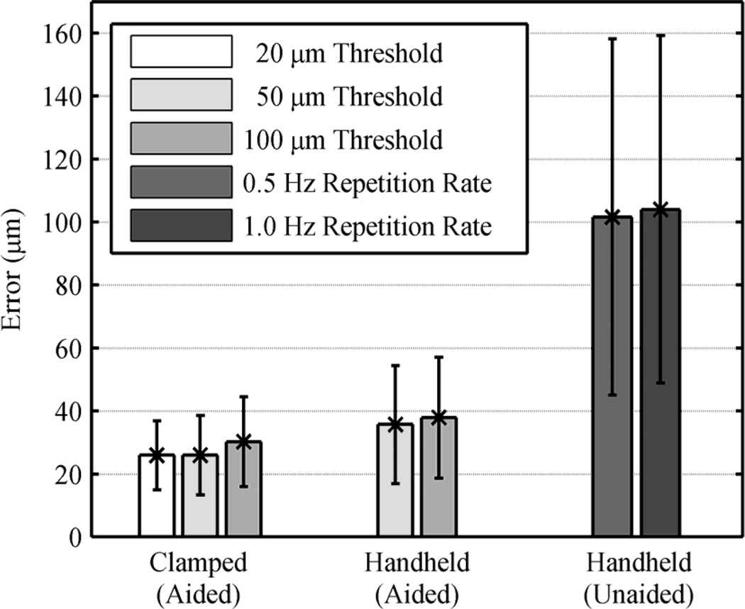
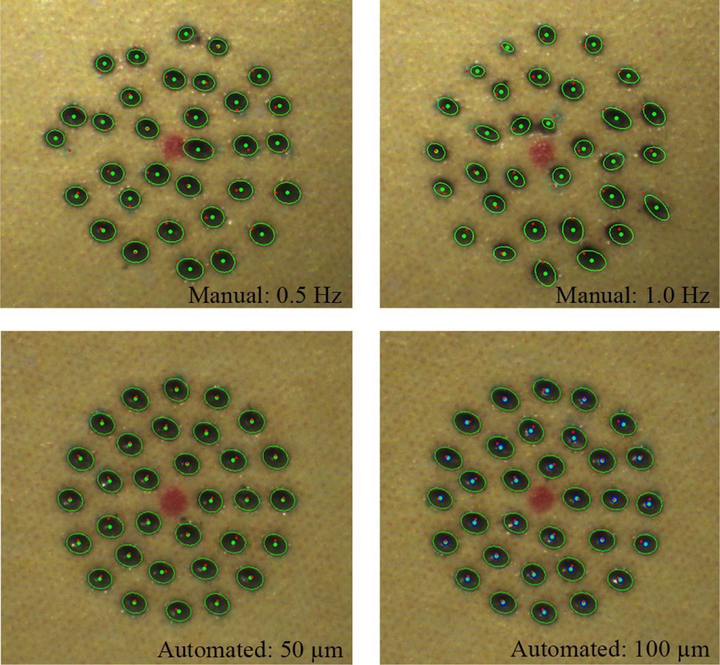
In the automated trials, there is no statistically significant difference in terms of the average error between the thresholds, although it exists in the clamped tests. Noticeably, the execution time drops from 44.0 to 22.9 s with the higher threshold, whereas it was similar under the clamped condition (24.2 and 21.4 s, respectively). This is because hand tremor involved in these tests leads the control system to reset the laser triggering and repeat it, in order to satisfy such a small threshold, which is subject to the increment in execution time. In the manual trials, the average errors are about 100 µm for both 0.5 and 1.0 Hz repetition rates as shown in Fig. 8 (without a statistically significant difference), although the execution time is doubled with the 0.5 Hz repetition rate. Comparing the automated operation (100-µm thresholds) to manual operation (1.0 Hz), the average error is reduced by 63.5% (p =1×10⁻¹²): from 104 to 38 µm. The execution time is also decreased from 32.0 to 22.9 s (p = 2×10⁻⁵). Representative results are presented in Fig. 9 and the overall results are summarized in Table I.
Figure 8.
Average errors for different tasks and settings, with error bars.
Figure 9.
Handheld performance on a fixed paper slide: Automated vs. manual. The top row shows the results of the unaided trials with 0.5 and 1.0 Hz. The bottom pressents the results of the automated trials with 50 and 100 µm control thresholds.
C. Eye Phantom
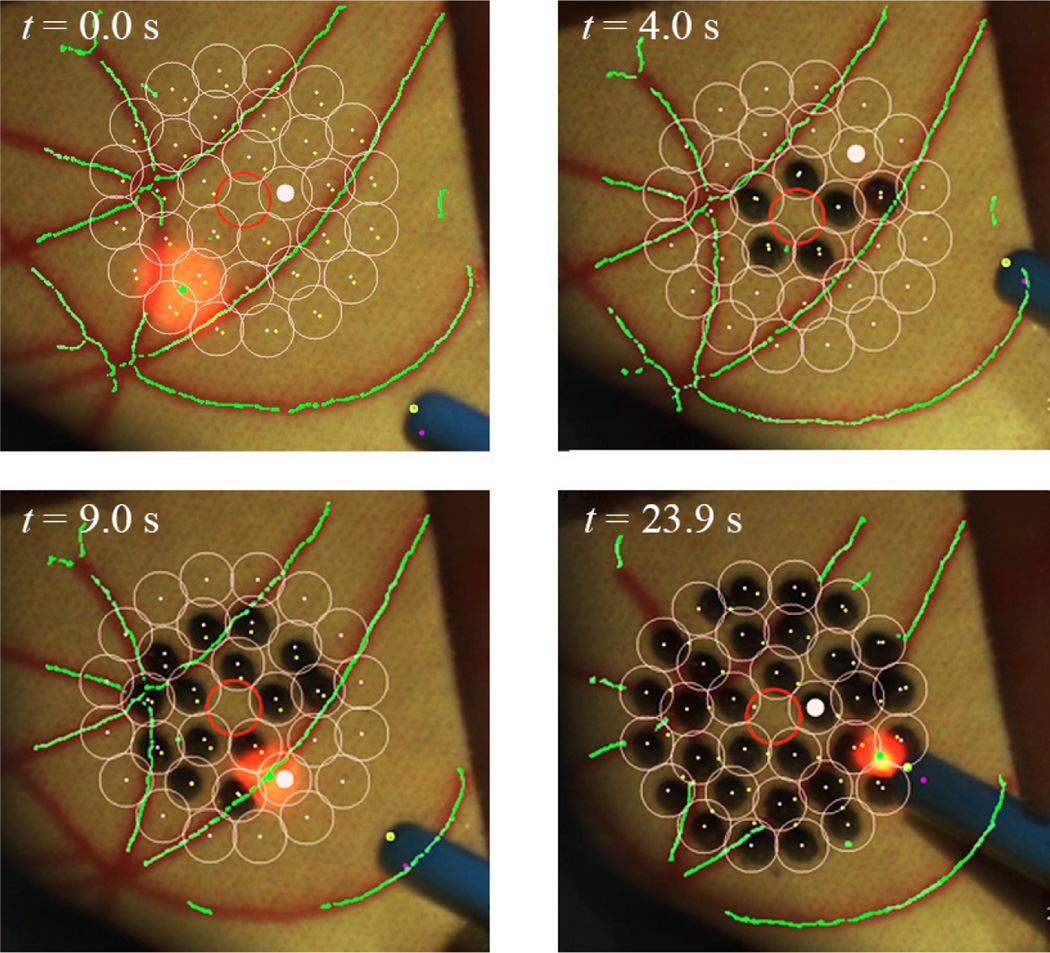
We used an eye phantom by developed by Johns Hopkins University in order to evaluate the performance of the automated system on moving targets. The eye phantom consists of a hollow 25-mm-diameter sphere molded from soft silicone to mimic the natural sclera. The eye phantom was allowed to freely rotate in a ball cup treated with water-based lubricant (K-Y® jelly) as shown in Fig. 2. We attached a piece of a paper slide on the inner surface of the eye phantom to make a burn and analyze the accuracy. Based on the handheld experiments conducted on the fixed targets, we adopted 100 µm as the appropriate threshold for this experiment in terms of accuracy and execution time. To compensate for eye movement, the preplanned targets were tracked during the task. The average error for three trials is 65 µm, which is larger than the result obtained on the fixed surface. Nevertheless, there is no significant increment in the execution time between the trials on the moving and fixed targets. Fig. 10 shows the resulting burns according to different time stamps, while successfully tracking the targets during the operation.
Figure 10.
Demonstation of the automated intraocular laser photocoagulation in an eye phantom. The pink circles indicate the preplanned targets lying on the inner surface of the eye phantom. The green lines represent the artifical vein map as detected by the eyeSLAM algorithm, which tracks the vessels throughout the operation.
IV. DISCUSSION
We demonstrate the automation of intraocular laser surgery using a newly developed 6-DOF handheld micromanipulator. The 4-millimeter range enables the automated scanning of the laser probe, regulating the height of the probe from the retinal surface. The simultaneous calibration method contributes to improving the accuracy of the coordinate registration. In addition, the 3D tracking feature realizes the automated operation in a moving target such as in the eye phantom. Compared to the semiautomated laser surgery using the 3 DOF Micron [4], the accuracy is significantly improved, providing 63.6% of error reduction between the manual operation with 1.0 Hz repetition rate and the automated operation with 100 µm threshold; the semiautomated system showed 22.3% error-reduction. The execution time is also reduced from 1.88 s/pattern to 1.40 s/pattern. Furthermore, the new manipulator allows automated depth control, which was not featured in the semiautomated system due to the limited workspace of the manipulator used, especially along the axis of the tool. This is an important factor for ensuring safety operation and also for reducing the cognitive burden of the surgeon.
The comparative study of the automated surgery in the eye phantom will be followed, by visualizing a virtual target through the microscope for the manual operation [13]. The tracking feature will also be refined to stabilize the tracking result and to filter a noisy vessel map. Given reliable detection and tracking, we will be able to assign an avoidance zone on the surface for preventing inadvertent damage on a critical structure such as the fovea [3]. Further experiments will also be performed on biological tissues ex vivo and in vivo.
Acknowledgments
Research supported by the U. S. National Institutes of Health (grant nos. R01EB000526 and R01EB007969) and the Kwanjeong Educational Foundation.
References
- 1.Kampik A. Laser, intravitreal drug application, and surgery to treat diabetic eye disease. Oman J. Ophthalmol. 2013 Jan;6(Suppl 1):S26–S31. doi: 10.4103/0974-620X.122291. [DOI] [PMC free article] [PubMed] [Google Scholar]
- 2.The Diabetic Retinopathy Study Research Group. Photocoagulation treatment of proliferative diabetic retinopathy: clinical application of Diabetic Retinopathy Study (DRS) findings, DRS Report Number 8. Ophthalmology. 1981 Jul;88(7):583–600. [PubMed] [Google Scholar]
- 3.Bandello F, Lanzetta P, Menchini U. When and how to do a grid laser for diabetic macular edema. Doc. Ophthalmol. 1999 Jan;97(3–4):415–419. doi: 10.1023/a:1002499920673. [DOI] [PubMed] [Google Scholar]
- 4.Becker BC, MacLachlan RA, Lobes LA, Riviere CN. Semiautomated intraocular laser surgery using handheld instruments. Lasers Surg. Med. 2010;42(3):264–273. doi: 10.1002/lsm.20897. [DOI] [PMC free article] [PubMed] [Google Scholar]
- 5.Markow MS, Yang Y, Welch AJ, Rylander HG, Weinberg WS. An automated laser system for eye surgery. IEEE Eng. Med. Biol. Mag. 1989;8:24–29. doi: 10.1109/51.45953. [DOI] [PubMed] [Google Scholar]
- 6.Naess E, Molvik T, Ludwig D, Barrett S, Legowski S, Wright C, de Graaf P. Computer-assisted laser photocoagulation of the retina–a hybrid tracking approach. J. Biomed. Opt. 2002 Apr;7(2):179–89. doi: 10.1117/1.1461831. [DOI] [PubMed] [Google Scholar]
- 7.Blumenkranz MS, Yellachich D, Andersen DANE, Wiltberger MW, Mordaunt D, Marcellino GR, Palanker D. Semiautomated patterned scanning laser for retinal photocoagulation. Retina. 2006 Mar;26(3):370–376. doi: 10.1097/00006982-200603000-00024. [DOI] [PubMed] [Google Scholar]
- 8.Chhablani J, El-Emam S, Kozak I, Barteselli G. A novel navigated laser system brings new efficacy to the treatment of retinovascular disorders. Oman J. Ophthalmol. 2013 Jan;6(1):18. doi: 10.4103/0974-620X.111898. [DOI] [PMC free article] [PubMed] [Google Scholar]
- 9.Yang S, Maclachlan RA, Riviere CN. Manipulator design and operation of a six-degree-of-freedom handheld tremor-canceling microsurgical instrument. IEEE /ASME Trans. Mechatronics. doi: 10.1109/TMECH.2014.2320858. in press. [DOI] [PMC free article] [PubMed] [Google Scholar]
- 10.Yang S, Balicki M, MacLachlan RA, Liu X, Kang JU, Taylor RH, Riviere CN. Optical coherence tomography scanning with a handheld vitreoretinal micromanipulator. Proc. 34th Annu. Int. Conf. IEEE Eng. Med. Biol. Soc. 2012:948–951. doi: 10.1109/EMBC.2012.6346089. [DOI] [PMC free article] [PubMed] [Google Scholar]
- 11.MacLachlan RA, Riviere CN. High-speed microscale optical tracking using digital frequency-domain multiplexing. IEEE Trans. Instrum. Meas. 2009 Jun;58(6):1991–2001. doi: 10.1109/TIM.2008.2006132. [DOI] [PMC free article] [PubMed] [Google Scholar]
- 12.Becker BC, Riviere CN. Real-time retinal vessel mapping and localization for intraocular surgery. Proc. IEEE Int. Conf. Robot. Autom. 2013:5360–5365. doi: 10.1109/ICRA.2013.6631345. [DOI] [PMC free article] [PubMed] [Google Scholar]
- 13.Rodriguez Palma S, Becker BC, Lobes LA, Riviere CN, Diego S. Comparative Evaluation of Monocular Augmented-Reality Display for Surgical Microscopes. Proc. 34th Annu. Int. Conf. IEEE Eng. Med. Biol. Soc. 2012:1409–1412. doi: 10.1109/EMBC.2012.6346203. [DOI] [PMC free article] [PubMed] [Google Scholar]


