Abstract
The availability of thorough system simulations for detailed and accurate performance prediction and optimization of existing and future designs for a new modality such as magnetic particle imaging (MPI) are very important. Our framework aims to simulate a complete MPI system by providing a description of all (drive and receive) coils, permanent magnet configurations, magnetic nanoparticle (MNP) distributions, and characteristics of the signal processing chain. The simulation is performed on a user defined spatial and temporal discrete grid. The magnetization of the MNP is modelled by either the Langevin theory or as ideal particles with infinite steepness and ideal saturation. The magnetic fields are approximated in first order by calculating the Biot-Savart integral. Additionally the coupling constants between the excitation coils (e.g. drive field coils) and the receive coils can be determined. All coils can be described by an XML description language based on primitive geometric shapes. First simulations of a modelled μMPI system are shown. In this regard μMPI refers to a small one dimensional system for samples of a size of a few tens of a cubic millimeter and a spatial resolution of about 200 μm.
Keywords: Magnetic Particle Imaging, MPI, Simulation, High resolution
I. Introduction
MAGNETIC Particle Imaging (MPI) is a fast and sensitive imaging modality to measure the distribution of magnetic nano particles (MNPs) with a high spatial resolution. The first system already offered a submillimeter spatial resolution at an acquisition speed of 45 volumes per second [1]. For performance predictions as well as optimization of existing and future designs it is crucial to have a thorough simulation and reconstruction framework at hand.
Basically, MPI scanners consist of a magnetostatic gradient field, a dynamic drive field for each spatial direction and receive coils, which are sensitive to the magnetization changes in the analyzed MNPs. To suppress the induced drive field signal in the receive chain and retain only the particle signal, analog notch filters are usually used [2]. However, other techniques to suppress the excitation signal such as field cancelation receive coil topologies [3], [4] are feasible and promise a better reconstruction quality since it allows to use the particle response at the excitation frequency for reconstruction, too.
II. MPI Simulation Framework
Our time-domain simulation framework for MPI (TOSIM) is written in C++ and uses OpenMP for parallelization. The simulations are modelled by an XML steering file, which defines the size of the field of view (FOV) (i.e. the volume considered for the calculations), the geometrical arrangement of the field generators as well as the particle distribution. Furthermore, the temporal resolution Δt and period tscan of scanning a particle distribution is defined via the steering file. The sampling frequency of our signal generation is νsample = 1/Δt.
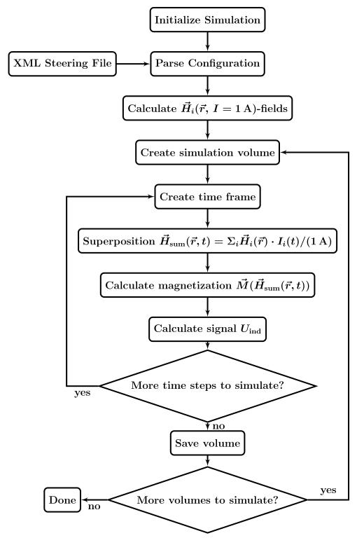
The first step after starting the simulation and parsing the configuration is the calculation of the magnetic fields as well as determing the sensitivity of the receive coils. For each MNP concentration distribution in the FOV a simulation volume is created. A simulation volume consists of Nframes = tscan/Δt frames. For each time ti = i · Δt with 0 ≤ i < Nframes a frame represents the state of the system, which comprises the superposition of all fields at the given point in time, the resulting magnetization in the concentration distribution, and the response of the receive coils. The simulated volumes are stored to an output file. This sequence is illustrated in Fig. 1. The output file structure can be either in the common HDF5 format or a proprietary binary format.
Fig. 1.
Flowchart of the MPI simulation framework.
A. Magnetic Field and Coupling Constants
The present implementation is using the quasi-static approximation of Maxwell’s equations which is neglecting the wave propagation effects [5], [6]. Therefore, the magnetic field of each coil is calculated by using the law of Biot-Savart [7]
| (1) |
with the path of the wire C, the point inside the FOV, and the line element. The intervals between discrete points of the wire are linearly approximated.
All fields are finally added element-wise at each time step t. Besides electromagnets permanent magnets can be used in the simulation as well. The permanent magnets are modelled by using equivalent current loops [8].
In addition, to possibly guide a further optimization of the coil setup, the coupling matrix between all coils is determined by evaluating the integrals
| (2) |
where k and l identify the coil pair, Ck and Cl describe the coil geometries, and are the line elements, and and are points on the wires.
B. Particle Magnetization
After computing the total magnetic field in the FOV the given particle distribution is exposed to the magnetic field. The resulting magnetization is stored for further processing. Two particle models, which are common in the MPI community, are implemented:
Ideal particles are implemented as the Heaviside step function. These particles are assumed to be ideal because the rapid magnetization change results in the best spatial resolution [9].
C. Signal Generation
The induced voltage Uind(t) is calculated by the “Principle of Reciprocity” [11] from the magnetization in the volume V and the sensitivity of the receiving coil at the point at the time t
| (4) |
The equations above hold for a noise free system and thus overestimates the simulated system performance, i.e. the system resolution and sensitivity. Gaussian noise with configurable amplitude can be added to the signal in order to model electronic noise. A simple signal amplification by multiplying the induced voltage with a constant factor is implemented.
Besides, the induced voltage signal can be frequency filtered at this stage of the simulation. This is realized by the FIR filters provided by the GNU Radio project. To avoid aliasing effects the bandwidth of the signal is limited by a low pass filter with a cut-off frequency of 3 νsample/8, a transition bandwidth of νsample/16 and an attenuation of 53 dB. Afterwards the voltage trace can be converted into a “digital” signal by discretizing the signal amplitude with a samplingrate of νsample. The amplitude discretization is peformed with 12-bits, to match with our equipment. Saturation effects are not considered.
D. Image Reconstruction
The reconstruction of MPI images is integrated within this simulation framework, too. To reconstruct an MPI image it is crucial to know the system function, which gives the response of the scanner to a unit particle concentration in the FOV. Analytical approaches to determine the system function exist [9]. However, currently the system function is measured at Nsys points of a regular grid of spatial positions and therefore scales with the resolution and the size of the FOV. Depending on the volume and resolution of the scanner something between ten and several thousand calibration points Nsys have to be measured.
The implemented reconstruction algorithm works on the discrete Fourier transform of the voltage trace . The voltage trace consists of the voltage uj at the discrete time j. Another approach uses the time domain signal for reconstruction and is called X-space MPI [12]. The Fourier space method has the advantage, that the particle signal can be easily extracted, while the X-space MPI has the advantage of a fast reconstruction via deconvolution. The sampled particle concentration distribution is defined as , with the elements ci representing the particle concentration of the i-th voxel.
The system function can be approximated as a transformation matrix, therefore the reconstruction is implemented as a linear equation system, with the system function described by the matrix S. The columns of S contain the discrete Fourier transform of the measurement of each calibration point. Therefore S is a complex matrix of the size . We gain S by simulating the particle response of single voxels in the FOV. Hence for an unknown concentration distribution the equation
| (5) |
has to be solved.
To solve this equation we use the SVD method as described in [5] to determine the pseudoinverse S+ of S. Hence the particle concentration is reconstructed as
| (6) |
This method is equivalent to a least-square fit [13].
S+ is stabilizied by regularization of the singular values σi by weighting them with with the regularization parameter λ. The optimal value of λ has to be determined from a parameter scan. For the implementation of the image reconstruction the linear algebra framework Armadillo [14] has been used.
III. Simulations/Performance Estimates of a μMPI
A. Design
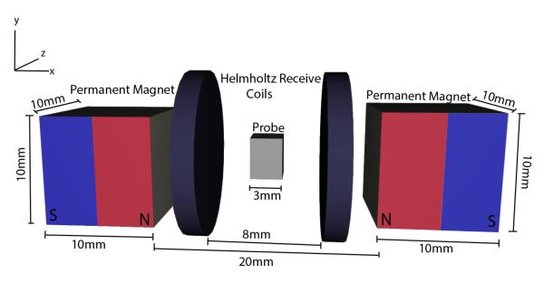
Fig. 2 shows the design of the yet to build scanner. The drive field is created by a Helmholtz coil pair with a radius of 30 mm, a length of 25 mm and 50 windings each. The gradient field of 12 Tm−1 is generated by two permanent magnets with a remanent magnetization of 125 mT mounted with a distance of 17 mm. The receive chain consists of a Helmholtz coil with a radius of 8 mm and ten windings on each coil.
Fig. 2.
Schematic of the μMPI Scanner. Detailed view on the permanent magnets generating the gradient field, the receive coils and the probe volume (FOV). These components are enclosed by drive field coils, which are not shown to achieve a better view on the interior parts.
B. Simulation
To estimate the scanners imaging performance, the previously introduced MPI simulation framework is used. Simulated magnetic fields of the scanner are shown in Fig. 3 with an isotropic resolution of 500 μm.
Fig. 3.
(a) Gradient field along the x-axis generated by two permanent magnets with a remanent magnetization of 125 mT. (b) Magnetic field map through the longitudinal center of the drive field at unit current. The simulated field map in the center fits to the well-known field of a Helmholtz coil. (c) Homogeneous sensitivity along the x-axis of the receive coil in the FOV
The estimated resolution of the scanner is circa 200 μm. Hence the resolution of the simulation grid was chosen to be 40 μm and only covers the designed FOV of 3 mm × 3 mm × 3 mm in the center of the scanner. The time was discretized in 250 ns steps and the probe was scanned for 1025 μs. As the design goal is to sample just a small area, the drive field coil current amplitude was set to 30 A. The drive field current is modulated by a cosine of 25 kHz, which has proven to be a good excitation frequency for Langevin particles and can be realized with audio amplifiers. The system function and the resolution simulations were performed with Langevin particles of a diameter of 30 nm.
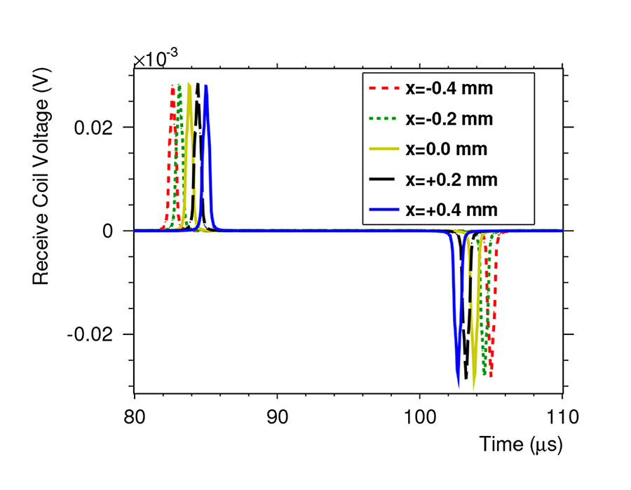
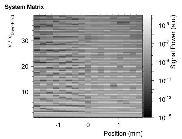
The system function was measured at each grid point of the FOV along the x-Axis in the center of the scanner. The simulated voltage traces in Fig. 4 match the expectations [5, p. 46]. The resulting system matrix without noise in Fourier space is shown in Fig. 5 (magnitude). A position depending structure is clearly recognizable and spatial encoding should be possible.
Fig. 4.
Simulated receive coil responses for different particle positions after applying a low pass filter. The simulated voltage traces matches the behaviour shown in [5, p. 46].
Fig. 5.
Magnitude of the system matrix of the μMPI in Fourier space. It shows that the position of the particle is encoded in the frequency response and therefore a reconstruction of the concentration distribution in the FOV should be feasible.
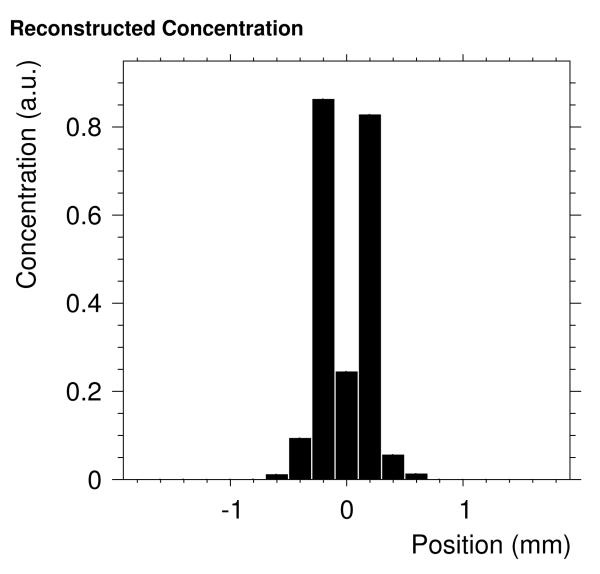
As a next step we determined the spatial resolution of the scanner. Two points are considered as distinguishable if the reconstructed mean concentration between these points is below half of the concentration of the two points. Therefore, the response of the scanner to Langevin particle concentration distributions consisting of two voxels filled with Langevin particles were simulated. The distance between the particles was varied beetween 80 μm and 3.2 mm with an increment of 80 μm. We found that for a spacing of at least 400 μm the two points were distinguishable. The reconstructed concentration distribution for a distance of 400 μm between both points is shown in Fig. 6.
Fig. 6.
Reconstructed concentration of two points of Langevin particles for a noise-free scanner with a distance of 400 μm. The points are clearly distinguishable.
IV. Conclusion
We described the architecture of our time-domain simulation framework for MPI (TOSIM) and the physical principles we use to simulate magnetic fields, induced voltage and particle response. Additionally, we showed the application of our simulation framework to a μMPI scanner topology with a FOV of 3 mm × 3 mm × 3 mm. We derived a spatial resolution of about 400 μm for a noise free system.
Acknowledgment
The authors would like to thank Philips for their financial support of the Ph.D. position of Marcel Straub, for the useful discussions with Bernhard Gleich and for loaning us their first MPI scanner. This work was supported by the European Research Council (ERC Starting Grant 309495: NeoNaNo).
References
- [1].Weizenecker J, Gleich B, Rahmer J, Dahnke H, Borgert J. Three-dimensional real-time in vivo magnetic particle imaging. Physics in Medicine and Biology. 2009 Mar.54(no. 5):L1–L10. doi: 10.1088/0031-9155/54/5/L01. [DOI] [PubMed] [Google Scholar]
- [2].Gleich B, Weizenecker J. Tomographic imaging using the nonlinear response of magnetic particles. Nature. 2005 Jun.435(no. 7046):1214–1217. doi: 10.1038/nature03808. [DOI] [PubMed] [Google Scholar]
- [3].Schulz V, Straub M, Mahlke M, Hubertus S, Lammers T, Kiessling F. A Field Cancelation Signal Extraction Method For Magnetic Particle Imaging. to be published. [DOI] [PMC free article] [PubMed]
- [4].Graeser M, Knopp T, Gruttner M, Sattel TF, Buzug TM. Analog receive signal processing for magnetic particle imaging. Medical Physics. 2013;40(no. 4):042303. doi: 10.1118/1.4794482. [DOI] [PubMed] [Google Scholar]
- [5].Knopp T, Buzug TM. Magnetic Particle Imaging. Springer Berlin Heidelberg; Berlin, Heidelberg: 2012. [Google Scholar]
- [6].Alonso A. A Mathematical Justification of the low-fequency heterogeneous time-harmonic maxwell equations. Mathematical Models and Methods in Applied Sciences. 1999;09(no. 03):475–489. [Google Scholar]
- [7].Jackson JD. Klassische Elektrodynamik. Walter de Gruyter; Berlin, New York: 1983. [Google Scholar]
- [8].Lipfert J, Hao X, Dekker NH. Quantitative modeling and optimization of magnetic tweezers. Biophysical journal. 2009 Jun.96(no. 12):5040–9. doi: 10.1016/j.bpj.2009.03.055. [DOI] [PMC free article] [PubMed] [Google Scholar]
- [9].Rahmer J, Weizenecker J, Gleich B, Borgert J. Signal encoding in magnetic particle imaging: properties of the system function. BMC medical imaging. 2009 Jan.9:4. doi: 10.1186/1471-2342-9-4. [DOI] [PMC free article] [PubMed] [Google Scholar]
- [10].Biederer S, Knopp T, Sattel TF, Lüdtke-Buzug K, Gleich B, Weizenecker J, Borgert J, Buzug TM. Magnetization response spectroscopy of superparamagnetic nanoparticles for magnetic particle imaging. Journal of Physics D: Applied Physics. 2009 Oct.42(no. 20):205007. [Google Scholar]
- [11].Hoult DI, Richards RE. The signal-to-noise ratio of the nuclear magnetic resonance experiment. 1976. Journal of magnetic resonance (San Diego, Calif. : 1997) 2011 Dec.213(no. 2):329–43. doi: 10.1016/j.jmr.2011.09.018. [DOI] [PubMed] [Google Scholar]
- [12].Goodwill PW, Conolly SM. The X-space formulation of the magnetic particle imaging process: 1-D signal, resolution, bandwidth, SNR, SAR, and magnetostimulation. IEEE transactions on medical imaging. 2010 Nov.29(no. 11):1851–9. doi: 10.1109/TMI.2010.2052284. [DOI] [PubMed] [Google Scholar]
- [13].Penrose R, Todd J. a. On best approximate solutions of linear matrix equations. Mathematical Proceedings of the Cambridge Philosophical Society. 2008 Oct.52(no. 01):17. [Google Scholar]
- [14].Sanderson C, Box PO, Lucia S. Armadillo : An Open Source C ++ Linear Algebra Library for Fast Prototyping and Computationally Intensive Experiments Technical Report. NICTA, Tech. Rep. 2011 [Google Scholar]


