Abstract
In nowadays Magnetic Particle Imaging (MPI) signal detection and excitation happens at the same time. This concept, however, leads to strong coupling of the drive (excitation) field (DF) with the receive chain. As the induced DF signal is several orders of magnitude higher, special measures have to be taken to suppress this signal portion within the receive signal to keep the required dynamic range of the subsequent analog to digital conversion in a technically feasible range. For “frequency space MPI” high-order band-stop-filters have been successfully used to remove the DF signals, which unfortunately as well removes the fundamental harmonic components of the signal of the magnetic nanoparticles (MNP). According to the Langevin theory the fundamental harmonic component has a large signal contribution and is important for direct reconstruction of the particle concentration. In order to separate the fundamental harmonic component of the MNP from the induced DF signal, different concepts have been proposed using signal cancelation based on additional DF signals, also in combination with additional filtering.
In this paper, we propose a field-cancelation (FC) concept in which a receive coil (RC) consists of a series connection of a primary coil in combination with an additional cancelation coil. The geometry of the primary coil was chosen to be sensitive for the MNP signal while the cancelation coil was chosen to minimize the overall inductive coupling of the FC-RC with the DF. Sensitivity plots and mutual coupling coefficients were calculated using a thin-wire approximation. A prototype FC-RC was manufactured and effectiveness of the reduction of the mutual inductive coupling (d) was tested in an existing mouse MPI scanner. The difference between simulations (ds=70 dB) and the measurements (dms=55 dB) indicated the feasibility as well as the need for further investigations.
Keywords: Magnetic Particle Imaging, MPI, field cancelation, receive coil
I. Introduction
Magnetic particle imaging (MPI) is known to be a fast and sensitive imaging modality to measure the distribution of magnetic nanoparticles (MNPs) with high spatial resolution [1]. The first system already offered a spatial resolution in the order of 1 mm and a high temporal resolution with about 45 three-dimensional volumes/s [2]. These outstanding system characteristics may make MPI an ideal modality for applications like cell tracking or perfusion imaging.
Besides optimization of the MNPs, a lot of research is centered on improving the sensitivity and efficiency by proposing new drive-field (DF) and focus-field coil topologies, like the field-free-line coils, elliptical coils, or traveling wave coils [3-6]. In combination with harmonic-space MPI the receive chain often contains a high-order and low-loss band-stop filter (BSF) to suppress the drive field signal component in the receive signal and avoid saturation of the amplifier or the analog-to-digital conversion [7]. As a side effect the frequency component of the MNP signal at the drive field frequency, which is according to the Langevin theory the largest harmonic component, is suppressed [8]. Different concepts have been proposed to suppress the DF signal in the receive signal which are using signal cancelation based on additional drive field coil configurations, also in combination with additional filtering [8].
Contrary to [5], this paper will investigate the concept of field cancelation (FC) based on a dedicated receive-coil (RC) design for an existing mouse MPI system [1] without modifying the DF coils. The proposed FC-RC design aims at improving our MPI system with respect to the following aspects:
Reduction of interfering signal pickup from the entire scanner environment and electronics
Reduction of the DF signal in the receive chain without absorbing the fundamental MNP signal components
Enabling of wholistic signal detection of all three MNP signals including components at DF frequency
The paper is structured in the following sections: In the first section we will describe the new concept of the field cancelation receive coil design. Furthermore, an additional compensation method will be introduced that allows a mathematical extraction of the vectorial particle signal from the measurement vector. Results from simulations using MATLAB (The MathWorks, Natick, MA, US) are shown from which the optimal geometry of the cancelation coil can be extracted, minimizing the coupling between drive-field and receive coil. Finally, investigations with a thin-wire RC are presented to verify the principle of the proposed method.
II. The Field Cancelation Receive Coil
A. Basic Concept
The basic idea of the field-cancelation method is well known in the domain of multi-element receive coils for Magnetic Resonance (MR) [9]. In MRI the concept of inductive decoupling is used in order to decouple neighboring local receive-coil elements. In this work, we are going to use inductive decoupling of the drive field coil and the local receive coil by changing the topology of the receive coils. This concept is similar to a gradiometer coil concept [10] which has been proposed by Knopp et al. [7] and Graeser et al. [8] in combination with MPI. In difference to these concepts, our idea proposes to measure an additional compensation voltage which is used for precise extraction of the nanoparticle signal.
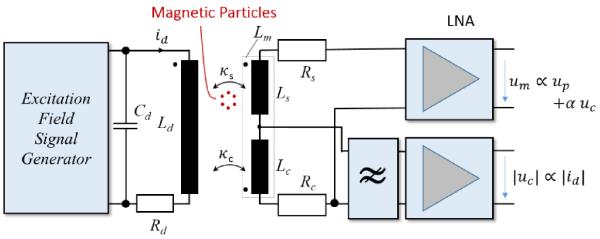
Initially we will consider only one channel for convenience. Later on, we will expand this concept to all three receive and DF coils. Figure 1 shows one signal path, consisting of the DF coil on the left, the receive coils with two Low-Noise Amplifiers (LNA), and the magnetic particles between the drive coil and receive coil, as usually.
Fig. 1. Block diagram of a single channel including the excitation chain and the receive chain of a field cancelation receive coil (FC-RC).
The inductive coupling is determined via the currents through the drive field coil. The inductive coupling between drive field and receive coil is adjusted via geometrical adaptation of the cancelation coil. An additional filter in the cancelation coils might be used to isolate the drive field component from the higher frequency components of the receive signal. Both the compensated and cancelation signals are amplified in a low-noise amplifier.
The drive field coil is driven by the excitation field signal generator. The coil itself consists of a main inductor Ld, with its series resistance Rd and its parasitic capacitance Cd. The FC-RC (Lm) consists of a coil Ls with a high sensitivity for the MNPs and an additional receive coil Lc. Both coils have Ohmical losses, represented by equivalent series resistors Rs and Rc which are the sources of the receive coil noise. The series connection of both inductors, Lm, is connected to a LNA and outputs the measurement voltage um. For the sake of simplification, parasitic components, like capacitive coupling between the windings of the coils are neglected in the receive path in Figure 1. As ideal inductive decoupling is hard to achieve, the measurement voltage um contains a signal which is proportional to the particle concentration (up) and a remaining part that is proportional to the drive field current (id). In addition to the measurement signal, a low-pass-filter might be used in combination with a LNA to sense primarily a signal that is proportional to the drive field current id.
B. Numerical Compensation Method
Figure 1 describes one of three channels that are needed for 3D MPI imaging. Theoretically, the other two drive fields and sensitivity profiles of the receive coils should be orthogonal as one component could be generated via geometrical rotation of the other. Unfortunately this could not be achieved in practice, indicated by inductive mutual coupling between the three drive field components. However, the time signal of all three channels and compensations shall be measured simultaneously and be used in order to extract the vector particle signal . Therefore, we propose to use a correction scheme in frequency domain with a frequency and spatially invariant matrix Ak allowing the computation of the particle vector.
Here is the k-th Fourier component of the time signal and K is the number of considered harmonics. The complex coefficients of the matrix Ak could be obtained from a preceding calibration with an unloaded (no magnetic nanoparticles inside the scanner bore) scanner via the following equation:
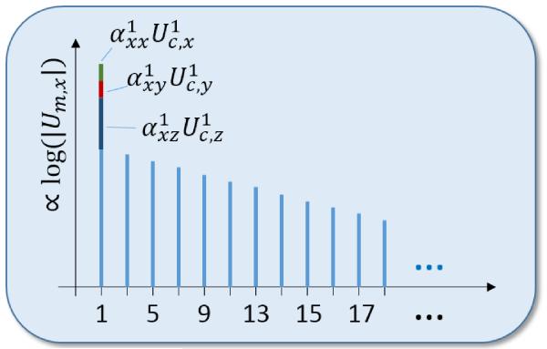
Exemplarily, Figure 2 indicates the targeted correction method for the x channel for the ideal case of absence of high harmonics in case of the empty scanner (k > 1: Ak = 0). The measurement signal contains a significant portion of the drive field components which can, after the estimation of the coefficients , be subtracted, allowing a precise reconstruction of the fundamental harmonic of the MNP signal. We assume that the analog-to-digital conversion (ADC) for has sufficient dynamic range to perform this correction step.
Fig. 2. Exemplarily logarithmic magnitude of the frequency spectrum Um,x of one channel with disturbance of the three drive field components .
The spatial and frequency invariant coefficients need to be measured during a calibration step.
III. Simulation of the Inductive Decoupling
In order to design the geometry of the compensation coil we used a thin-wire approximation to compute the mutual inductance:
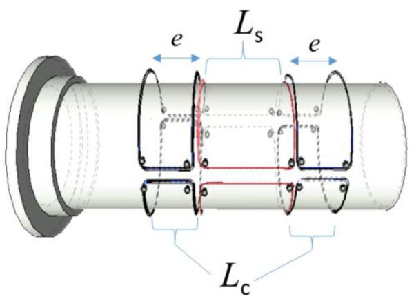
The drive field coil has been approximated via an equivalent thin-wire model. Furthermore, we have chosen a simplified FC-RC topology as given in Figure 3. MATLAB and the simulation environment from [11] have been used to compute this equation.
Fig. 3. Schematic drawing of the field cancelation receive coil (Lm) with the main receive coil in red (Ls) and the surrounding cancelation coils in black (Lc).
The axial extend e of the cancelation coils were chosen to minimize the transfer of magnetic energy between drive and the receive coil.
The FC-RC Lm consists of a centralized rectangular, bent surface coil Ls with a high sensitivity for the MNP response at the MPI scanner’s iso-center and an additional symmetrical receive coil pair Lc. The linear extension e of the compensation coil Lc was chosen to minimize the mutual inductance Mmd between drive field coil Ld and the receive coil Lm.
IV. Results
A. Simulations of the inductive decoupling
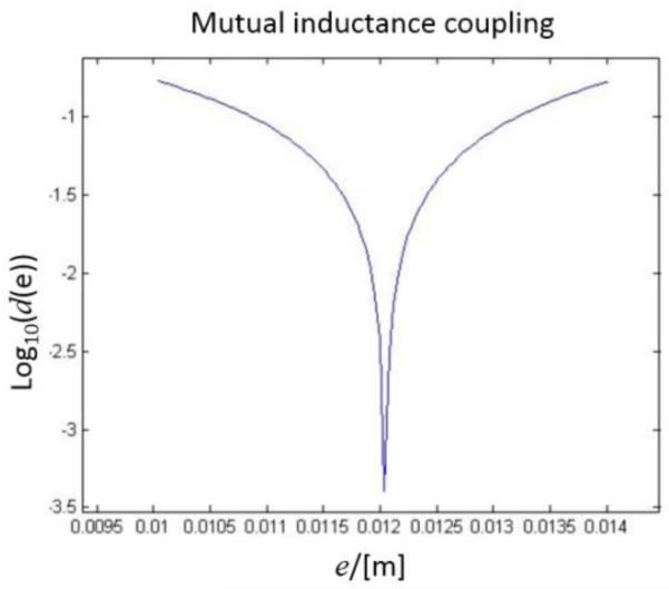
Figure 4 shows the logarithm of the normalized inductive coupling d(e) = Mmd(e)/Mmd(0) as a function of compensation coil extension e, confirmed by the simulation framework of [11] shows good agreement. A clear minimum is indicating the best choice for which both fields (magnetic fields of the drive field coil and receive coil) are almost orthogonal. Intrinsically the mutual coupling between the proposed receive coil and the other two drive field directions should be minor, but will in practice not be negligible.
Fig. 4. Normalized mutual inductive coupling d(e) = Mmd(e)/Mmd(0) as a function of linear extension e calculated using thin-wire approximations.
B. Sensitivity plot of the FC-RC
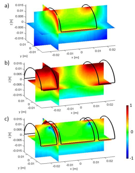
The sensitivity of the FC-RC has been computed for the optimal parameter e. The magnitude of the main receive coil (a), cancelation coil (b), and FC-RC (c) normalized on the origin is plotted in a logarithmic scale on the three orthogonal planes in Figure 5. The ratio of the magnitudes of the coil sensitivities at isocenter of the receive coil (Fig.5-a) and the FC-RC (Fig. 5-c) is 1.04, indicating a slightly higher sensitivity of the FC-RC.
Fig. 5. Iso-plane plots (log10-scale) of the magnitude of the normalized coil sensitivity for a): receive coil (Ls), b): cancelation coil (Lc), and c): the FC-RC (Lm).
Each coil has a vectorial sensitivity defined by the magnetic flux density normalized on the wire current I. In a) and b) normalization has been done to the isocenter values, while in graph c) normalization has been done to the magnitude of the coil sensitivity of a) at iso-center. For b) and c) the x-extension e corresponds to the optimal extension given by the minimum of Figure 4.
C. Measurements of the decoupling using a thin-wire RC
Finally a 3D printed coil carrier has been equipped with a thin-wire (single copper wire, diameter 40 μm, two loops) FC-RC, see Figure 6. The thin wire realization was used to study the decoupling performance. Slight deviation to the geometry used in the simulations were necessary (trapezoidal instead of right-angled cancelation coils) to achieve a decoupling of about 55dB. This deviation might be caused by the simplified single loop approximation of the drive field coil.
Fig. 6. Thin-wire model to explore the field cancelation principle (a) in our mouse MPI system (b).

A reduction of about 55dB was achieved with this coil setup with respect to the signal that was induced in the center coil.
V. Discussion and Outlook
The detection of the MPI signal component at the drive field frequencies promises higher SNR, improved sensitivity, and better quantification of the particle concentration [5]. Therefore, we expect that the proposed FC-RC approach may have an advantage over the traditionally used high-order band-stop-filters, e.g. as used in [1]. As the proposed coil topology leads intrinsically to a quadrupole behavior of the sensitivity pattern, reduced electromagnetic interactions with the environment, like with the shielding box and stray fields from the entire MPI gantry, are of high advantage. This is in particular of interest for the higher parasitic frequency components of the environment. On the other hand, the noise of the receive coils will be increased by increasing the noise resistance of the FC-RC (Lm) compared to the sense coil (Ls). If we neglect the small gain of the coil sensitivity of the FC-RC, the increase of the coil noise could be approximated by , which indicates that the resistor Rc from the compensation coil should be as small as possible compared to Rs. The initial results indicate that substantial suppression (55dB) of the drive field was easily achieved. Nevertheless, compared to the suppression of the band stop filter in our small MPI system [1] of about 80dB, one additional order of magnitude is still required. Further improvements of the decoupling efficiency via additional passive or active lumped elements are therefore needed. In [12] it has been pointed out that for 3D MPI even one receive channel is sufficient but at the cost of SNR. Therefore the presented concept was enlarged to more than one receive channel. In order to avoid coupling between the three individual receive channels, high input impedance of the LNAs is mandatory. The concept of using an additional LNA to measure the cancelation field was introduced to measure directly the exciting magnetic field in amplitude and phase. Motivation for this additional channel was to obtain a signal that is proportional to the drive field current id which is independent of drifts of the parasitic Rd and Cd in the excitation path.
The complex matrix Ak was introduced to allow compensating for amplitude and phase shifts and could thus also compensate for linear parasitic distortion or coupling between the send and the receive system at the drive field frequencies. Nevertheless, alternative methods will be investigated to reduce the amount of receive channels. Finally, investigations are still needed whether the promised gain in SNR might be depleted by the additional noise being introduced by the ohmic losses of the compensation coil windings. Therefore the topology of the receive coil is highly critical.
VI. Conclusion & Outlook
A new field cancelation receive coil method has been presented. The new RC design aims at wholistic detection of the response from magnetic nanoparticles supporting harmonic-space and x-space MPI [13]. The coil design uses an inductively compensated receive channel with a drive field pickup for numerical extraction of the particle signal. A correction method has been introduced that extracts a frequency and space invariant compensation matrix from a calibration scan. First simulation results have been shown and decoupling coefficients without numerical corrections of 55 dB have been achieved. The proposed FC-RC approach has the potential to increase the SNR of the entire MPI acquisition. In future work improvements regarding the noise performance of the FC-RC by using Litz wires and the physical limitation of the field cancelation will be explored in detail.
Acknowledgment
The authors would like to thank Philips for their financial support and for providing us with the mouse MPI system [1]. This work was supported by the European Research Council (ERC Starting Grant 309495: NeoNaNo)
References
- [1].Gleich B, Weizenecker J. Tomographic imaging using the nonlinear response of magnetic particles. Nature. Jun 2005;435(7046):1214–7. doi: 10.1038/nature03808. [DOI] [PubMed] [Google Scholar]
- [2].Weizenecker J, Gleich B, Rahmer J, Dahnke H, Borgert J. Three-dimensional real-time in vivo magnetic particle imaging. Phys. Med. Biol. 2009 Mar;54(5):L1–L10. doi: 10.1088/0031-9155/54/5/L01. [DOI] [PubMed] [Google Scholar]
- [3].Weizenecker J, Gleich B, Borgert J. Magnetic particle imaging using a field free line. J. Phys. D. Appl. Phys. 2008 May;41(10):105009. [Google Scholar]
- [4].Vogel P, Rückert MA, Kullmann WH, Jakob PM, Behr VC. Slice Scanning Mode For Traveling Wave MPI. International Workshop on MPI. 2013;435(7046):796510. [Google Scholar]
- [5].Goodwill PW, Konkle JJ, Zheng B, Saritas EU, Conolly SM. Projection x-space magnetic particle imaging. IEEE Trans. Med. Imaging. 2012 May;31(5):1076–85. doi: 10.1109/TMI.2012.2185247. [DOI] [PMC free article] [PubMed] [Google Scholar]
- [6].Kaethner, et al. On the way to a patient table integrated scanner system in magnetic particle imaging. Proc. SPIE 9038, Medical Imaging 2014. 2014 Mar;903816 doi:10.1117/12.2042765. [Google Scholar]
- [7].Knopp T, Buzug TM. Magnetic Particle Imaging. 1st ed Springer-Verlag; Berlin Heidelberg: 2012. pp. 1–204. [Google Scholar]
- [8].Graeser M, Knopp T, Grüttner M, Sattel TF, Buzug TM. Analog receive signal processing for magnetic particle imaging. Med. Phys. 2013;40(4):042303. doi: 10.1118/1.4794482. [DOI] [PubMed] [Google Scholar]
- [9].Roemer PB, Edelstein W a, Hayes CE, Souza S, Mueller The NMR phased array. Magn. Reson. Med. 16:192–225. doi: 10.1002/mrm.1910160203. [DOI] [PubMed] [Google Scholar]
- [10].Karp P, Duret D. Unidirectional magnetic gradiometers. J. Appl. Phys. 1980;51:1267–1273. [Google Scholar]
- [11].Straub M, Kiessling F, Schulz V. Flexible and modular MPI simulation framework and its use in modelling a μMPI. IEEE Mag. 2014:P067. doi: 10.1109/TMAG.2014.2329733. [DOI] [PMC free article] [PubMed] [Google Scholar]
- [12].Rahmer J, Weizenecker J, Gleich B, Borgert J. Signal encoding in magnetic particle imaging: properties of the system function. BMC Med. Imaging. 2009 Jan;9:4. doi: 10.1186/1471-2342-9-4. [DOI] [PMC free article] [PubMed] [Google Scholar]
- [13].Goodwill PW, Conolly SM. The X-Space Formulation of the Magnetic Particle Imaging Process: 1-D Signal , Resolution , Bandwidth. IEEE Trans. Med. Imaging. 2010;29(11):1851–1859. doi: 10.1109/TMI.2010.2052284. [DOI] [PubMed] [Google Scholar]


