Abstract
Higher magnetic field strength in magnetic resonance imaging (MRI) systems offers higher signal-to-noise ratio (SNR), contrast, and spatial resolution in MR images. However, the wavelength in ultra-high fields (7 tesla and beyond) becomes shorter than the human body at the Larmor frequency with increasing static magnetic field (B0) of MRI system. At short wavelengths, interference effect appears resulting in non- uniformity of the RF magnetic near-field (B1) over the subject and MR images may have spatially anomalous contrast. The B1 near-field generated by the transverse electromagnetic (TEM) RF coil’s microstrip line element has a maximum near the center of its length and falls off towards both ends. In this study, a double trapezoidal shaped microstrip transmission line element is proposed to obtain uniform B1 field distribution by gradual impedance variation. Two multi-channel RF head coils with uniform and trapezoidal shape elements were built and tested with a phantom at 7T MRI scanner for comparison. The simulation and experimental results show stronger and more uniform B1+ near-field with the trapezoidal shape.
Index Terms: Magnetic Resonance Imaging (MRI), RF coil, Transverse electromagnetic (TEM) resonator, B1 field uniformity
I. INTRODUCTION
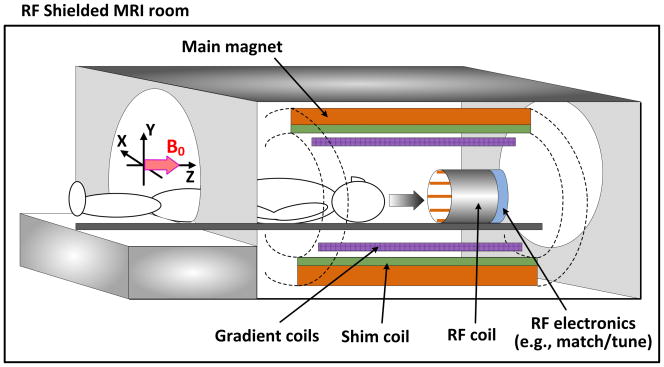
Magnetic resonance imaging (MRI) is used to obtain important information about the anthropotomy [1–6]. One trend of MRI systems is the move to higher static magnetic field (B0) generated by the main magnet in Fig. 1. The clinical 1.5 tesla (T) magnet is being replaced by 3T in hospitals for diagnostic and clinical purposes. In addition, 7T and 9.4T (called ultra-high field) systems are being used for animal and human images for research purposes because they have higher signal-to-noise ratio (SNR), better spatial resolution, and contrast in MR images [1,3,5]. SNR correlates with linear fashion with the field strength of the main magnet and is roughly twice as great at 3T as at 1.5T [7].
Fig. 1.
A structure illustration of a general Magnetic Resonance Imaging (MRI) scanner.
Although the above-mentioned benefits at ultra-high fields, the use of higher frequencies (approximately 300 MHz for 7T, 400 MHz for 9.4T, and 450 MHz for 10.5T) become problematic. At these higher frequencies, generating B1 RF fields is hampered by decreased penetration in the human body and RF interference appears resulting in spatially anomalous MR images because wavelengths become shorter than anatomic dimensions [8, 9]. The use of higher frequencies also complicates the design and implementation of RF coils [10, 11].
To create a uniform RF magnetic near-field, the microstrip line is modified to have a double trapezoidal conductor shape. An eight-channel double trapezoidal microstrip element RF coil has been built and has been operated in a 7T MRI scanner. Simulation and experimental results of this RF head coil are compared to the results from a similar eight-channel RF coil with a uniform microstrip element coil, and it is shown that the trapezoidal element coil has improved B1 near-field strength and uniformity of the near-field profile.
II. RF COIL ELEMENTS
An RF coil creates a time-varying RF magnetic near-field (B1) at the Larmor frequency in a specific region (e.g., the head, knee, breast, etc) of the human body. RF coil elements are tuned to resonate at the Larmor frequency and matched to the RF source impedance using capacitive and inductive components. The performance of RF coil significantly impacts the MR image quality. Therefore, various types of RF coils have been proposed including loops, the birdcage coil and the transverse electromagnetic (TEM) coil.
A. TEM RF coil element
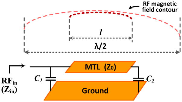
The RF coil design has moved from the standard birdcage coils to the pioneering TEM coil, which allows multichannel operation and RF shimming. The TEM coil has transmission line elements, usually microstrip transmission lines (MTL) with finite dimension ground planes [12, 13]. Fig. 2 shows a schematic diagram of a single RF coil element of the TEM microstrip line and the contour of the RF magnetic near-field along the length of the microstrip line. The resonant length of the microstrip element (l) is foreshortened from λ/2 by capacitors (C1 and C2) at the ends. The estimated input impedance of this TEM RF microstrip line coil element is given by
Fig. 2.
A schematic diagram of TEM RF coil element and a sketch of the axial RF near-field along the line length.
| (1) |
where β (=2π/λ) is the phase constant, l and Z0 are the length and the characteristic impedance of the microstrip line, respectively. ZC1 is 1/jωC1, and ZC2 is 1/jωC2 [13].
To meet the resonance condition (Zin→∞) in a lossless parallel circuit, the denominator should become zero. In the case both capacitances are identical (C = C1 = C2), the capacitance value is
| (2) |
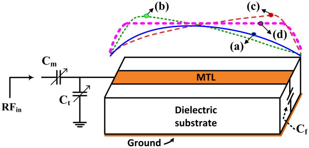
Fig. 3 shows that each element is terminated by capacitors. The tuning capacitor (Ct), matching capacitor (Cm), and fixed-value end capacitor (Cf). The Ct is adjusted to tune the resonance frequency to the Larmor frequency and the Cm is adjusted to match the resonator to the source impedance of 50 ohm. The Ct and Cf can be estimated from (2). Matching capacitor (Cm) is connected in series. The input impedance of the TEM RF coil element is matched to 50 ohm at the Larmor frequency by adjusting both Cm and Ct simultaneously.
Fig. 3.
Sketch of generated RF magnetic near-field (B1) distributions of a TEM coil element along the length of a MTL (in YZ plane): (a) a balanced condition, (b) (c) unbalanced conditions, and (d) a balanced and improved uniformity condition.
The distribution of RF magnetic near-fields (B1) should be symmetric and uniform in the subject. The transverse RF magnetic near-field, however, is still a maximum around the axial center if the capacitors are equal and falls off towards the ends of the element as shown in Fig. 3(a). Fig. 3(b) and (c) illustrate asymmetric magnetic near-fields due to unbalanced capacitive conditions between the front (Ct and Cm) and end side (Cf). Therefore, the combination of the tuning and matching capacitors (Ct and Cm) should be balanced with the end capacitor (Cf).
Fig. 3(d) is the desired RF magnetic near-field with a balanced and improved uniformity. This study aims to obtain this desired magnetic near-field profile.
B. Stepped impedance coil element
The field distribution along the microstrip line may be altered by shaping the conductor. One method uses stepped or alternating impedances with repeating thick and thin conductor sections, to reduce the inhomogeneous RF magnetic field [14, 15]. These, however, create bumps in the magnetic RF near- field (referred to Fig. 6(c)).
Fig. 6.

(a) a simulation setup of a single element with a phantom and simulation results of cross-section magnetic field (H-field) distributions along the conductor line (YZ plane) according to the conductor shapes (top); (b) the uniform microstrip transmission line coil element, (c) the stepped impedance coil element, (d) the proposed double trapezoidal shape coil element and (e) the narrow version of (d).
C. Double trapezoidal coil element
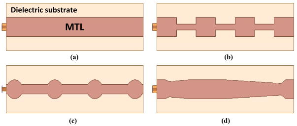
This paper presents a microstrip RF coil element with double trapezoidal conductor shape to create a uniform RF magnetic near-field as shown in Fig. 4(d) [19]. The following parts of this paper describe the electromagnetic simulations and MR experiments to show the superior performance of the double trapezoidal coil element.
Fig. 4.
Conductor shapes of MTL coil element: (a) uniform shape, (b) (c) stepped impedance shape, and (d) trapezoidal shape.
III. ELECTROMAGNETIC MODEL AND SIMULATION
The electromagnetic simulation data (Driven modal of the solution type in HFSS by Ansys) was used to evaluate and analyze the proposed trapezoidal shape by comparing the results with other structures shown in figure 4(a) to (c) for the 7T (fLarmor = 297.2 MHz) MRI system.
A. Single element models and simulations
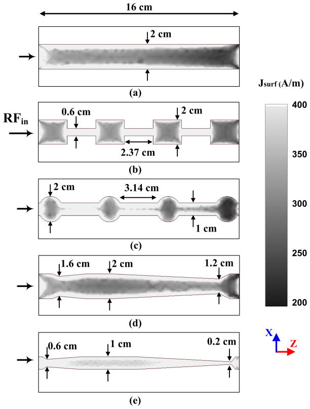
Fig. 5 shows the current densities on the conductor surface of the different element shapes given in Fig. 4(a) to (d). Fig. 5(a) is a uniform microstrip line and its current density gradually weaken away from the RF input side. Fig. 5(b) and (c) are the stepped impedance elements that have periodic current density variation. Fig. 5(d) and (e) are the proposed double trapezoidal shapes that have the most uniform current distributions. Fig. 5(e) shows that the narrow version of the trapezoidal shape has a uniform and higher current density. From these results, the trapezoidal RF coil elements may induce most uniform B1 near-field, and the narrow conductor shape may have higher B1 near-field. For electromagnetic models and simulations, Cf has a fixed value of 2.2 pF for Fig. 5(a)–(d) and 3.3pF for Fig. 5(e). Both Cm and Ct are re-adjusted at each coil element to be tuned and matched after a phantom model is loaded. Teflon (εr = 2.1, dielectric loss tangent = 0.0002, and dielectric thickness = 1.9 cm) is used for a dielectric substrate model.
Fig. 5.
Simulation results of surface current density (Jsurf) distributions: (a) the uniform MTL coil element, (b) (c) stepped impedance coil element, (d) the proposed double trapezoidal shape coil element and (e) the narrow version of (d).
Fig. 6(a) shows a simulation setup installed a phantom model (εr = 58.1 and σ = 0.539 S/m). The frame of the dielectric substrate has a diameter of 25.4 cm and length of 16 cm. Fig. 6(b) to (e) are the simulation results of the RF magnetic (H) near-field using the uniform coil element in Fig. 5(a), the stepped impedance coil element in Fig. 5(b), the proposed double trapezoidal coil element in Fig. 5(d), and Fig. 5(e), respectively. The results follow the patterns of the current density on the conductors as expected. Most uniform and symmetric RF magnetic near-fields are obtained with the double trapezoidal coil elements. Moreover, the narrow version creates higher intensity as well as a uniform profile.
B. Multi-channel volume coil and model
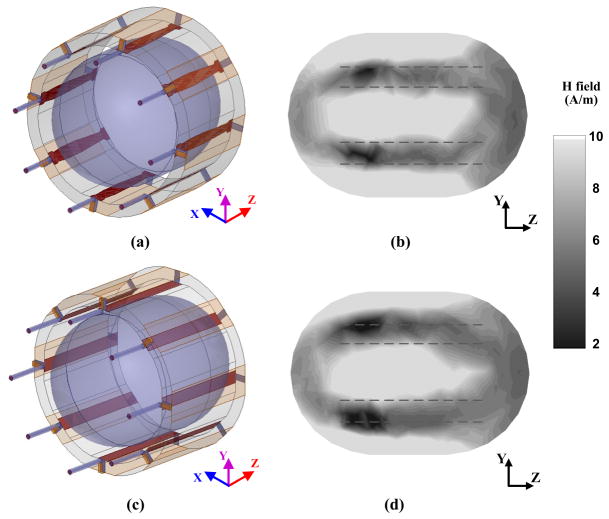
The eight-channel volume coil comprises of an array of the microstrip transmission line elements that are operated as independent coil elements. Eight channels are placed with individual elements symmetrically and the diameter of the TEM RF head coil is 25.4 cm. Capacitance (Cf) at the end from the feed points is fixed at 2.2 pF, and matching and tuning capacitances (Cm and Ct) are 4.65 pF and 8.2 pF, respectively. The phantom model is loaded and tuning/matching capacitors have been re-adjusted to tune and match the impedance to 50. Each element is resonated for the Larmor frequency (7T = 298 MHz) driven with 45° phase difference. The final capacitance ranges are from 4.45 pF to 4.65 pF for the matching capacitor (Cm) and from 7.2 pF to 8.85 pF for the tuning capacitor (Ct). Fig. 7(b) and (d) are plane across-section slices (YZ plane) at the center with an array of trapezoidal and uniform RF coil elements. The B1 near-field inside the phantom in Fig. 7(b) has improved the penetration depth and homogeneity with the double trapezoidal element.
Fig. 7.
Multi-channel volume coil simulation setup and results with a phantom model: (a) RF coil with the double trapezoidal shape, (b) the cross-section of the magnetic (H) field of (a) in YZ plane, (c) RF coil with the uniform shape, and (d) the cross-section of the magnetic (H) field of (c) in YZ plane.
IV. EXPERIMENTAL METHOD AND RESULTS
A. Experimental methods
Two eight-channel RF head coils have been built with the conductor shapes of Fig. 4(a), a uniform microstrip element, and (d), a double trapezoidal microstrip element, as shown in Fig. 8. Each element comprises of a low loss Teflon substrate (εr = 2.2) with height and length of 1.9 cm and 16 cm, respectively. To build the trapezoidal shapes, the maximum width of the copper taped conductor is 1.9 cm and is cut down to the minimum width of 0.9 cm at the far side and 1.3 cm at the RF input side. Each element is individually matched to the 50 Ω coaxial cable and tuned to 297.2 MHz for the operation of 7T MRI. To improve the isolation between adjacent elements, wide strips of copper tape are placed over the finite ground planes to create capacitances. For tuning and matching capacitors, NMA10 (1~ 10 pF, 1000 V) by Voltronics (Salisbury, MD) are used. A C-type capacitor (4.4 pF, 2500 V) by ATC (Huntington, NY) is used for the terminated end capacitor (Cf).
Fig. 8.
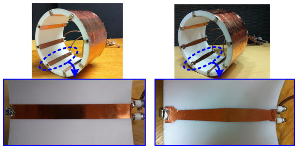
(a) the uniform and (b) the proposed double trapezoidal 8 channel RF head coils and individual elements (zoomed).
Experiments have been performed with a cylindrical 8 liter phantom filled with a sucrose/saline solution (εr = 58.1 and σ = 0.539 S/m) consisting of sucrose (47.6%), distilled water (51.1%), and salt (1.3%). The phantom is designed to represent the electrical properties of the human head and has roughly the same dimension as a human head. The phantom is positioned at the same location for each experiment. Each of the eight RF outputs is wired to custom-built Transmit/Receive switches allowing for both transmitting and receiving operations. The final reconstruction images from each receiving element are combined as the root of the sum of squares. The transmitted RF magnetic field (B1+) mapping and the received RF field (B1−) shimming calculations are performed in Matlab software. In the phantom experiments, incremental geometric phase sets are used for B1+ mapping and the neighboring elements drive phases are incremented by 45 degrees [20].
B. Experimental results
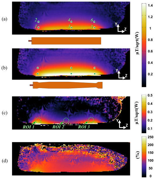
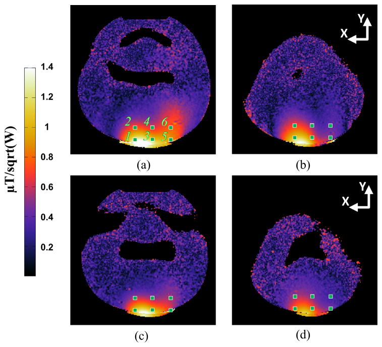
Fig. 9 shows the experimental setup in the Siemens Magnetom 7T MRI with the 90 cm bore actively shielded magnet in the center for magnetic resonance research (CMRR), University of Minnesota. Fig. 10 presents the experimental MR signal penetration depth and width of the B1+ map inside the cylindrical phantom along the microstrip line (sagittal plane, YZ plane) within the effective RF coil length. The results are consistent with the simulation results of Fig. 6(b) and (d). Compared to the result of the uniform conductor shape in Fig. 10(a), the double trapezoidal shape has more uniform field distribution with higher signal penetration depth in Fig. 10. (b). Table 1 shows the sampled B1+ values in Fig. 10(a) and (b). The calculated improvements have the range of 7% to 61% and average 29.3%. Fig. 10(c) shows the subtraction result from (b) to (a) and the improvement as a percentage is shown in Fig. 10(d). The proposed double trapezoidal coil element increases about 35% at the region of interest (ROI) 1 and 25% at the ROI 3 as well as about 13% at the ROI 2 in Fig. 10(c). Better results are expected if the narrow version in Fig. 5(e) is utilized. Fig. 11 shows a different plane (XY plane) view focusing on the effect at the center and end region along the microstrip line of the TEM RF coil element. The average improvement by the sampled points is 20.6% at the center region when comparing (a) with (b) and 36.4% at the end region when comparing (c) with (d).
Fig. 9.
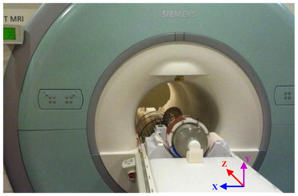
MRI experimental setup at 7T in CMRR (Center for Magnetic Resonance Research at University of Minnesota).
Fig. 10.
Experimental B1+ map results (μT/sqrt(W)) inside a phantom along the length of the RF coil element (YZ plane) and the sampled points (1 to 6) with; (a) the uniform single element, (b) the proposed double trapezoidal single element, (c) the subtraction from (b) to (a), and (d) the B1+ field improvement as a percentage.
TABLE I.
INDUCED B1+ INTENSITY COMPARISONS BETWEEN THE TRAPEZOIDAL AND UNIFORM ELEMENT IN FIG. 10
| Position | 1 | 2 | 3 | 4 | 5 | 6 |
|---|---|---|---|---|---|---|
| Shape | ||||||
| Trapezoid (Fig. 10. (b)) | 0.98 | 0.58 | 1.36 | 0.85 | 1.29 | 0.7 |
| Uniform (Fig. 10(a)) | 0.61 | 0.42 | 1.17 | 0.79 | 0.97 | 0.58 |
| Improvement (%) | 61 | 38 | 16 | 7 | 33 | 21 |
| Average Improvement (%) | 29.3 | |||||
Fig. 11.
Experimental B1+ map results (μT/sqrt(W)) inside a cylindrical phantom with a XY plane perpendicular to the length of the element and the sampled points (1 to 6). The central slices of (a) the trapezoidal and (b) uniform single coil element, and end region slices of (c) the trapezoidal and (d) uniform single coil element.
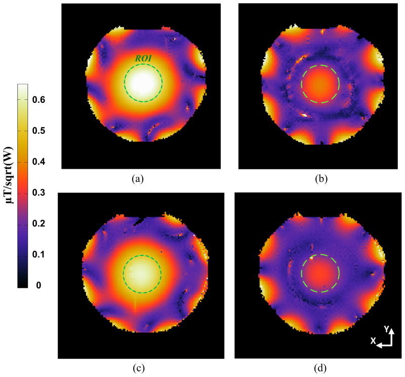
Fig. 12 shows B1+ map slices inside a phantom along XY plane to check and compare the performance of the 8-channel RF head coils using the double trapezoidal and the uniform conductor shapes. By comparing the data inside the ROI circle, the center and end region slice, Fig. 12(a) and (b), of the RF coil with the trapezoidal elements obtain stronger intensity of 4.9% and 10.8% than Fig. 12(c) and (d) of the RF coil with the uniform elements. Although a multi-channel RF coil has complicated coupling and interference with adjacent coil elements, this 8-channel’s result shows higher B1+ field are obtained with the proposed trapezoidal shape and confirms the theoretical expectation, EM simulation results, and the experimental results with a single element.
Fig. 12.
Experimental 8-channel RF coil B1+ map slices (μT/sqrt(W)) inside a cylindrical phantom along XY plane. The center slices of (a) an 8-channel RF coil with the proposed double trapezoidal elements and (c) the uniform shape elements, and end region slices of (b) with trapezoidal and (d) uniform elements.
V. CONCLUSION
A TEM RF head coil with double trapezoidal microstrip shape is introduced to generate uniform RF magnetic field (B1) along the length of the RF coil. By the results of simulations and experiments, the proposed RF head coil compensates the field deterioration at the ends and demonstrates improved RF magnetic near-field uniformity as well as higher intensity. This technique can be a strong candidate for local RF shimming and provide high quality MR images.
Acknowledgments
This study was supported by the Keck Foundation and the following U.S National Institute of Health (NIH) grants: NIH-R01 EB000895, R01 EB006835, R01 EB007327, BTRR NIH-P41 RR08079, P30 NS057091, R21 EB009133.
This work is supported by NIH-NIBIB 2R01 EB006835, NIH-NIBIB 2R01 EB007327, S10 RR026783, and NIH-NIBIB -P41-EB015894
Biographies

Sung-Min Sohn (S’11-M’13) received the B.S. and M.S. degrees from Korea University, Seoul, Korea, in 2002 and 2004, and the Ph.D degree from University of Minnesota, Minneapolis, MN, USA in 2013.
From 2004 to 2007, he was a circuit design engineer in Analog/Mixed circuit group at LG Electronics, Seoul, Korea, where he performed research on camera image processor and high speed serial link. He is currently a postdoctoral researcher in CMRR (center for magnetic resonance research) at university of Minnesota. His research is focusing on RF/analog circuits for MRI electronics and novel RF coil design.

Lance DelaBarre (M’13) received his B.S in Physics from North Dakota State University in 1995 and his Ph. D. in Biophysical Sciences and Medical Physics from the University of Minnesota in 2001. His research has focused on the challenges and rewards of high-field magnetic resonance (4 T, 7 T and 9.4 T) at the Center for Magnetic Resonance Research at the University of Minnesota. His areas of research have included RF pulse and sequence design, Magnetic Resonance Spectroscopy, High Resolution NMR, parallel transceivers and MRI RF coil design and testing.
Anand Gopinath (S’64–M’65–SM’80–F’90–LF’02) received the Ph.D. and D.Eng. (higher doctorate) degrees by the University of Sheffield, U.K.
He was Reader in Electronics at the University College of North Wales (1978), and also held the Chair of Electronics in Chelsea College, now merged with King’s College (1981–1982), University of London, London. He was Research Staff Member at MIT Lincoln Laboratory (1978–1981, 1982–1986), and then joined the University of Minnesota as Professor of Electrical and Computer Engineering. He was Director of the Microelectronics Laboratory (now the Nano Fabrication Center), University of Minnesota, in 1989–1994. He has performed research in the field of RF/microwaves, and published extensively in the areas of guided wave structures, devices and circuits, and has recently directed a project in the area of scattering. He has also worked in the Integrated Optics and Optoelectronics areas, and he has published on a variety of devices and modeling in the area. His most recent projects are on very fast Analog to Digital Converters in CMOS, electromagnetic wave scattering from high dielectric constant cubes and MRI RF coils.
He is Fellow of Optical Society of America and also Fellow of IET, London.

J. Thomas Vaughan (SM’06) received the two B.S. degrees in electrical engineering and biology at Auburn University, Birmingham, AL, and the Doctoral degree in biomedical engineering from the University of Alabama at Birmingham, Birmingham, in 1993.
After receiving the degree, he joined Kennedy Space Center at NASA. Following the first Space Shuttle launch, he was recruited for a DOD project at Texas Instruments in Dallas before continuing his graduate education and employment at the University of Texas Southwestern. Here, he was the RF Engineer on a project to construct the first 2 T human NMR system begun in 1984.
In 1989, he took the post of the Chief Engineer for a University of Alabama Philips Research Labs consortium to build the first 4T system sited in the U.S. After receiving the Doctoral degree, he became an Assistant Professor at Harvard University and Assistant in Physics and Director of Engineering at the Massachusetts General Hospital NMR Center. Following a four year term at the MGH to help commission a 3 T system and launch a 7 T program, he accepted tenure at the University of Minnesota in 1999 where he continues his work at 4 T, 7 T, 9.4 T, and beyond. He is currently a Professor in the Departments of Radiology, Electrical Engineering and Biomedical Engineering, University of Minnesota, Minneapolis.
Dr. Vaughan administers the Engineering Core of the Center for Magnetic Resonance Research.
Contributor Information
Sung-Min Sohn, Email: sohnx021@umn.edu, Department of Electrical and Computer Engineering, University of Minnesota. He is now with Center for Magnetic Resonance Research (CMRR), University of Minnesota, Minneapolis, MN 55455 USA.
Lance DelaBarre, Email: dela0087@umn.edu, Center for Magnetic Resonance Research (CMRR), University of Minnesota, Minneapolis, MN 55454.
Anand Gopinath, Email: gopinath@umn.edu, Department of Electrical and Computer Engineering, University of Minnesota, Minneapolis, MN 55455 USA.
John Thomas Vaughan, Email: vaugh020@umn.edu, Department of Electrical and Computer Engineering and with the Center for Magnetic Resonance Research (CMRR), University of Minnesota, Minneapolis, MN 55455 USA.
References
- 1.Vaughan T, DelaBarre L, Snyder C, Tian J, Akgun C, Shrivastava D, Liu W, Olson C, Adriany G, Strupp J, Andersen P, Gopinath A, van de Moortele PF, Garwood M, Ugurbil K. 9.4T human MRI: Preliminary results. Magnetic Resonance in Medicine. 2006;56:1274–1282. doi: 10.1002/mrm.21073. [DOI] [PMC free article] [PubMed] [Google Scholar]
- 2.Ugurbil K, Garwood M, Ellermann J, Hendrich K, Hinke R, Hu X, Kim SG, Menon R, Merkle H, Ogawa S. Imaging at high magnetic fields: initial experiences at 4T. Magn Reson Q. 1993;9(4):259–277. [PubMed] [Google Scholar]
- 3.Vaughan JT, Garwood M, Collins CM, Liu W, DelaBarre L, Adriany G, Adersen P, Merkle H, Gebel R, Smith MB, Ugurbil K. 7T vs. 4T: RF power, homogeneity and signal-to-noise comparison in head images. Magnetic Resonance in Medicine. 2001 Jul;46:24–30. doi: 10.1002/mrm.1156. [DOI] [PubMed] [Google Scholar]
- 4.Duyn JH. The future of ultra-high field MRI and fMRI for study of the human brain. Neuroimage. 2012;62(2):1241–1248. doi: 10.1016/j.neuroimage.2011.10.065. [DOI] [PMC free article] [PubMed] [Google Scholar]
- 5.Ibrahim Tamer S, Chad Mitchell, Petra Schmalbrock, lee Robert, Chakeres Donald W. Electromagnetic perspective on the operation of RF coils at 1.5–11.7 Tesla. Magnetic Resonance in Medicine. 2005;54:683–690. doi: 10.1002/mrm.20596. [DOI] [PubMed] [Google Scholar]
- 6.Berliner P-MRaL. Ultra high field magnetic resonance imaging. Springer; 2006. [Google Scholar]
- 7.Marzola Pasquina, Osculati Francesco, Sbarbati Andrea. High field MRI in preclinical research. Eur J Radiol. 2003;48(2):165–170. doi: 10.1016/j.ejrad.2003.08.007. [DOI] [PubMed] [Google Scholar]
- 8.Schick F. Whole-body MRI at high field: technical limits and clinical potential. European radiology. 2005;15(5):946–959. doi: 10.1007/s00330-005-2678-0. [DOI] [PubMed] [Google Scholar]
- 9.Collins CM, Liu W, Schreiber W, Yang QX, Smith MB. Central brightening due to constructive interference with, without, and despite dielectric resonance. J Magnetic Resonance Imaging. 2005;21(2):192–196. doi: 10.1002/jmri.20245. [DOI] [PubMed] [Google Scholar]
- 10.Sung-Min S, DelaBarre L, Vaughan JT, Gopinath A. 8-Channel RF head coil of MRI with automatic tuning and matching. IEEE MTT-S International Microwave Symposium Digest; Jun. 2013. [Google Scholar]
- 11.Sung-Min S, Vaughan JT, Gopinath A. Auto-tuning of the RF transmission line coil for high-fields magnetic resonance imaging (MRI) systems. IEEE MTT-S International Microwave Symposium Digest; Jun. 2011. [Google Scholar]
- 12.Vaughan JT, Adriany G, Snyder CJ, Tian J, Thiel T, Bolinger L, Liu H, DelaBarre L, Ugurbil K. Efficient High-Frequency Body Coil for High-Field MRI. Magnetic Resonance in Medicine. 2004 Oct;52(4):851–859. doi: 10.1002/mrm.20177. [DOI] [PubMed] [Google Scholar]
- 13.Vaughan JT, Griffiths John R. RF Coils for MRI. Wiley; 2012. [Google Scholar]
- 14.Akgun CE, DelaBarre L, Snyder CJ, Sohn S-M, Adriany G, Ugurbil K, Gopinath A, Vaughan JT. Alternati ng Impedance Mult-Channel Transmission Line Resonators for High Field Magnetic Resonance Imaging. IEEE MTT-S International Microwave Symposium Digest; May 2010.pp. 756–759. [Google Scholar]
- 15.Elabyad IA, Omar A. An Investigation of Alternating Impedance Microstrip Transceiver Coil Arrays for MRI at 7T. IEEE MTT-S International Microwave Symposium Digest; Jun. 2011; pp. 1–4. [Google Scholar]
- 16.Yang QX, Wang JH, Zhang XL, Collins CM, Smith Michael B, Liu H, Zhu XH, Vaughan JT, Ugurbil K, Chen Wei. Analysis of wave Behavior in Lossy dielectric samples at high field. Magnetic Resonance in Medicine. 2002 May;47(5):982–989. doi: 10.1002/mrm.10137. [DOI] [PubMed] [Google Scholar]
- 17.Ibrahim Tamer S, Lee Robert, Baertlein BA, Abduljalil Amir M, Zhu Hui, Robitaille P-ML. Effect of RF coil excitation on field inhomogeneity at ultra high fields: a field optimized TEM resonator. Magnetic Resonance Imaging. 2001;19:1339–1347. doi: 10.1016/s0730-725x(01)00404-0. [DOI] [PubMed] [Google Scholar]
- 18.Silvester P. TEM wave properties of microstrip transmission lines. Electrical Engineers, Proceedings of the Institution of. 1968;115(1):43–48. [Google Scholar]
- 19.Sung-Min S, DelaBarre L, Vaughan JT, Gopinath A. RF multi-channel head coil design with improved B1+ Fields uniformity for high field MRI systems. IEEE MTT-S International Microwave Symposium Digest; Jun. 2012; pp. 1–3. [Google Scholar]
- 20.Insko EK, Bolinger L. Mapping of the Radiofrequency Field. Journal of Magnetic Resonance, Series A. 1993;103:82–85. [Google Scholar]


