Abstract
An all-optical ultrasound probe for vascular tissue imaging was developed. Ultrasound was generated by pulsed laser illumination of a functionalized carbon nanotube composite coating on the end face of an optical fiber. Ultrasound was detected with a Fabry-Pérot (FP) cavity on the end face of an adjacent optical fiber. The probe diameter was < 0.84 mm and had an ultrasound bandwidth of ~20 MHz. The probe was translated across the tissue sample to create a virtual linear array of ultrasound transmit/receive elements. At a depth of 3.5 mm, the axial resolution was 64 µm and the lateral resolution was 88 µm, as measured with a carbon fiber target. Vascular tissues from swine were imaged ex vivo and good correspondence to histology was observed.
OCIS codes: (110.5125) Photoacoustics, (110.2350) Fiber optics imaging, (060.2380) Fiber optics sources and detectors, (170.7170) Ultrasound, (170.0110) Imaging systems
1. Introduction
High frequency, miniature ultrasound probes such as intravascular ultrasound (IVUS) and intracardiac echocardiography (ICE) catheters can be invaluable for guiding minimally invasive medical procedures such as coronary stent placement and cardiac ablation [1,2]. In current-generation ultrasound probes, ultrasound is typically generated and received electrically using piezoelectric [3] or capacitive micromachined transducers [4]. The complexities involved with fabricating these electrical probes can result in high costs that limit their clinical applicability. For instance, mechanically dicing and electrically connectorizing piezoelectric elements can become challenging as their dimensions become smaller and the ultrasound frequencies become higher. Additionally, it can be challenging to achieve wide transmission bandwidths and adequate wideband reception sensitivity with small piezoelectric elements. Optical methods for transmitting and receiving ultrasound are emerging as alternatives to their electrical counterparts [5–8]. They offer several distinguishing advantages including the potential to generate and detect the broadband ultrasound fields (tens of MHz) required for high resolution endoscopic imaging. Moreover, optical methods that employ optical fibers for ultrasound transmission and reception can provide the required level of miniaturisation for minimally invasive use and be of sufficiently low cost to be used as disposable devices.
Broadband ultrasound can be generated optically via the photoacoustic effect, in which modulated incident light is absorbed by a material and the resulting deposition of thermal energy leads to a temperature increase and a resulting propagating ultrasound wave [9]. To achieve high optical-ultrasound transduction efficiency, a material with a high optical absorption coefficient and a high thermal expansion coefficient is desirable [9]. Recent studies have highlighted the efficacy of composite materials that comprise optical absorbers integrated within elastomers [5,10,11]. The authors recently demonstrated a method for creating ultrasound transmitters at the tip of an optical fiber using a composite material comprised of functionalised multi-walled carbon nanotubes (CNTs) and polydimethylsiloxane (PDMS) [12]. Using optical fibers with 200 µm core diameters, ultrasound pressures of 4.5 MPa were achieved, with corresponding bandwidths of 15 MHz. These acoustic parameters are comparable with those of conventional piezoelectric transmitters used for high resolution ultrasound imaging.
Several methods for detecting ultrasound at the tip of an optical fiber have been explored with those based on interferometry [13–16] or Bragg grating sensors [17] offering the highest broadband sensitivity. One promising approach exploits the detection of acoustically-induced changes in the reflectance of a polymer Fabry-Pérot (FP) cavity [18,19]. This type of sensor can provide high sensitivity, a broad bandwidth extending to several tens of MHz and acoustically small element sizes. In addition, the sensor can be formed at the tip of a single mode optical fiber allowing realisation of highly miniaturised (125µm o.d) receivers [20,21].
Whilst all-optical ultrasound images have been demonstrated previously [5–8], there is a need to miniaturise the optical designs in order to make them compatible with interventional devices. In this paper, we describe a novel miniature fiber optic probe that is based on the two concepts outlined above: a fiber optic transmitter that employs a CNT based absorbing film [12] for generating broadband ultrasound and a fiber-optic FP polymer sensor [21] for receiving it. This combination provides a miniaturised, all-optical ultrasound probe with a bandwidth and a detection sensitivity that permits high resolution pulse-echo ultrasound imaging of soft tissue.
2. Experimental methods
2.1 Setup
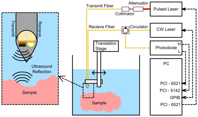
The fiber optic ultrasound transmitter comprised a custom CNT-PDMS composite material at the distal end face of a 200 µm core silica fiber (FG200LEA, Thorlabs, UK). The methods for creating this material and applying it to the optical fiber end face were previously described [12]. Briefly, the composite was created by mixing functionalised CNTs, xylene and PDMS. As a volatile solvent, the xylene decreased the viscosity of the PDMS, and the functionalization allowed for uniform dispersion of CNTs in xylene. The normally cleaved fiber end face was dip coated with the composite using a motorised stage and left to cure in ambient conditions. The resulting fiber optic transmitter generated a peak ultrasound pressure at the end face that was greater than 4 MPa, with a bandwidth of 15 MHz and a centre frequency of 18 MHz. The excitation light was provided by a compact diode pumped Q-switched Nd:YAG laser (SPOT-10-500-1064, Elforlight, UK) with a wavelength 1064 nm, a pulse width 2 ns, and a repetition rate of 100 Hz. Prior to fiber-coupling, the laser pulse energy was attenuated to 30.2 µJ per pulse, so that the fluence at the fiber end face was 96.1 mJ/cm2.
The fiber optic ultrasound receiver comprised a polymer (FP) sensing cavity located at the distal end of a single mode optical fiber. The cavity is of a similar design to that reported previously [21]. Briefly, it comprised an epoxy spacer of thickness 20.1 µm sandwiched between two dielectric mirror coatings with ~98% reflectivity. One coating was deposited directly onto the fiber end face cleaved at normal incidence; the other, on the distal surface of the polymer spacer. A Parylene-C coating with a thickness of 10 µm was applied to protect the distal dielectric mirror coating. The sensor was interrogated using a continuous wave, tuneable laser (Tunics T100S-HP CL, Yenista Optics, France) operating in the wavelength range 1500-1600 nm. In order to bias the FP cavity so as to provide optimum sensitivity, the interrogation wavelength was adjusted so that it corresponds to the peak derivative of the cavity transfer function [19]; under these conditions a small acoustically-induced modulation of the polymer spacer thickness is linearly converted to a corresponding modulation of the optical power reflected from the cavity. An optical circulator was used to deliver the interrogation light to the FP cavity and return the reflected light to a custom 50 MHz photodiode-transimpedance amplifier unit with low-frequency (< 50 kHz) and high-frequency (> 500 kHz) outputs. The low-frequency output was digitized at 16 bits with a sample rate of 1 MS/s (PCI-6251, National Instruments, UK) and used to record the FP cavity transfer function. The high-frequency output was digitized at 14 bits with a sample rate of 100 MS/s (PCI-5142, National Instruments, UK) and used to record the time-varying reflected optical power modulation produced by the incident ultrasound wave. The ultrasound bandwidth of the sensor was approximately 20 MHz.
Within the probe, the ultrasound transmitter and receiver were held together using heat shrink tubing. The probe was positioned within a stainless steel tube (internal diameter: 0.84 mm). The distal end faces of the optical fibers were both recessed 1 mm from the end of the tube. The probe was mounted on a motorized translation stage (MTS50/M-Z8, Thorlabs, UK) and submerged in a water bath. To acquire ultrasound images, the probe was translated laterally with respect to the sample surface (Fig. 1 ).
Fig. 1.
Imaging system setup with an expanded section (left) showing the ultrasound generation and detection fiber within tubular metal housing (inner diameter 0.84 mm).
2.2 Cross-talk removal
Ultrasound that propagated directly from the fiber optic ultrasound transmitter to the receiver and subsequent reflections within the metal tube resulted in cross-talk image artifacts (Fig. 2(a) ). Signal processing was performed to remove them prior to image reconstruction.
Fig. 2.
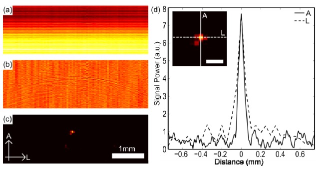
Results from a 7 µm carbon fiber at 4.5 mm depth. (a) Raw image. (b) Image after cross-talk removed. (c) Image after cross-talk removed and reconstruction, with axial (A) and lateral (L) dimensions labelled. (d) Axial and lateral cross-sections taken through the reconstructed image shown in (c) with profile inset (scale bar = 200 µm).
Prior to cross-talk removal, a digital high-pass filter (4th order Butterworth; cut-off: 5 MHz) was applied to reduce noise. For cross-talk removal, the digitized received ultrasound signal at the ith lateral position of the probe was modelled as follows:
| (1) |
where is the measured signal, is the cross-talk signal, is the reflected ultrasound signal, and is the random background noise. Each term is a discrete time series corresponding to the digitised signal values. To estimate the cross-talk term, a moving average across signals from multiple lateral positions was performed. Under the assumption that the reflected signal changes significantly across lateral positions, the average reflected signal was assumed to be negligible with respect to the average cross-talk signal. With the additional assumption that the noise term is negligible, the following approximation was obtained:
| (2) |
where the brackets indicate a moving average. The cross-talk signal at the ith lateral position of the probe was assumed to be related to the moving average as follows:
| (3) |
where was estimated using Eq. (2), with the average performed across a window of 20 measured signals centred at the ith lateral position. The first coefficient, , allowed for cross-talk signals to differ from each other by an offset. The second term, , allowed for variation in the amplitudes of the cross-talk signals. The third term, , allowed for small temporal offsets between cross-talk signals. The use of temporal derivatives to model temporal offsets has been used previously in the context of functional Magnetic Resonance Imaging [22].
In Eq. (3), the coefficients and are unknown. To estimate them, Eq. (3) was substituted into Eq. (1) and written in matrix notation, in the form of a general linear model [23]:
| (4) |
In Eq. (4), is the design matrix, and is a vector of coefficients. The first column of the design matrix is unity, the second is the moving average, and the third is the derivative of the moving average. For a general linear model, the coefficients are estimated with the following equation:
| (5) |
Neglecting the noise term, the estimated reflected signal, , was obtained by rearranging Eq. (4):
| (6) |
2.3 Image reconstruction
After application of the cross-talk removal algorithm, to reconstruct the images from the detected ultrasound, a k-space algorithm was used [24–26]. This reconstruction was performed with the assumption of evenly spaced, omnidirectional ultrasound receive elements and omnidirectional transmit beams which insonified the entire field of view. The reconstruction involved transforming the detected signals to the Fourier domain in both the lateral and temporal dimensions. To mitigate artifacts caused by the periodicity of the Fourier transform, zero padding was performed. The Fourier-transformed data was mapped to wavenumber-wavenumber space using the dispersion relation for a plane wave and subsequently inverse Fourier transformed to image space. A Hilbert transform was then applied to obtain the signal envelope, and the image was displayed on a logarithmic scale.
2.4 Spatial resolution measurements
To measure the spatial resolution of the reconstructed images, a carbon fiber with a diameter of 7 µm was used as a target from which to obtain point spread functions. The carbon fiber was mounted horizontally, parallel to the water surface and perpendicular to the probe translation axis. The image acquisition protocol included 200 lateral steps with a 50 µm lateral step size and a 100 ms settle time between stepping and acquisition; at each lateral position, an average of 10 A-lines was performed to improve the signal-to-noise ratio. The carbon fiber was positioned at 11 depths relative to the ultrasound probe, which ranged from 1.5 to 10.5 mm. The resolution was defined as the full-width-at-half-maximum (FWHM) of the resulting reconstructed point spread functions, evaluated in the axial and lateral dimensions.
2.5 Tissue imaging
To provide an initial indication of the capabilities of the probe, a swine aorta sample and a carotid artery sample were imaged ex vivo. Both samples were obtained immediately post-mortem from a swine at the Northwick Park Institute for Medical Research that had been used in the context of an experiment from a different research group. The samples were placed in phosphate buffered saline (PBS), refrigerated, and imaged within a period of 12 to 18 hours. Just prior to imaging, the vessels were cut parallel to their longitudinal axes and affixed on to a cork ring positioned above a polyurethane ultrasound attenuator (AptFlex F28, Precision Acoustics, UK) to allow for imaging of their inner surfaces. The ultrasound attenuator was used to prevent acoustic reflections from the sample holder and water bath. The image acquisition protocol included 400 lateral steps with a 50 µm lateral step size and a settle time of 100 ms. A-line averaging was not performed for either sample, so that there was only one A-line for each lateral position. After imaging, the samples were stored in formalin; histological analysis was performed with hematoxylin and eosin (H&E) staining.
3. Results
3.1 Spatial resolution measurements
With the spatial resolution measurements, cross-talk was the dominant contribution to the received ultrasound signals (Fig. 2(a)). After application of the cross-talk removal algorithm, reflections from the carbon fiber were apparent as a parabola (Fig. 2(b)). After image reconstruction, the carbon fiber was clearly visible (Fig. 2(c)). Axial and lateral cross-sections of the carbon fiber images all had prominent maxima from which the spatial resolution could be estimated (Fig. 2(d)).
The system resolution varied with the target depth (Fig. 3 ). The lateral resolution was optimal at a target depth of 3.5 mm, where it was 88 µm. At smaller depths, it worsened to 137 µm at 1.5 mm; at larger depths, it worsened to 230 µm at 10.5 mm. The axial resolution exceeded the lateral resolution at all depths; it was optimal at a depth of 2.5 mm, where it was 58 µm, and it was in the range of 58 to 79 µm over all depths. At depths greater than 10.5 mm, the reflections from the target were too weak to allow for accurate resolution measurements.
Fig. 3.
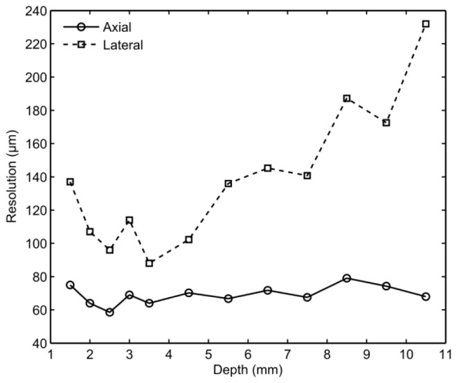
Measured ultrasound imaging system resolution in the axial dimension (circles) and in the lateral dimension (squares) for different target depths.
3.2 Tissue imaging
With the swine aorta sample, optical ultrasound imaging provided visualisation at all tissue depths (~2 to 7 mm), and the ultrasound attenuator beneath the tissue at a depth of 10 and 9 mm was apparent. Good correspondence between the optical ultrasound and the histological images was observed. In the latter images, the tissue appeared thinner and processing artifacts resulted in fragmentation of some regions beneath the tunica media layer. The tunica media layer presented as a largely homogenous speckled pattern (Fig. 4 ), although two reflective layers were visible at the surface which may have originated from the intima. With one cross-section, a side-branch was apparent, which presented as a region with decreased signal intensity and a depression at the tissue surface (Fig. 4(a), 4(c)). Additionally, a lymph node presented as a region with highly reflective structures. With a second cross-section, a clot-filled subsurface vessel was apparent as a region with low reflectivity (Fig. 4(b), 4(d)). In both images, residual cross-talk artifacts were present for depths shallower than 1 mm. Photoacoustic contributions to the images, which could have arisen from excitation light that was transmitted by the optically absorbing film and absorbed by tissue, were not detected.
Fig. 4.
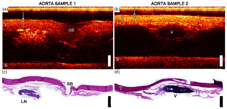
(a) and (b) Optical ultrasound image of swine aorta samples (scale bar 2 mm) with tunica media, T, cross-talk, X, the base of the tissue mount, B, a side branch, SB, a lymph node, LN, and a vessel, V, labelled. Arrows indicate two reflective layers, which may correspond to the intima. (c) and (d) show histology of aorta sections corresponding to images (a) and (b), respectively.
With the swine carotid artery sample, three distinct layers were visible (Fig. 5(a) ). Upon comparison with the histological images (Fig. 5(b)), the layers were identified as the tunica media (most superficial), the internal elastic lamina, and the adventia (deepest). The internal elastic lamina presented as a region with lower reflectivity than those of the adjacent layers. As with the aorta ultrasound images, cross-talk artifacts were apparent for depths less than 1 mm.
Fig. 5.
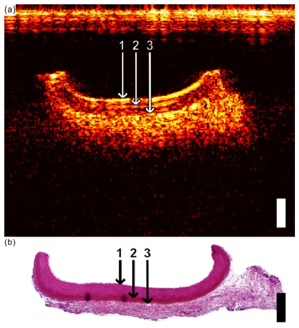
(a) Optical ultrasound image of the carotid artery, showing the tunica media (1 = top boundary; 2 = bottom boundary), the external elastic lamina (2 = top boundary; 3 = bottom boundary), and the adventitia (3 = top boundary). (b) Corresponding histological cross-section (H&E) of the carotid artery from which the layers in (a) were interpreted. In both (a), and (b), the scale bar corresponds to 1 mm for both axial and lateral dimensions.
4. Discussion
The all-optical ultrasound probe developed in this study provided images of vascular tissues that corresponded well to histology. Whilst all-optical ultrasound images have previously been obtained [5–8], those in this study were significant in terms of the detail with which tissue microstructure was visualised, and the compactness of the probe with which they were acquired. The high performance of the probe in this study stemmed from a combination of the high ultrasound pressures transmitted by the optically absorbing film and the high sensitivity of the concave FP ultrasound sensor. With its ability to visualise tissue layers, side branches and sub-surface structures such as lymph nodes, the probe provided information that could be useful for guiding intravascular minimally invasive procedures [1]. To the authors’ knowledge, it is the first study in which all-optical ultrasound imaging was performed with a fiber optic probe and reconstruction was performed with a virtual array of ultrasound transmitters/receivers.
The cross-talk algorithm was largely effective in mitigating cross-talk, but further improvements, such as the use of an ultrasound attenuating material between the transmit and receive fibers, could be considered in future versions of the probe. One advantage of the general linear model in this algorithm is that it implicitly incorporated variations in the excitation pulse energies. Additionally, the derivative term allowed for temporal shifts of the cross-talk that may have arisen due to variations in the distance between the transmit and receive optical fibers.
As with conventional ultrasound imaging, the axial resolution was limited by the bandwidths of the generated ultrasound and the ultrasound receiver. Optical ultrasound generation has the potential to provide high bandwidths with the use of short laser pulses used in this study [27]. For instance, Menichelli et al. showed that a nearly flat bandwidth from 20 to 50 MHz could be achieved with a 6 ns pulse. Given the brevity of the excitation light pulses, the bandwidth of the transmitted ultrasound was likely limited by attenuation within the composite coating. Indeed, high ultrasound attenuation in carbon nanotube-PDMS coatings were noted previously [10], and attenuation as high as 23 dB at 100 MHz was observed with a 25 µm composite comprising carbon black and PDMS [28]. The bandwidth of transmitted ultrasound may also have been limited by the coherent addition of ultrasound waves at different depths within the optically absorbing film. With optical absorption confined to sub-micron thicknesses, metallic structures such as Cr films can provide high ultrasound transmission bandwidths, but it appears that the maximum ultrasound pressures that they can provide are lower than those of CNT-PDMS composites [10]. The bandwidth of the received ultrasound depends on the FP cavity thickness which can be reduced to extend the bandwidth, albeit with a trade-off of a decrease in sensitivity. As all-optical ultrasound probes are refined in future studies, detailed performance comparisons with high resolution electrical ultrasound probes will be warranted.
The lateral resolution was limited by the angular aperture for reflected ultrasound provided by the virtual array, and the accuracy with which the spatial positions of the virtual array elements were known. In this bench-top imaging study, the accuracy with which the probe was positioned using the stepper motor (< 2 µm) was high relative to the wavelengths of transmitted ultrasound. In an in vivo context, in which the probe is integrated into a medical device such as a needle or a catheter, obtaining accurate measurements of its spatial position/orientation at different times as it is moved in the body in order to obtain a virtual array of ultrasound transmitters/receivers is likely to be challenging. This challenge could potentially be met with the use of fiber Bragg gratings or electromagnetic sensors [29,30]. Alternatively, a flexible fiber bundle could be used to scan excitation light to a series of specific spatial locations across an optically absorbing film.
Modifications to the probe design could allow for imaging within vessels or ducts, and for imaging with different modalities. For instance, the probe could be extended to a side-viewing probe, either by deflecting light for transmitting and receiving ultrasound, or by deflecting the ultrasound waves. The probe could also allow for light delivery to tissue for photoacoustic imaging or reflectance spectroscopy, either with a different type of optically absorbing film that is transmissive at certain wavelengths, or with an additional, un-coated optical fiber.
This study demonstrated that high resolution images of soft tissues that provide visualisation of clinically relevant structures can be obtained without signal averaging. As such, optical ultrasound imaging could be a viable method for guiding vascular and intracardiac interventions.
Acknowledgments
This work was supported in part by the EPSRC under Grant No. EP/J010952/1, by European Research Council under ERC-2012-StG Proposal 310970, European Union project FAMOS ( FP7 ICT, Contract 317744), and by the University College London-Cambridge University Photonic Systems Development Centre for Doctoral Training. The authors thank Dr. Malcolm Finlay at Barts Health NHS Trust and Dr. Bradley Treeby at University College London for their helpful comments, and Rashid Mohammed and Geoffrey Boxer at UCL Cancer Institute for histology.
References and links
- 1.Nissen S. E., Yock P., “Intravascular ultrasound: novel pathophysiological insights and current clinical applications,” Circulation 103(4), 604–616 (2001). 10.1161/01.CIR.103.4.604 [DOI] [PubMed] [Google Scholar]
- 2.Kim S. S., Hijazi Z. M., Lang R. M., Knight B. P., “The use of intracardiac echocardiography and other intracardiac imaging tools to guide noncoronary cardiac interventions,” J. Am. Coll. Cardiol. 53(23), 2117–2128 (2009). 10.1016/j.jacc.2009.01.071 [DOI] [PubMed] [Google Scholar]
- 3.Li X., Wu W., Chung Y., Shih W. Y., Shih W.-H., Zhou Q., Shung K. K., “80-MHz intravascular ultrasound transducer using PMN-PT free-standing film,” IEEE Trans. Ultrason. Ferroelectr. Freq. Control 58(11), 2281–2288 (2011). 10.1109/TUFFC.2011.2085 [DOI] [PMC free article] [PubMed] [Google Scholar]
- 4.Degertekin F. L., Guldiken R. O., Karaman M., “Annular-ring CMUT arrays for forward-looking IVUS: transducer characterization and imaging,” IEEE Trans. Ultrason. Ferroelectr. Freq. Control 53(2), 474–482 (2006). 10.1109/TUFFC.2006.1593387 [DOI] [PubMed] [Google Scholar]
- 5.Hou Y., Kim J.-S., Ashkenazi S., Huang S.-W., Guo L. J., O’Donnell M., “Broadband all-optical ultrasound transducers,” Appl. Phys. Lett. 91(7), 073507 (2007). 10.1063/1.2771058 [DOI] [Google Scholar]
- 6.Mosse C. A., Colchester R. J., Bhachu D. S., Zhang E. Z., Papakonstantinou I., Desjardins A. E., “Fiber-optic ultrasound transducers with carbon/PDMS composite coatings,” in Proceedings of SPIE Oraevsky A. A., Wang L. V., eds. (2014), Vol. 8943, p. 89430P. 10.1117/12.2037283 [DOI] [Google Scholar]
- 7.Hsieh B.-Y., Chen S.-L., Ling T., Guo L. J., Li P.-C., “All-optical transducer for ultrasound and photoacoustic imaging by dichroic filtering,” in 2012 IEEE International Ultrasonics Symposium (IEEE, 2012), pp. 1410–1413 10.1109/ULTSYM.2012.0352 [DOI] [Google Scholar]
- 8.Nuster R., Schmitner N., Wurzinger G., Gratt S., Salvenmoser W., Meyer D., Paltauf G., “Hybrid photoacoustic and ultrasound section imaging with optical ultrasound detection,” J. Biophotonics 6(6-7), 549–559 (2013). 10.1002/jbio.201200223 [DOI] [PubMed] [Google Scholar]
- 9.Cox B. T., Beard P. C., “Fast calculation of pulsed photoacoustic fields in fluids using k-space methods,” J. Acoust. Soc. Am. 117(6), 3616–3627 (2005). 10.1121/1.1920227 [DOI] [PubMed] [Google Scholar]
- 10.Won Baac H., Ok J. G., Park H. J., Ling T., Chen S.-L., Hart A. J., Guo L. J., “Carbon nanotube composite optoacoustic transmitters for strong and high frequency ultrasound generation,” Appl. Phys. Lett. 97(23), 234104 (2010). 10.1063/1.3522833 [DOI] [PMC free article] [PubMed] [Google Scholar]
- 11.Zou X., Wu N., Tian Y., Wang X., “Broadband miniature fiber optic ultrasound generator,” Opt. Express 22(15), 18119–18127 (2014). 10.1364/OE.22.018119 [DOI] [PubMed] [Google Scholar]
- 12.Colchester R. J., Mosse C. A., Bhachu D. S., Bear J. C., Carmalt C. J., Parkin I. P., Treeby B. E., Papakonstantinou I., Desjardins A. E., “Laser-generated ultrasound with optical fibres using functionalised carbon nanotube composite coatings,” Appl. Phys. Lett. 104(17), 173502 (2014). 10.1063/1.4873678 [DOI] [Google Scholar]
- 13.Dong B., Chen S., Zhang Z., Sun C., Zhang H. F., “Photoacoustic probe using a microring resonator ultrasonic sensor for endoscopic applications,” Opt. Lett. 39(15), 4372–4375 (2014). 10.1364/OL.39.004372 [DOI] [PMC free article] [PubMed] [Google Scholar]
- 14.Hsieh B.-Y., Chen S.-L., Ling T., Guo L. J., Li P.-C., “Integrated intravascular ultrasound and photoacoustic imaging scan head,” Opt. Lett. 35(17), 2892–2894 (2010). 10.1364/OL.35.002892 [DOI] [PubMed] [Google Scholar]
- 15.Koch C., “Measurement of ultrasonic pressure by heterodyne interferometry with a fiber-tip sensor,” Appl. Opt. 38(13), 2812–2819 (1999). 10.1364/AO.38.002812 [DOI] [PubMed] [Google Scholar]
- 16.Wilkens V., Koch C., “Fiber-optic multilayer hydrophone for ultrasonic measurement,” Ultrasonics 37(1), 45–49 (1999). 10.1016/S0041-624X(98)00037-7 [DOI] [Google Scholar]
- 17.Rosenthal A., Razansky D., Ntziachristos V., “High-sensitivity compact ultrasonic detector based on a pi-phase-shifted fiber Bragg grating,” Opt. Lett. 36(10), 1833–1835 (2011). 10.1364/OL.36.001833 [DOI] [PubMed] [Google Scholar]
- 18.Beard P. C., Perennes F., Mills T. N., “Transduction mechanisms of the Fabry-Perot polymer film sensing concept for wideband ultrasound detection,” IEEE Trans. Ultrason. Ferroelectr. Freq. Control 46(6), 1575–1582 (1999). 10.1109/58.808883 [DOI] [PubMed] [Google Scholar]
- 19.Zhang E., Laufer J., Beard P., “Backward-mode multiwavelength photoacoustic scanner using a planar Fabry-Perot polymer film ultrasound sensor for high-resolution three-dimensional imaging of biological tissues,” Appl. Opt. 47(4), 561–577 (2008). 10.1364/AO.47.000561 [DOI] [PubMed] [Google Scholar]
- 20.Morris P., Hurrell A., Shaw A., Zhang E., Beard P., “A Fabry-Perot fiber-optic ultrasonic hydrophone for the simultaneous measurement of temperature and acoustic pressure,” J. Acoust. Soc. Am. 125(6), 3611–3622 (2009). 10.1121/1.3117437 [DOI] [PubMed] [Google Scholar]
- 21.Zhang E. Z., Beard P. C., “A miniature all-optical photoacoustic imaging probe,” in Proceedings of SPIE, Oraevsky A. A., Wang L. V., eds. Vol. 7899, pp. 78991F (2011). 10.1117/12.874883 [DOI] [Google Scholar]
- 22.Friston K. J., Holmes A. P., Worsley K. J., Poline J.-P., Frith C. D., Frackowiak R. S. J., “Statistical parametric maps in functional imaging: a general linear approach,” Hum. Brain Mapp. 2(4), 189–210 (1994). 10.1002/hbm.460020402 [DOI] [Google Scholar]
- 23.Rawlings J. O., Pantula S. G., Dickey D. A., Applied Regression Analysis: A Research Tool, 2nd ed. (Springer, 1998). [Google Scholar]
- 24.Treeby B. E., Jaros J., Rendell A. P., Cox B. T., “Modeling nonlinear ultrasound propagation in heterogeneous media with power law absorption using a k-space pseudospectral method,” J. Acoust. Soc. Am. 131(6), 4324–4336 (2012). 10.1121/1.4712021 [DOI] [PubMed] [Google Scholar]
- 25.Treeby B. E., Cox B. T., “k-Wave: MATLAB toolbox for the simulation and reconstruction of photoacoustic wave fields,” J. Biomed. Opt. 15(2), 021314 (2010). 10.1117/1.3360308 [DOI] [PubMed] [Google Scholar]
- 26.Frenz M., Bebie H., Weber H. P., Köstli K. P., “Temporal backward projection of optoacoustic pressure transients using fourier transform methods,” Phys. Med. Biol. 46(7), 1863–1872 (2001). 10.1088/0031-9155/46/7/309 [DOI] [PubMed] [Google Scholar]
- 27.Menichelli D., Biagi E., “Optoacoustic sources: a practical Green function-based model for thin film laser-ultrasound generation,” J. Opt. A, Pure Appl. Opt. 3(4), S23–S31 (2001). 10.1088/1464-4258/3/4/355 [DOI] [Google Scholar]
- 28.Buma T., Spisar M., O’Donnell M., “A high-frequency, 2-D array element using thermoelastic expansion in PDMS,” IEEE Trans. Ultrason. Ferroelectr. Freq. Control 50(9), 1161–1176 (2003). 10.1109/TUFFC.2003.1235327 [DOI] [PubMed] [Google Scholar]
- 29.Moon H., Jeong J., Kang S., Kim K., Song Y.-W., Kim J., “Fiber-Bragg-grating-based ultrathin shape sensors displaying single-channel sweeping for minimally invasive surgery,” Opt. Lasers Eng. 59, 50–55 (2014). 10.1016/j.optlaseng.2014.03.005 [DOI] [Google Scholar]
- 30.Dore A., Smoljkic G., Vander Poorten E., Sette M., Vander Sloten J., Yang G.-Z., “Catheter navigation based on probabilistic fusion of electromagnetic tracking and physically-based simulation,” in 2012 IEEE International Conference on Intelligent Robots and Systems (IEEE, 2012), pp. 3806–3811 10.1109/IROS.2012.6386139 [DOI] [Google Scholar]


