Abstract
Carbon nanotubes (CNTs) are widely manufactured nanoparticles, which are being utilized in a number of consumer products, such as sporting goods, electronics and biomedical applications. Due to their accelerating production and use, CNTs constitute a potential environmental risk if they are released to soil and groundwater systems. It is therefore essential to improve the current understanding of environmental fate and transport of CNTs. The transport and retention of CNTs in both natural and artificial media have been reported in literature, but the findings widely vary and are thus not conclusive. There are a number of physical and chemical parameters responsible for variation in retention and transport. In this study, a complete procedure of selected multiwalled carbon nanotubes (MWCNTs) is presented starting from their surface modification to a complete set of laboratory column experiments at critical physical and chemical scenarios. Results indicate that the stability of the commercially available MWCNTs are critical with their attached surface functional group which can also influence the transport and retention of MWCNT through the surrounding medium.
Keywords: Chemistry, Issue 98, Carbon nanotubes, functionalization of carbon nanotubes, solution chemistry, flow rate, porous media
Introduction
With the recent development in nanotechnology that uses various types of nanoparticles to improve a number of technologies in industries such as information technology, energy, environmental science, medicine, homeland security, food safety, and transportation; a thorough understanding of the transport and retention of nanoparticles in soil and groundwater is critical for risk assessment as well as environmental applications of engineered nanoparticles1-3. Carbon nanotubes (CNTs) are one of the most produced carbon-based nanoparticles2,4. CNTs are the long and cylindrical form of graphene with a diameter typically below 100 nm and a length in the range of 100 nm to 50 µm. They have unique properties, which have accelerated their use in many applications, such as electronics, optics, cosmetics, and biomedical technology (e.g., composite materials)5. With increased use, there is also an increased risk to human exposure and effect on health as well as adverse ecological consequences following CNT and other carbon based nanomaterials disposal to the environment5-8.
With no surface modifications (unfunctionalized), CNTs are extremely hydrophobic and tend to aggregate in an aqueous solution. Functionalized CNTs can, however, remain dispersed and stable in aqueous solutions and are used for biomedical purposes such as drug delivery9. Here it is essential that the CNTs remain dispersed and mobilized, so the drug can be delivered within the human body10. On the other hand, to reduce environmental risks, there is a need for studies focusing on how to immobilize the CNTs in order to avoid their entrance into aquifers and drinking water resources11. Recent studies have reported the toxic effect of CNTs on living organisms and also risks to ecosystems in terms of CNTs entering and accumulating in the food chains, since CNTs are hard to biodegrade5,8. Even with barrier systems in landfills containing CNTs, it may be possible for CNTs to pass through the barriers. In such cases CNTs could enter into groundwater reservoirs and surface water bodies. As CNT disposal regulations are not well defined and transport mechanisms are poorly understood, an improved understanding of mobility of CNTs is necessary to formulate and design appropriate disposal systems12. Therefore, it is important to study and understand the fate and transport of CNTs in porous media and the effect of physical and chemical factors commonly present in the subsurface environment on surface modified CNT retention.
A number of research has been carried out about the effect of collector grain size13-15, flow rate16, and surface properties of the grains17 on transport of nanoparticles in porous media. However, systematic investigations on the effect of solution chemistry (such as pH and ionic strength) on possible deposition onto the collector surfaces are still limited18-20. Additionally, the combined impact of physical factors, solution chemistry of the medium, and surface properties of carbon nanotubes is not well understood and vary in different literature. In this study, a preparation method for surface modification of MWCNTs will be demonstrated along with a systematic laboratory-scale column packed with acid-cleaned quartz sand will be used to investigate the transport, retention and remobilization of surface-modified CNTs in saturated porous media.
Protocol
1. Functionalization of Multiwalled Carbon Nanotubes
Perform the entire functionalization step inside a fume hood, using safety eye glasses, gloves and lab coat. Measure 24 ml of sulfuric acid and 8 ml of nitrate acid using a graduated cylinder, and then transfer them into a beaker. Add 32 mg of untreated MWCNTs into a beaker using tin foil container at an analytical balance (final concentration should be 1 mg/ml of acid mixture).
First, keep the beaker with MWCNT and acid mixture in the ultrasonic cleaner (bath) for 2 hr at RT. Then, heat and stir the MWCNT-acid solution for 5 hr at 90 °C using a hot plate.
Filter the CNT suspension with a 0.2 µm pore diameter PTFE filter membrane placed on a filter holder, and use vacuum to help filtration. Perform the filtration portion by portion and use several filter membranes (approximately 1/4th of above mixture per portion for one filter). Add boiling water during filtration process to filter out the acid solution until the pH of the mixture becomes greater than 5.
Always break the vacuum before it is turned off and not to introduce anything into the vacuum system. Use a conical beaker to collect the waste liquid.
Pour filtrated acid into a waste container (send the waste container to a waste handling facility or dilute the liquid before dumping it into the sink by adding at least ten times of tap water).
- Transfer the filter membranes with retained MWCNTs into evaporating dishes and put the dishes into the desiccator (contains approximately 100 g of silica gel) and create a vacuum environment (leave the vacuum on for about 1 hr) for CNT to complete drying (about 24 hr).
- Scrape the CNTs out of the membranes carefully using spatula and transfer the particles into a clean container. Weigh the MWCNTs powder and label the container for future use.
2. Porous Media for Transport Experiments
- Prepare 0.1 M HCl solution for acid washing of silica sand.
- Perform all these steps inside a fume hood with safety eye glasses, gloves, and lab coat. Add 1 L de-ionized water to a 2 L flask. Measure 8 ml of 37% HCl using a graduated cylinder.
- Add the HCl into the de-ionized water carefully. Shake the flask carefully to help mixing.
- Wash the sand with the prepared HCl solution.
- Weigh about 1,000 g sand. Add 1/3 of sand into the flask with the HCl solution and shake the flask twice to help mixing then add rest of the sand (1/3 of the sand each time).
- Shake the flask three times and leave the acid with sand for 30 min.
- Pour the liquid out of the flask to acid waste container and rinse the sand with de-ionized water at least 8 times.
- Wash the sand with a H2O2 solution.
- Add 700 ml of de-ionized water into the flask with sand then measure 40 ml of 30% H2O2 solution using a graduated cylinder.
- Add the H2O2 solution into flask with sand and shake twice to help mixing. Then add another 40 ml of 30% H2O2 solution 3 times until there is 160 ml H2O2 total in the flask.
- Shake and mix the solution and sand each time and leave the H2O2 solution with sand for 40 min to allow the reaction to be completed. Shake the flask and stir the sand with a plastic rod every 10 min.
- Decant the liquid down to the sink and run tap water for 30 sec.
- Rinse and dry the sand.
- Rinse sand with de-ionized water at least 8 times to get rid of any solution or left over reaction products. Shake and stir thoroughly when rinsing.
- Put flask with rinsed sand into an oven (105 °C) for 24 hr to dry, then take sand out of the oven using oven-mitten and leave at the counter for 2 hr for the sand to cool down.
- Transfer the clean sand into a plastic container. Mark the container and place it in an appropriate shelf to be ready for use.
3. Column Experiments
- Preparation of background solution.
- Prepare appropriate background solution chemistry for the column experiment.
- Use 0.1 M HCl and 0.1 M NaOH solutions to adjust the pH and NaCl salt to achieve appropriate ionic strength for the following experiment.
- Column selection.
- Choose a glass column of 2.5 cm diameter and 15 cm length for this experiment (pH: 5 and ionic strength: 2 mM in the current study). Use a steel mesh filter (0.2 mm) on both sides of the glass column.
- Flush the tubes connected to the column and fill with background solution (or MWCNTs solution until the 3-way valve to control the type of liquid flow (MWCNTs solution or background solution) as shown in Figure 1.
- Wet-packing of the column.
- Weigh the clean sand on a scale and take 124 g of clean sand for the selected column size.
- Use a high precision peristaltic pump. Calibrate the pump to achieve 2 ml/min of liquid flow.
- Start the pump to fill the column from the bottom until the water level is a couple of centimeters above the bottom of the column. Put approximately 1/10th of the measured sand at a time into the column but make sure that the sand level doesn’t come above the water level in the column. Continue the water flow to the column continuously to stay above the sand level.
- Close the column cap with appropriate filter mesh after complete filling.
- Allow the packed column to flow for at least 1 hr. The individual parameters of the column are indicated in Table 1.
- Tracer test.
- Start the column experiment with a tracer test prior to the MWCNT solution experiments.
- Switch the 3-way valve to the tracer solution (using food color tracer at 20 mg/L) to start the experiment.
- Collect the outflow samples from the column at every 2 min (i.e., 4 ml/samples in each sampling tube) using the connected fraction collector as shown in Figure 1.
- Continue to inject the tracer solution for a 4.32 pore volume (i.e., solution passes 4.32 times of the total empty pore space in the sand packed column), which is also called phase I of the experiment.
- Switch the 3-way valve to flow background solution (DI water in the case of tracer experiment) for another 4.32 pore volume.
- Preparation of MWCNT solution.
- Make a dispersed, functionalized MWCNTs solution by placing 15 mg of functionalized MWCNTs in a 300 ml beaker containing 200 ml of aqueous solution (with desired solution chemistry i.e., pH 5 and 2 mM ionic strength in the current experimental condition) and using an ultrasonic homogenizer probe placed in the beaker (with 40% power output for 15 min). Mix the dispersed MWCNTs solution with another 800 ml of the same aqueous solution to achieve the MWCNT concentration of 15 mg/L.
- Perform scanning electron microscopy (SEM) image analysis of stock solution for their size and shape of the nanoparticle after functionalization.
- MWCNT transport experiment.
- Switch the 3-way valve to MWCNT solution to start the column experiment.
- Collect the outflow samples from the column at every 2 min using the connected fraction collector.
- Inject the MWCNT solution for a 4.32 pore volume (phase I of the experiment).
- Switch the 3-way valve to flow background solution for another 4.32 pore volume, which is called phase II of the experiment.
- Change the injection tube of background solution into DI water bottle (after stopping the pump for a moment to avoid the entrance of air from the tube) and continue the flow for another 4.32 pore volume, which is called phase III of the experiment.
- Sample analysis.
- Transfer all the tube samples from fraction collector into a tube rack.
- Prepare a UV/VIS spectrophotometer for sample analysis, i.e., find out the appropriate scanning wavelength for the quantification of the collected samples. Use 400 nm for a MWCNT solution and a 333 nm wavelength for tracer solution.
- Scan all the samples collected from the column during phases I, II, and III using a cuvette at 400 nm wavelength (or a different wavelength if deemed more appropriate in the previous step) and store the data.
- Collect the data from the spectrophotometer and plot them vs time or pore volume to obtain breakthrough curves as shown in the representative results (for example, Figure 3).
- Perform size analysis (hydrodynamic diameter) of inflow and outflow samples using zeta sizer and conduct the visualization studied for both inflow and outflow samples using scanning electron microscopy.
Representative Results
Effect of MWCNT Functionalization
The functionalized and dispersed MWCNT solution was sealed in the beaker to allow the solution to reach equilibrium. There was neither sedimentation nor aggregation observed in the stock solution after sonication, as the hydrodynamic diameter of MWCNT (1,619 ± 262 nm) in the solution remained the same for six months of sonication (Figure 2). To investigate the effect of functionalization of MWCNTs on their mobility, two sets of column experiments were conducted using both fully-functionalized and less-functionalized (as received from the manufacturer) MWCNTs with the experimental condition specified in Table 1. The maximum relative concentration (C/C0) of fully-functionalized MWCNTs was approximately 0.75, while that of less-functionalized MWCNTs was only 0.65 (Figure 3). The less-functionalized MWCNTs were detected in the effluent later than the fully-functionalized MWCNTs and their breakthrough curve was also distorted. This indicates that the fully-functionalized MWCNTs were highly mobile whereas the less-functionalized MWCNTs were less mobile and retained in the column.
Even after the controlled condition, the functionalization process of MWCNT is very sensitive for its stability in the nature as well as their retention rate in the porous media in any column experiments. Three stocks of functionalized MWCNTs behaved differently although their chemical and physical conditions were in same order (Figure 4). The previous literature have also reported distinguished retention rate for MWCNTs functionalized at similar laboratory conditions14,16,20,21.
Experimental Conditions in the Column Transport Studies
A general saturated column study has been demonstrated for transport of MWCNTs through various texture and structure of the porous media. The medium grain size is critical for transport of the cylindrical shaped MWCNTs. In this study, three sizes of quartz sand were chosen to assess the impact of collector grain size. Theoretically, as the collector grain size decreases, the maximum adsorption capacity increases which implies more deposition. In all three grain-size distributions selected in this study, the effluent concentration sharply increased at the same rate until it had reached 1.5 pore volumes but the total eluted MWCNTs were relatively less for finer grain size (Figure 5).
Retention of MWCNTs due to Flow Pattern
In literature, it has long been established that spherical nanoparticles can be less mobile for slow moving fluids through porous media. Some of the studies based on MWCNTs also follow the same path with less mobility of these cylindrical nanoparticles at low flow rates14,16,22. As an example, the impact of the flow pattern on the transport of functionalized MWCNTs as well as their remobilization has been demonstrated through 1-D column studies. Three sets of column experiments were conducted to investigate the effect of flow rate on mobility and retention of MWCNTs in saturated porous media (Figure 6). For the highest pore-water velocity (15.5 m/d), the relative concentration of MWCNTs in the effluent increased quickly and reached a maximum value (0.77 in phase 1). Then, after the influent was switched to background solution, the concentration decreased with no tailing (phase 2). DI water was used to remobilize the retained MWCNTs. As a result, the part of the deposited MWCNTs were re-mobilized with the effluent solution (phase 3). At lower velocities, 5.15 and 1.17 m/d, the effluent MWCNT concentrations increased slowly and a steady state concentration was not achieved within 4.32 pore volumes of MWCNT injection into the column. The maximum relative concentrations were 0.73 and 0.44, respectively (Figure 6).
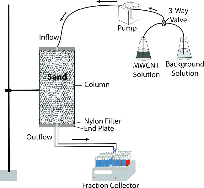 Figure 1. Overview of column experiment setup for transport of nanoparticle through porous media.
Please click here to view a larger version of this figure.
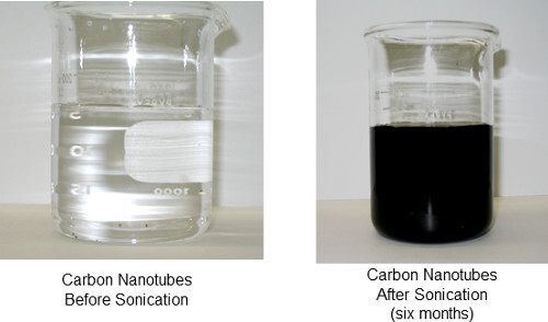 Figure 2. Stability test of functionalized carbon nanotubes.
Please click here to view a larger version of this figure.
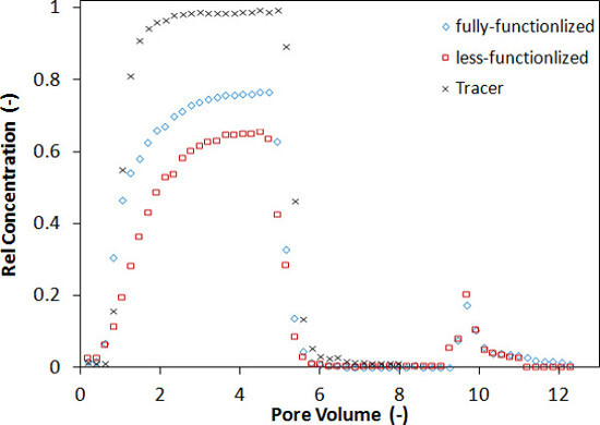 Figure 3.
Surface-modified MWCNTs eluted from the column (during phases 1, 2, and 3) packed with coarse sand for experimental condition of ionic strength: 2 mM; pH: 5; and flow rate: 15.5 m/d.
Please click here to view a larger version of this figure.
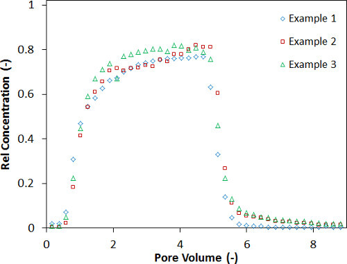 Figure 4.
Examples of breakthrough curves for eluted MWCNTs functionalized at three different batches at same experimental condition.
Please click here to view a larger version of this figure.
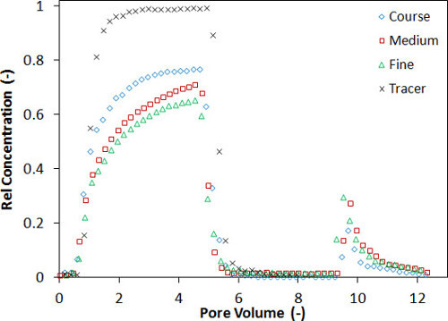 Figure 5.
MWCNTs eluted from the column (during phases 1, 2, and 3) for different porous media grain size for experimental condition of ionic strength: 2 mM; pH: 5; and flow rate: 15.5 m/d.
Please click here to view a larger version of this figure.
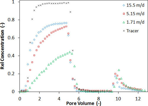 Figure 6.
MWCNTs eluted from the column (during phases 1, 2, and 3) for different flow rates for experimental condition of ionic strength: 2 mM; pH: 5; and sand size: 300 µm.
Please click here to view a larger version of this figure.
| pH | Ionic strength (mM) | Grain size (µm) | Flow rate (ml/min) | Pore water velocity (m/day) |
| 5 | 2 | 300 | 2 | 15.5 |
| 5 | 2 | 300 | 2 | 15 |
| 5 | 2 | 211 | 2 | 15.5 |
| 5 | 2 | 150 | 2 | 15.5 |
| 5 | 2 | 300 | 0.66 | 5.17 |
| 5 | 2 | 300 | 0.22 | 1.71 |
Table 1. Summary of experimental condition for column experiments.
Discussion
Effect of MWCNT Functionalization
As Figure 2 confirms the stability of functionalized MWCNTs, the observed difference in eluted volume of MWCNT was due to functionalization and particularly due to the addition of carboxyl (-COOH) groups to the surface of the MWCNTs (Figures 3 and 4). In the similar functionalization process, the presence of oxygen was confirmed by X-ray photoelectron spectroscopy14. It has been found earlier that the addition of surfactant to nanoparticle surfaces stabilizes their suspension and reduces aggregation23. According to other independent studies, aggregation from the absence of energy barriers between the particles increases the size and deposition rate of nanoparticle aggregates and contributes to the occurrence of physical straining18,23-25. Therefore, aggregation is likely to have increased the deposition and retention of the less functionalized (more hydrophobic) MWCNTs in this study. It has been proven that the retention of hydrophobic colloids in porous media is higher than that of hydrophilic colloids, and solid-water and air-water-solid interfaces are suggested as the main site of deposition24,26,27. In addition, the retention of nanoparticles increases with surface hydrophobicity28, which agrees with the current experimental observations, since less functionalized MWCNTs are more hydrophobic compared to (fully) functionalized MWCNTs. But the extent of functionalization of MWCNTs are method specific, being followed in the lab, which can produce an erroneous result during a column studies for an accurate prediction of transported nanoparticle in the porous media.
Experimental Condition in the Column Transport Studies
As the solution chemistry was same in all three cases in Figure 5, physical straining should explain the deposition differences between these three experiments. Bradford et al.29 found that grain-to-grain straining typically occurs when the ratio of particle diameter to collector diameter is greater than 0.05. However, in another study, Bradford et al.30 found that such straining could happen when the ratio is as low as 0.003. Since MWCNTs are cylindrical particles, the ratio was calculated twice using both particle diameter and length. In a previous study on MWCNTs, Liu et al.16 found that the critical value for MWCNTs was 0.003 µm for diameter and 0.011 nm for length to initiate the physical straining. As specified by the manufacturer, the mean length and diameter of the MWCNTs used in this study were 15 µm and 40 nm, respectively. Using these values, the ratios of MWCNT length to sand grain diameter are above the critical value for all sands (0.05, 0.07 and 0.1), but the ratios of MWCNT diameter to sand grain diameter are all below the critical value (0.00013, 0.00018 and 0.00027) as compared to previous studies22. Mattison et al.14 suggested that straining could be one of the major mechanisms when the ionic strength is low. In this study, the effluent MWCNTs mass (from phases 1 and 2) shows that larger grain sizes led to less deposition. This may suggest that more MWCNTs were strained for smaller sand grain sizes. The differences in the amount of particle retention for different grain sizes should at least partly be explainable by differences in grain-to-grain straining, but this may not be the sole reason during a column transport studies. So a well-established column transport study using a range of porous media grain sizes is important for the comparison of similar studies conducted in different literature and for the application of such finding in the field.
Retention of MWCNTs due to Flow Pattern
The variation in flow rate during any column studies can be very critical for nanoparticle transport studies. The example of this effect has been demonstrated in this study as well as compared with other similar studies in Sharma et al.22. Figure 6 showed that the mobility of MWCNTs was strongly dependent on flow rate, i.e., higher retention with decrease in flow rate, which is consistent with previous studies14,16. The impact of flow variation in MWCNT transport studies has been discussed in Sharma et al.22. Similarly the study highlights the importance of flow pattern in the column transport experiments in addition to the surface properties of nanoparticle and background solution chemistry, as the fluctuation and change in flow pattern are common in nature that can also impact the transport and retention of MWCNTs through soil and groundwater.
Practical Implications
It can be concluded from this study that the functionalization of MWCNT is an important process to understand the fate and transport of MWCNT in porous media. The steps taken during the surface modification process on MWCNT can be critical for the total retention of these nanoparticles during a column studies as demonstrated in this study and also observed in literature. Therefore, a well-documented guideline of surface modification of MWCNT is necessary in order to compare the impact of physical and chemical parameters for correct estimation of transport and retention of these nanoparticles in soil pores. The systematic steps followed in this study during the preparation of sand packed column experiment could further be useful for well controlled laboratory scale studies for nanoparticle transport estimation and be comparable for large scale application of such findings.
Disclosures
The authors declare that they have no competing financial interests.
Acknowledgments
The authors would like to acknowledge the support from the Department of Earth Sciences, Uppsala University for supporting part of this research.
References
- Maynard AD, et al. Safe handling of nanotechnology. Nature. 2006;444:267–269. doi: 10.1038/444267a. [DOI] [PubMed] [Google Scholar]
- Mauter M, Elimelech M. Environmental applications of carbon-based nanomaterials. Environ. Sci. Technol. 2008;42(16):5843–5859. doi: 10.1021/es8006904. [DOI] [PubMed] [Google Scholar]
- Darka-Kagy K, Khodadoust AP, Reddy KR. Reactivity of aluminum lactate-modified nanoscale iron particles with pentachlorophenol in soils. Environ. Eng. Sci. 2010;27(10):861–869. doi: 10.1016/j.jhazmat.2010.06.012. [DOI] [PubMed] [Google Scholar]
- Lin D, et al. Fate and transport of engineered nanomaterials in the environment. J. Environ. Qual. 2010;39(6):1896–1908. doi: 10.2134/jeq2009.0423. [DOI] [PubMed] [Google Scholar]
- Petersen EJ, et al. Potential release pathways, environmental fate, and ecological risks of carbon nanotubes. Environ. Sci. Technol. 2011;45(23):9837–9856. doi: 10.1021/es201579y. [DOI] [PubMed] [Google Scholar]
- Wiesner M, Bottero JY. Environmental nanotechnology. The Blacklick, OH: McGraw-Hill Companies; 2007. [Google Scholar]
- Klaine SJ, et al. Nanomaterials in the environment: Behavior, fate, bioavailability, and effects. Environ. Toxicol. Chem. 2008;27(9):1825–1851. doi: 10.1897/08-090.1. [DOI] [PubMed] [Google Scholar]
- Wang C, et al. Toxicity effects of four typical nanomaterials on the growth of Escherichia coli, Bacillus subtilis and Agrobacterium tumefaciens. Environ. Earth Sci. 2012;65(6):1643–1649. [Google Scholar]
- Shen M, et al. Polyethyleneimine mediated functionalization of multi-walled carbon nanotubes: Synthesis characterization, and in vitro toxicity assay. J. Phys. Chem. C. 2009;113(8):3718–3724. [Google Scholar]
- Sahithi K, et al. Polymeric conposites containing carbon nanotubes for bone tissue engineering. Int. J. Biol. Marcomol. 2010;46(3):281–283. doi: 10.1016/j.ijbiomac.2010.01.006. [DOI] [PubMed] [Google Scholar]
- Petersen E, Huang Q, Weber W. Bioaccumulation of radio-labeled carbon nanotubes by Eisnia Foetida. Environ. Sci. Technol. 2008;42(8):3718–3724. doi: 10.1021/es071366f. [DOI] [PubMed] [Google Scholar]
- Gottschalk F, et al. Modeled Enrionmental concentrations of engineered nanomaterials for different regions. Enrviron. Sci. Technol. 2009;43(24):9216–9222. doi: 10.1021/es9015553. [DOI] [PubMed] [Google Scholar]
- Liu X, et al. et al.Mobility of multiwalled carbon nanotubes in porous media.Environ. Sci. Technol. 2009;43(21):8153–8158. doi: 10.1021/es901340d. [DOI] [PubMed] [Google Scholar]
- Tian Y, Gao B, Ziegler KJ. High mobility of SDBS-dispersed single-walled carbon nanotubes in saturated and unsaturated porous. J. Hazard. Mater. 2011;186(2-3):1766–1772. doi: 10.1016/j.jhazmat.2010.12.072. [DOI] [PubMed] [Google Scholar]
- Mattison NT, et al. Impact of porous media grain size on the transport of multi-walled carbon nanotubes. Environ. Sci. Technol. 2011;45(22):9765–9775. doi: 10.1021/es2017076. [DOI] [PubMed] [Google Scholar]
- Kasel D, et al. Limited transport of functionlized multi-walled carbon nanotubes in two natural soils. Environ. Pollution. 2013;180:152–158. doi: 10.1016/j.envpol.2013.05.031. [DOI] [PubMed] [Google Scholar]
- Yu S, et al. Effects of humic acid and Tween-80 on behavior of decabromodiphenyl ether in soil columns. Environ. Earth Sci. 2013;69(5):1523–1528. [Google Scholar]
- Jaisi DP, et al. Transport of single-walled carbon nanotubes in porous media: filtration mechanisms and reversibility. Environ. Sci. Technol. 2008;42(22):8317–8323. doi: 10.1021/es801641v. [DOI] [PubMed] [Google Scholar]
- Tiraferri A, Tosco T, Sethi R. Transport and retention of microparticles in packed sand columns at low and intermediate ionic strengths: experiments and mathematical modeling. Environ. Earth Sci. 2011;63(4):847–859. [Google Scholar]
- Tian Y, et al. Deposition and transport of functionalized carbon nanotubes in water-saturated sand columns. J. Hazard. Mater. 2012;213-214:265–272. doi: 10.1016/j.jhazmat.2012.01.088. [DOI] [PubMed] [Google Scholar]
- Mekonen A, Sharma P, Fagerlund F. Transport and mobilization of multiwall carbon nanotubes in quartz sand under varying saturation. Environ. Earth Sci. 2014;71(8):3751–3760. [Google Scholar]
- Sharma P, Bao D, Fagerlund F. Deposition and mobilization of functionalized multiwall carbon nanotubes in saturated porous media: effect of grain size, flow velocity and solution chemistry. Environ. Earth Sci. 2014.
- Phenrat T, Lowry GV, Hotze EM. Nanoparticle aggregation: challenges to understanding transport and reactivity in the environment. J. Environ. Qual. 2010;39(6):1909–1924. doi: 10.2134/jeq2009.0462. [DOI] [PubMed] [Google Scholar]
- Crist JT, et al. Transport and retention mechanisms of colloids in partially saturated porous media. Vadose Zone J. 2005;4(1):184–195. [Google Scholar]
- Jaisi DP, Elimelech M. Single-walled carbon nanotubes exhibit limited transport in soil columns. Environ. Sci. Technol. 2009;43(24):9161–9166. doi: 10.1021/es901927y. [DOI] [PubMed] [Google Scholar]
- Corapcioglu MY, Choi H. Modeling colloid transport in unsaturated porous media and validation with laboratory column data. Water Resour. Res. 1996;32(12):3437–3449. [Google Scholar]
- Wan J, Wilson JL. Colloid transport in unsaturated porous media. Water Resour. Res. 1994;30(4):857–864. [Google Scholar]
- Wan J, Wilson JL. Visualization of the role of the gas-water interface on the fate and transport of colloids in porous media. Water Resour. Res. 1994;30(1):11–24. [Google Scholar]
- Bradford SA, et al. Physical factors affecting the transport and fate of colloids in saturated porous media. Water Resour. Res. 2002;38(12) [Google Scholar]
- Bradford SA, Torkzaban S, Walker SL. Coupling of physical and chemical mechanisms of colloid straining in saturated porous media. Water Res. 2007;41(13):3012–3024. doi: 10.1016/j.watres.2007.03.030. [DOI] [PubMed] [Google Scholar]


