SUMMARY
Purpose.
The aim of this paper was to describe the CEREC 3 chairside system, providing the clinicians a detailed analysis of the whole digital workflow. Benefits and limitations of this technology compared with the conventional prosthetic work-flow were also highlighted and discussed.
Materials and methods.
Clinical procedures (tooth preparation, impression taking, adhesive luting), operational components and their capabilities as well as restorative materials used with CEREC 3 chairside system were reported.
Results.
The CEREC system has shown many positive aspects that make easier, faster and less expensive the prosthetic workflow. The operator-dependent errors are minimized compared to the conventional prosthetic protocol. Furthermore, a better acceptance level for the impression procedure has shown by the patients. The only drawback could be the subgingival placement of the margins compared with the supra/juxta gingival margins, since more time was required for the impression taking as well as the adhesive luting phase. The biocopy project seemed to be the best tool to obtain functionalized surfaces and keep unchanged gnathological data. Material selection was related to type of restoration.
Conclusions.
The evidence of our clinical practice suggests that CEREC 3 chairside system allows to produce highly aesthetic and reliable restorations in a single visit, while minimizing costs and patient discomfort during prosthetic treatment. However improvements in materials and technologies are needed in order to overcome the actual drawbacks.
Keywords: adhesive luting, all-ceramic, CAD/CAM, CEREC, chairside, optical impression, metal-free
Introduction
The use of computer-aided design computer-aided manufacturing (CAD/CAM) systems in dentistry has increased dramatically during the last decade thanks to the fast development of digital computer technology. CAD/CAM approach has been introduced in dentistry as a precise, efficient, accurate and error-free tool to produce high-quality dental restorations, as opposed to the traditional way of manual manufacture, which is prone to numerous subjective errors (1). Nowadays CAD/CAM systems may be categorized as either chairside or laboratory systems. The first commercially available CAD/CAM system has been CEREC, developed by Mormann and Brandestini. This chairside system allows the clinicians in private offices to independently design and also machine dental ceramic restorations in matter of hours, enabling reconstruction during single visit (2).
Since its introduction to the dental field in 1985 as the CEREC 1, this system has evolved through a series of software and hardware upgrades up to the CEREC 3D.
The CEREC 1 allowed for a limited 2-dimensional (2-D) view of the scanned images and was able to fabricate exclusively inlays for immediate cementation (3).
The evolution of supportive computer technology over time has led to a three dimensional (3D) design program. An immediate feedback on the 3D model during the planning phase has made this technology more intuitive and user friendly, improving quality as well as the clinical work flows of chairside system use.
Furthermore the current CEREC 3 system has expanded the restorative capabilities significantly and can fabricate inlays, onlays, veneers, crowns, as well as three unit bridges and custom lithium disilicate implant abutments.
Modern technologies have improved the system performance, but the workflow was not modified. An optical impression is taken by means a scanning device in order to capture complete detail of the teeth and supporting soft-tissue structures (4).
The images of intraorally scanned optical impressions are visualized on the computer monitor in real time and can then be further processed by the clinician interactively (CAD) (5). The software allows to mark the margins, digitally design virtual wax-up proposals of the restoration, adjust occlusal contacts and calibrate the proximal contact areas. Additional features such as the automatic occlusal adjustment, the virtual articulator and the digital smile design (DSD) are provided by the last upgrade. The final data are sent to the computer-controlled milling unit (CAM) for a metal-free monoblock milling. The restoration undergoes a finishing phase (coloring, glazing, polishing) and is then ready for an adhesive luting.
To our current knowledge, only limited clinical data about CEREC CAD/CAM chairside system have been reported. It should be noticed that almost 30 years have passed since it was born and the rapid advance of the technology over this period have made the devices, the materials as well as the dedicated work protocols more efficient and reliable. However skepticism and a lack of knowledge about this system are still present among clinicians. The purpose of this paper is to provide a useful evaluation tool, with a detailed description of the system, highlighting and discussing its potential and its limits.
Materials and methods
Tooth preparation and milling unit capability
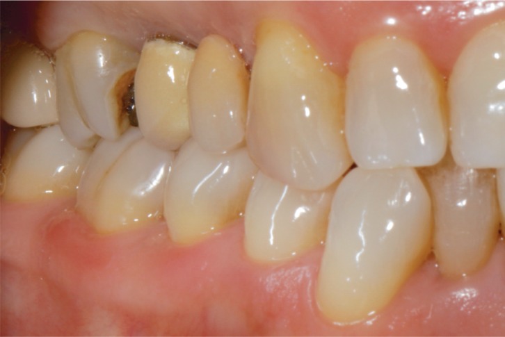
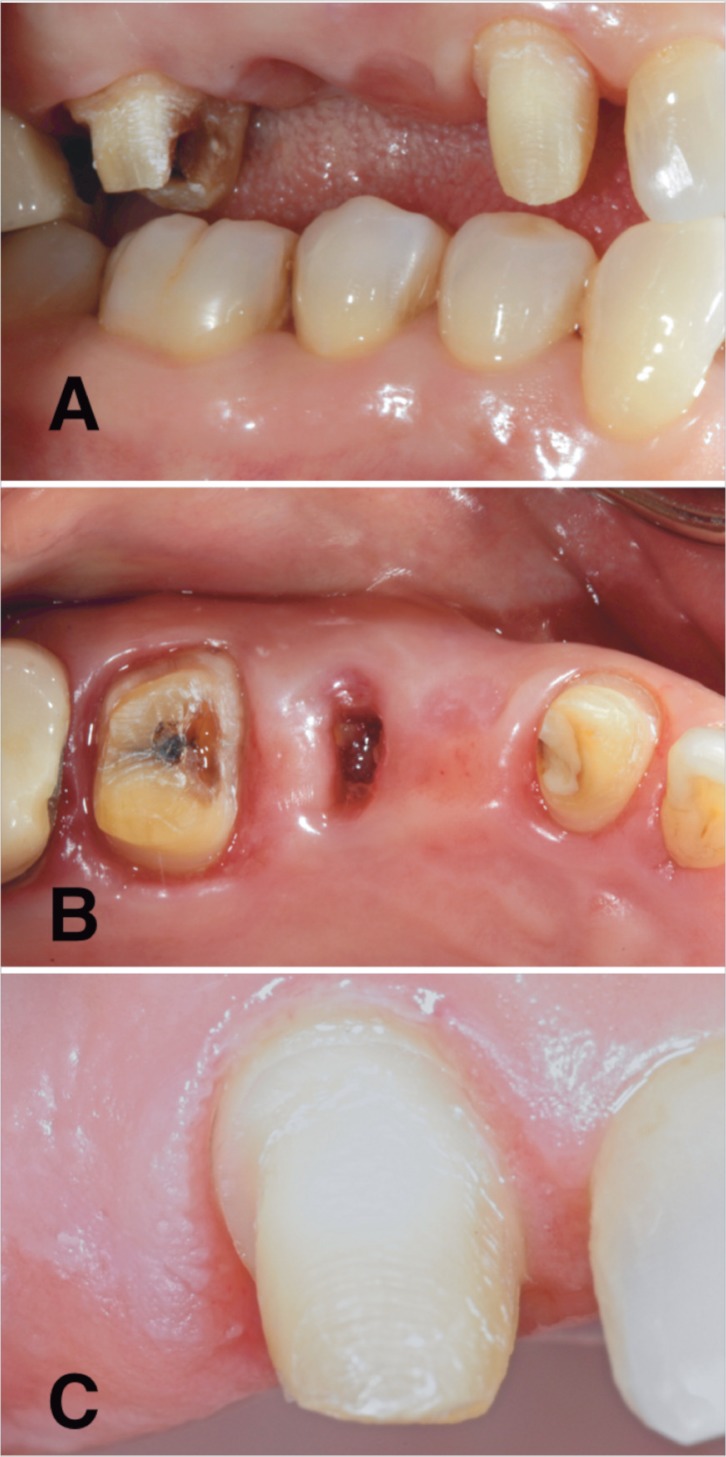
The importance of tooth tissue preservation has led to the development of minimal invasive/ultraconservative dentistry. This concept has been supported by continuous introduction of new metal-free adhesive materials, which offer clinical reliability due to enhanced physical and mechanical properties (6). The amount of tooth reduction depends on the achievement of the right thickness for the prosthetic material (7). Aesthetics and structural durability are obtained with minimum thickness, since these materials do not require the presence of a metal substructure (8). The clinician is not compelled to sub-gingival margin placement, due to the perfect color correspondence between the tooth and the restorative material together with the absence of metal edges. A supra/juxta gingival margin placement is recommended in order to facilitate the tooth exposure and the work field isolation during the optical impression and the luting procedure, respectively. The use of the adhesive luting modifies the resistance form (height and width) as well as retention form (convergence angle) of the traditional preparation guidelines, avoiding weakening the tooth unnecessarily (9, 10). The preparation features must correspond primarily to the optical scanner potentiality as well as to the milling machine capabilities, which are related to the shape and dimension of the milling instruments (step bur 10 for the fitting surface, cylinder pointed bur for the occlusal surface). Rounded angles should be preferred to tight corners in order to improve load distribution through the material and avoid stress peaks (11, 12). Undercut areas as well as small spikes or irregular surfaces on the preparation margin should be avoided (Figs. 1, 2 A, B, C).
Figure 1.
Lateral view of the initial clinical situation. Tooth N. 16 showed a substantial loss of structure resulting from caries; tooth N. 15 needed to be extracted due to a periodontal lesion.
Figure 2 A, B, C.
Teeth preparation. Supra-gingival (tooth N. 13) and juxta-gingival (tooth N. 16) margin placement. A) Lateral view. B) Occlusal view. C) A higher magnification of the preparation (tooth N. 13).
According to the above, the principles of the tooth preparation for a full crown restoration would provide: a height not exceeding 10.5 mm, a minimum width of 1.0 mm, a circular minimal round shoulder of 0.8 −1 mm, a 6° convergence angle and a 1.2–1.5 mm occlusal reduction.
Restoration design
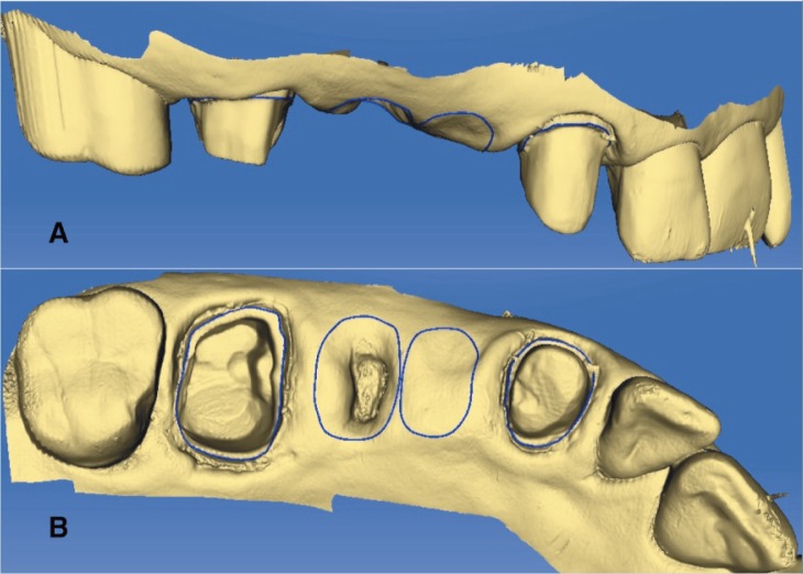
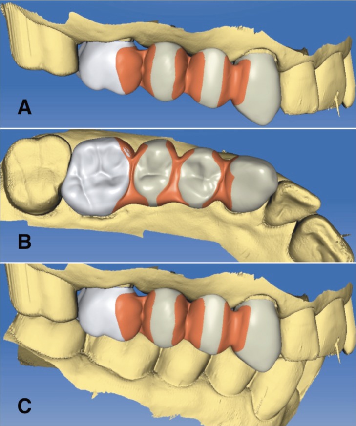
The software guides the clinician step by step during the project. The material and the type of restoration (veneer, inlay, onlay, overlay, crown, bridge, maryland or abutment) can be choose (13, 14). The software allows to select between three options for the design of the restoration: bioreference, biocopy or biogeneric. In the bioreference project, the design of the restoration incorporates the anatomical features of the corresponding contra-lateral tooth, if it is present. The biocopy project reproduces the anatomy of the tooth before the preparation or the temporary restoration, in order to keep unchanged aesthetics and function. In the biogeneric project, the software reads the morphology patient’s dentition to predict the right form and function. The optical impression provides data of the both arches and those relevant to their occlusal relationship. Once the virtual model is developed, the clinician can select the insertion axis and mark the margins (Fig. 3 A, B). According to the type of project and the operator indications, the software generates a restoration (Fig. 4 A, B, C). Several tools allow to perform all the changes, which are required such as position, shape, proximal and occlusal contacts. Before data are sent to the milling machine, the software allows to virtually place the restoration into the block material for the best milling position, which is very useful when multishaded blocks are used.
Figure 3 A, B.
CAD model generated by the optical impression. Determination of the preparation line. A) Screenshot of the lateral view. B) Screenshot of the occlusal view.
Figure 4 A, B, C.
Processing of the bridge in the CAD module. Manual modification of the size and shape of the connector regions with specific toolbar. A) Screenshot of the lateral view. B) Screen-shot of the occlusal view. C) Screenshot of the inter-occlusal relationship.
Restorative materials
Innovative materials have been proposed by industry in order to satisfy the increased demand for restorations which are indistinguishable from the neighboring dentition over time (15).
Therefore, the first task for such metal-free systems is to provide enhanced aesthetics, but they must also have biomechanical features that ensure longevity similar to metal-ceramic restorations.
These materials are fabricated, in ingot form, with reproducible and constant manufacturing processes. The mechanical and physical properties allow to these materials to be milled rapidly, resist machining damage, be finished easily (for example, polished, stained or glazed) before placement and be functionally stable.
The lack of metal core provides two benefits: highly aesthetic appearance and minimally-invasive approach. Metal-free restorations in fact can resemble natural tooth structure in terms of colour and light translucency, since no light transmission is blocked by the dark substructure (16). Optical continuity from tooth structure to restoration is further improved by the bonding mechanism (17, 18). The second advantage is the conservative tooth preparation, since the thickness for the metal is no more needed (19, 20). Nowadays several materials are available for CEREC chairside system (21) (Tab. 1).
Table 1.
Materials available to use with CEREC chairside system.
| Material | Manufacturer | Composition | Veneers | Crowns | Inlays | Onlays | Bridges | Introduction |
|---|---|---|---|---|---|---|---|---|
| Mark II | Vita Zahnfabrik | Feldspathic porcelain | √ | √ | √ | √ | 1991 | |
| Enamic | Vita Zahnfabrik | Ceramic resin hybrid | √ | √ | √ | √ | 2013 | |
| Empress CAD | Ivoclar Vivadent | Leucite-reinforced porcelain | √ | √ | √ | √ | 2006 | |
| E.max | Ivoclar Vivadent | Lithium Disilicate | √ | √ | √ | √ | 2006 | |
| Lava Ultimate | 3M Espe | Nano Ceramic/Resin | √ | √ | √ | √ | 2012 | |
| CEREC blocks | Vita Zahnfabrik | Feldspathic porcelain | √ | √ | √ | √ | 2007 | |
| Paradigm C | 3M Espe | Leucite-reinforced porcelain | √ | √ | √ | √ | 2006 | |
| Paradigm MZ100 | 3M Espe | Composite resin | √ | √ | √ | √ | 2000 | |
| CAD-Temp | Vita Zahnfabrik | Temporary Composite Resin | √ | √ | 2007 | |||
| Telio CAD | Ivoclar | Temporary Composite Resin | √ | √ | 2009 | |||
| ProCad | Ivoclar Vivadent | Feldspathic Porcelain | √ | √ | √ | √ | 1998 | |
| Celtra duo | Dentsply | Zirconia reinforced lithium silicate | √ | √ | √ | √ | 2013 | |
| Suprinity | Vita Zahnfabrik | Zirconia reinforced lithium silicate | √ | √ | √ | √ | 2013 |
Lithium disilicate
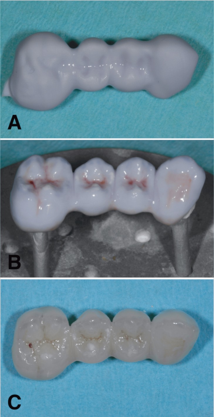
IPS e.max CAD (Ivoclar Vivadent AG, Schaan, Liechtenstein) is a lithium disilicate glass-ceramic for CAD/CAM applications, the blocks are produced by massive casting of transparent glass ingots, a continuous manufacturing process based on glass technology is utilized to prevent the formation of defects (pores, accumulation of pigments and so forth) in the bulk of the ingot. Partial crystallization process leads to a formation of lithium metasilicate (Li2SiO3) crystal, which are responsible for the material’s optimal processing properties, edge stability, and relatively high strength (Fig. 5 A, B). After the milling procedure, the restorations are tempered and lithium disilicate crystals are formed, which impart the ceramic object with desired high strength (Fig. 5 C). A 2010 study by Guess et al. tested monolithic CAD/CAM lithium disilicate and hand layer-veneered zirconia all-ceramic crowns and found that using IPS e.max CAD resulted in fatigue resistant crowns, while hand layer veneered zirconia crowns revealed early veneer failures (22).
Figure 5 A, B, C.
A) The IPS e.max CAD block was milled in the “blue,” softer state. This allows the milling unit to mill this material without too much effort. B) After milling, the crown was customized using laboratory burs and was stained and glazed. C) After placing the restoration in the oven for approximately 15 minutes, the final shade was shown.
Leucite glass-ceramic
Pro CAD was the first available leucite-reinforced glass-ceramic CAD/CAM block (13). To date it has been replaced to the current IPS Empress CAD (Ivoclar Vivadent AG, Schaan, Liechtenstein), that is a leucite glass-ceramic of the SiO2-Al2-O3-K2O material systems with leucite crystal ranging from 5 to 10 µm in size (14). The leucite crystals increase the material strength and slow down or deflect crack propagation, while the crystalline phase absorbs fracture energy. During the block production, the powder is pressed automatically in order to obtain maximum homogeneity. The difference in the thermal expansion coefficient between the glass phase and the crystalline phase, as well as the cooling process following sintering phase, improve resistance and flexural strength (160 Mpa).
Paradigm C (3M ESPE AG, Seefeld, Germany) is a glass ceramic block made out of a two phase leucite ceramic available in six different classic shades (A1, A2, A3, A3.5, B3, Bleach) and is provided in five different block sizes. Leucite crystals (approximately 30% ± 5%) are generated within the blocks after a special heat treatment process. Therefore, any further crystallization step is not needed.
Feldspathic ceramic
VITABLOCS Mark II (VITA Zahnfabrik, Bad Sackingen, Germany) is a monocromatic feldspathic ceramic and its abrasion coefficient is fully comparable to the tooth enamel. It is recommended for inlays, onlays, veneers, posterior and anterior crowns. This feldspathic ceramic is now also available as TriLuxe and TriLuxe Forte, which are made of three and four layers with different shade intensity respectively. These multi-layer blocks assure restorations featuring natural shade transition. The most recent material developed is the VITABLOCS RealLife, which is recommended for highly aesthetic anterior restorations, due to its dentine core and enamel coat. This feature mimics the curved shade transitions between dentine and incisal edge according to natural tooth structure. The same features are also provided by another material, which is called Cerec block (Sirona, Bensheim, Germany).
Hybrid ceramic
ENAMIC (VITA Zahnfabrik, Bad Sackingen, Germany) is a newly-developed hybrid material that combines the positive characteristics of proven ceramic materials with those of the composite materials. The pores in the structure-sintered ceramic matrix are filled with a polymer material. The mass percentage is 86 wt% and 14 wt% for the inorganic ceramic part and the organic polymer part respectively. This material combination increases fracture strength and CAD/CAM handling compared with traditional ceramics.
Lava Ultimate (3M ESPE AG, Seefeld, Germany) is a resin nanoceramic, which is made of nanoceramic components (approx. 80%) embedded in a polimer matrix at elevated polymerization. This innovative material can be characterized and repaired by methacrylate based light curing both intraorally that extraorally.
Resins
Paradigm MZ 100 (3M/ESPE AG, Seefeld, Germany) is a definitive, aesthetic and radiopaque material, that under optimized process conditions, assures a deep cure due to a high degree of crosslinking. This process improves physical properties and clinical performance.
Telio CAD (Ivoclar Vivadent AG, Schaan, Liechtenstein) are cross-linked PMMA blocks for the fabrication of long-term temporaries (max 12 months). In addition stains and/or layering materials are provided to achieve final aesthetic optimizations.
CAD Temp (VITA Zahnfabrik, Bad Sackingen, Germany) block consists of a fiber-free and cross-linked acrylate polymer with microparticle filler, that is called MRP (microfiller reinforced poliacrylic). Inorganic microfillers are polymerised into the network and a completely homogeneous, methyl-methacrylate free material is obtained in order to increase material quality and abrasion resistance in long term temporaries.
Lithium silicate with zirconia
Suprinty (VITA Zahnfabrik, Bad Sackingen, Germany) is a lithium silicate ceramic (ZLS) enriched with zirconia (approx. 10 wt%). This new glass ceramic features a special fine-grained and homogeneous structure, which guarantees excellent material quality and consistent high load capacity. Thanks to the excellent translucency, fluorescence and opalescence of this new glass ceramic material, VITA SUPRINITY provides excellent aesthetic properties.
Celtra Duo (Dentsply, PA, U.S.) is another zirconia-reinforced lithium silicate (ZLS). This material exhibits increased flexural strength and chameleon-like aesthetics compared with lithium disilicate. After the milling process restorations are yet correctly shaded, with no additional crystallization step required.
Adhesive luting
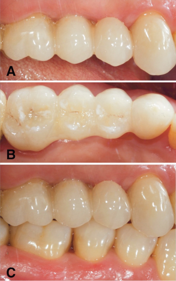
Adhesive cementation has been clinically proven to be a suitable procedure for the permanent seating of indirect restorations, but a restricted protocol must be used by the clinician (23). A careful isolation by means rubber dam and retraction cords is required in order to maximize the predictability of the adhesive luting process. After the temporary restoration has been removed, the cavity or the prepared tooth needs to be cleaned. Subsequently, the restoration can be tried in e.g. using a try-in paste. After try-in, the bonding surfaces of the restorations require cleaning again prior to pre-treating or conditioning them with suitable agents in order to create significant bond strength between tooth structure and restorations. Contamination of restoration surfaces is unavoidable during the milling process as well as the tryin. In fact, during milling, the work area is flooded by a cooling liquid which is typically 90 to 95% water and 5 to 10% machine coolant (lubricating oils, greases and metal particulates). During the try-in, restoration surfaces are contaminated by saliva proteins and lipids (24). Among various cleaning materials and/or procedures (water, isopropanol, phosphoric acid or corundum blasting), the most reliable seems to be an alkaline suspension of zirconium oxide particles (Ivoclean, Ivoclar Vivadent AG, Schaan, Liechtenstein). This cleaning paste provides for effectively cleaning saliva-contaminated bonding surfaces of restorations and its universal indication makes it possible for use in dental restorative materials including glass ceramics, zirconium oxide ceramics, aluminum oxide ceramics, precious metal alloys, base metal alloys and lab-fabricated composite restorations. Thus following try-in of the restoration, water spray is used to thoroughly rinse the restoration, which is then dried with oil-free air and a layer of the cleaning paste is applied to the entire bonding surface of the restoration. After 20 seconds the restoration is then thoroughly rinsed using water spray and dried with oil-free air. The restoration surface is etched with hydrofluoric acid in order to create a micro-retentive etching pattern, which enlarges the bonding surface and then placed in the ultrasonic bath before the silanization (25–28). The tooth surface is sandblasted in order to create a micro porosity and an adhesive system is applied (29). Finally the luting agent is applied and the restoration is seated on the preparation (Fig. 6 A, B, C). The residual cement is removed and the polymerization can be performed (Fig. 7 A, B). Most of dual curing cements can be used with metal-free restoration, however, depending on the restoration thickness, a light curing composite can be also used (8, 30).
Figure 6 A, B, C.
Placement of the lithium disilicate bridge after try-in. Only limited adjustments were needed prior to adhesive luting. A) Lateral view. B) Occlusal view. C) Inter-occlusal relationship.
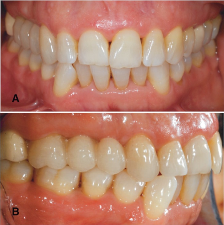
Figure 7 A, B.
Monolithic CAD/CAM lithium disilicate glass-ceramic bridge (IPS e.max CAD, Ivoclar Vivadent AG, Schaan, Liechtenstein) at the one-year recall. The perfect soft and hard tissue integration made the restoration indistinguishable from the neighboring dentition and the patient was extremely pleased with the final result. A) Frontal view. B) Lateral view.
Results
Table 2 shows the benefits and the potential drawbacks of the chairside system. Each step of the clinical workflow as well as the devices and their capabilities were analyzed.
Table 2.
Benefits and drawbacks of the chairside system.
| Operative Step | Benefits | Drawbacks |
|---|---|---|
| Tooth Preparation | Higher simplicity, due to margin positioning: supra or juxta gingival Micro-invasive preparations: lower removal of dental tissue, i.e. less time and decreased risk of pulpal necrosis |
The preparation must be appropriate to the capacity of the milling unit |
| No needs for traditional retention design (height, width and taper) due to adhesive luting | Sub-gingival margins: working field isolation, adhesion procedures, impression taking, final positioning of the restoration | |
| Preparation Time Saving Fast and efficient healing of the soft tissue due to superficial and atraumatic positioning of the margins No need for provisional restorations |
||
|
| ||
| Milling Unit Capacity | Shortened Production time Several materials available |
Influence of the tooth preparation design |
|
| ||
| Impression | Faster than traditional procedure | Sub-gingival margins: coronal relocation of the margin, surgical exposure of the margin, clinical crown lengthening |
| Costs: no need for impression material Better acceptance of the procedure by the patient due to the absence of the impression material Higher simplicity in the gingival retraction operations due to the superficial positioning of the finishing line Immediate taking: no need for soft tissue healing due to superficial and atraumatic positioning of the margins Improved communication and patient involvement thanks to the digital interface No need for any powder |
||
|
| ||
| Design | Immediate visualization of the tooth preparation by the clinician Possibility for a prompt correction (axis, taper, thickness, finish line) Margin marking Selection of the insertion axis Choice of the pattern, the extension and the pressure of occlusal contacts Setting of the design, the extension and the pressure of proximal contact area |
Absence of gnathologic data and prosthetic functionalization |
|
| ||
| Materials | Wide selection High quality standardization due to reproducible and constant manufacturing process High aesthetics High precision levels High biocompatibility Shortened milling time Costs |
Type of restoration |
|
| ||
| Adhesive Luting | Choice of the cement shade according to tooth and restorative material colours | Procedure Time Post-operative sensitivity Perfect isolation of working field Sub-gingival margins Costs |
Discussion
CAD/CAM dentistry has evolved from its rudimentary beginnings to a viable chairside technology that allows the clinicians to treat patients in a single visit, without need of a second appointment (31). Sirona CEREC chairside CAD/CAM system has spread slowly, but continuously between clinicians around the world since its introduction. Certainly the approach with a new technology and its learning curve, costs, the limited number of dedicated materials as well as the range of uses, the lack of long-term follow-up have made dentists skeptical and suspicious of this system. However, clinicians have had to face the increasing demands of patients for fast, highly aesthetic and minimally invasive treatments. Thanks to technological developments of the last three decades, the initial limits of the chairside system have been overcome. To date it is faster, more intuitive and user friendly (4). The range of restorative solutions is expanded and covers most of clinical needs. New materials are daily developed and supplied by material manufacturers, which have increased their research, since they have noticed the potential profit, as the number of CEREC users has grown (32). The accuracy in acquisition and milling processes, is constantly improved through continuous software and hardware upgrades and several in vitro studies as well as clinical long-term in vivo evaluations have been reported in literature, in order to confirm the reliability of this technology (10, 22, 33, 34). With almost 40,000 users worldwide, today this system could and should be considered a viable alternative to traditional procedures. The experience gained in our clinical practice allowed for a careful evaluation of the CEREC system and a comparison of each step of its workflow (Tab. 3) with the traditional procedures.
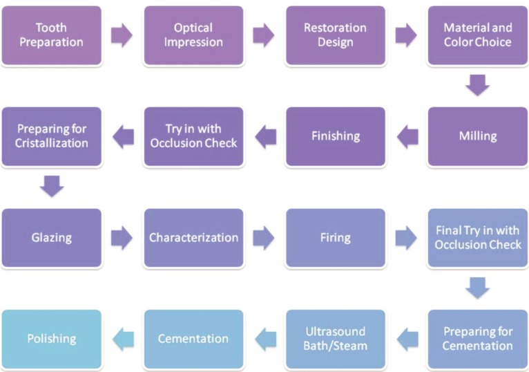
Table 3.
Cerec Chairside Workflow.
A correct prosthetic rehabilitation always starts from a correct diagnosis. In this paper, the following operative steps have been analyzed: tooth preparation, impression taking, digital design of the restoration, restoration production and luting procedure.
The preparation design is closely dependent on the type restoration and restorative material, the capabilities of the milling machine and the type of cementation. The lack of a metal core and the adhesive luting procedure positively affect the amount of tooth reduction, which led to several benefits for both the prosthodontist and the patient. In fact, even though the traditional prosthetic criteria (retention and resistance forms) are still the same, as suggested by the manufacturer, the preparations may be more conservative (35, 36) decreasing risk of pulpal necrosis. Indeed, the use of materials that can be adhesively bonded to the tooth could make the preparation easier and faster compared with the traditional one. High retention provided by the high bonding value between tooth and restoration allows to compensate the lack of operator skill when ideal height, width and taper of the preparation are not achieved (9, 10).
The reduced thickness of the restorative material and its enhanced aesthetics, allow to keep supra/juxta gingival margins, facilitating plaque removal for the patient (37) and impression and luting procedures for the clinician. Furthermore such margin depth avoids to hurt the soft tissue and the gingival growth on the finish line. Hence the traditional 21 day healing period and the tissue conditioning by the temporary restoration may be avoided. The lack of the provisional reduces the risk of pulpal stress and/or dentinal tubules contamination, whenever it is removed, due to excessive cleaning, drying or trauma (38). The risk for gingival irritation, due to difficulty in cleaning and maintenance the provisional, may be minimized (39–42).
As discussed above, a sub-gingival positioning of the margin could represent a limit for this system and the related materials. During impression a perfect displacement of the gingival tissue must be achieved, in order to place them away from the preparation margins and allow the optical scanner to capture all details (43). The traditional impression techniques exploit the impression material viscosity to further displace gingival tissues and read slightly covered surfaces (by gingiva, retraction cords or fluids). The optical scanner can detect only what is visible (44).
Furthermore, a perfect isolation of the operative field with a careful control of gingival hemorrhage and sulcular fluids is mandatory, due to the adhesive nature of the luting agents. Consequently, the use of temporary restorations may be suggested with sub-gingival margins, also when a single visit restoration is planned.
Digital impressions have the potential to be faster and easier than conventional impressions. Half-arch impressions takes 40 seconds while full-arch impressions take two minutes. The absence of the impression material results in a better acceptance of the procedure by the patient and in a cost reduction for the clinician (45). According to our experience as well as for the issues discussed above, preparation featuring subgingival margin might be difficult to read with optical scanner. In such cases traditional impression still represents the gold standard technique (46). Alternatively, margins could be relocated in a more coronally position, a surgical exposition as well as clinical crown lengthening may be performed before digital impression (47, 48). The 3D interface and the digital design of the restoration leads to many benefits (5). It allows the clinician to immediately evaluate the preparation, perform prompt correction if needed and take a new impression, limited to the changed areas (49).
According to opposing arch, muscle-skeletal relation, restorative material, type of restoration and occlusal pattern, extension and pressure of the occlusal contact as well as the proximal contact areas may be chosen with high accuracy (50, 51). This leads to a time saving for the restoration setting, since minimal adjustments are required. Although newest software allows to exploit the virtual articulator features, gnathological data (centric and eccentric contacts) which would enhance the prosthetic functionalization of the restoration, could be approximate (52). Certainly a biocopy project, which reproduces the anatomy of the tooth before the preparation or the temporary restoration, represents the best tool to obtain functionalized surfaces of the new restoration.
A wide selection of different materials is available for CEREC chairside system as shown in Table 1 (14). All these materials are produced with constant manufacturing processes which give high quality standardization (53). Mechanical and physical properties of these new machinable materials, such as fracture load, wear, marginal deterioration, and color stability have been improved during last years (54, 55).
Besides the obvious advantages that these materials offer such as aesthetic appearance, biocompatibility and durability, such materials also present with some disadvantages. All-ceramic restorations are prone to brittle fracture and abrasive wear of the opposing natural teeth while composite resin restorations are prone to wear, deterioration of surface finish, discoloration, fractures and color instability (56–58).
The long term success of the restoration is affected by the material selection. The clinical application of the material should be carefully evaluated, since some of the available materials do not cover all the restorative needs, preferring the restoration of small size (inlay, onlay, etc.). Regarding the luting procedure it should be noted that all materials and related techniques may be used. However, several studies reported that silanization and cementation using adhesive luting resins improved the mechanical properties of teeth as well as definitive restorations compared to non-adhesive cementation (25–28). Clinical experience suggests that the fracture rate of ceramic restorations decreases if the restorations are bonded with resin-based luting agents rather than cemented using zinc phosphate or conventional glass ionomer cements.
The adhesive luting requires a careful isolation, which ensures optimal fluid control and maximizes the predictability of procedure. Optimal luting conditions are difficult to obtain with subgingival preparations, as well as an effective removal of cement excess from the margins. Certainly the wide range of cement shades according to tooth and restorative material colours is a clear benefit for the aesthetic appearance enhancement with both supra-gingival and subgingival placement of the margins (59). Restorations can be more easily “integrated” with tooth structure, since the bonding mechanism can establish optical continuity from tooth structure to restoration.
As described above the chairside system evaluated in this paper seems to be a viable alternative to traditional procedures. Savings in time and labor may lead to potential cost reduction, improving quality and patient acceptance. As a new technology, the clinician needs to spend time and money on training. Furthermore clinicians without a large enough volume of restorations will have a difficult time making their investment pay off.
Conclusions
The evidence of our clinical practice suggests that CEREC chairside system is a useful tool for the clinician. The digital impression, the design software and the milling unit in the same office allow to produce highly aesthetic and reliable restorations in a single visit, while improving patient acceptance for the procedures. Both time and costs are reduced. Supra and juxta gingival margins seem to represent the ideal situation in order to exploit the full potentiality of the system. Material selection is still related to type of restoration. Further improvements in materials and technologies are needed in order to overcome the actual drawbacks.
Footnotes
Disclosure
All the authors state that they have no conflict of interest relevant to the content of the submission.
The contributions of all the authors meet all the three criteria on which is based the assignment of the credits for the authorship of this manuscript.
References
- 1.Miyazaki T, Hotta Y, Kunii J, Kuriyama S, Tamaki Y. A review of dental CAD/CAM: current status and future perspectives from 20 years of experience. Dent Mater J. 2009;28(1):44–56. doi: 10.4012/dmj.28.44. [DOI] [PubMed] [Google Scholar]
- 2.Mörmann WH, Krejci I. Computer-designed inlays after 5 years in situ: clinical performance and scanning electron microscopic evaluation. Quintessence Int. 1992;23:109–15. [PubMed] [Google Scholar]
- 3.Mörmann WH. The origin of the Cerec method: a personal review of the first 5 years. Int J Comput Dent. 2004;7(1):11–24. [PubMed] [Google Scholar]
- 4.Mörmann WH. The evolution of the CEREC system. J Am Dent Assoc. 2006;137(Suppl):7S–13S. doi: 10.14219/jada.archive.2006.0398. [DOI] [PubMed] [Google Scholar]
- 5.Harsono M, Simon JF, Stein JM, Kugel G. Evolution of chairside CAD/CAM dentistry. Tex Dent J. 2013;130(3):238–44. [PubMed] [Google Scholar]
- 6.Tsitrou EA, Helvatjoglu-Antoniades M, van Noort R. A preliminary evaluation of the structural integrity and fracture mode of minimally prepared resin bonded CAD/CAM crowns. J Dent. 2010;38(1):16–22. doi: 10.1016/j.jdent.2009.07.003. [DOI] [PubMed] [Google Scholar]
- 7.Schmitter M, Seydler BB. Minimally invasive lithium disilicate ceramic veneers fabricated using chairside CAD/CAM: a clinical report. J Prosthet Dent. 2012;107(2):71–4. doi: 10.1016/S0022-3913(12)00012-1. [DOI] [PubMed] [Google Scholar]
- 8.Fasbinder DJ, Dennison JB, Heys D, Neiva G. A clinical evaluation of chairside lithium disilicate CAD/CAM crowns: a two-year report. J Am Dent Assoc. 2010;141(Suppl 2):10S–4S. doi: 10.14219/jada.archive.2010.0355. [DOI] [PubMed] [Google Scholar]
- 9.Ayad MF, Johnston WM, Rosenstiel SF. Influence of tooth preparation taper and cement type on recementation strength of complete metal crowns. J Prosthet Dent. 2009;102(6):354–61. doi: 10.1016/S0022-3913(09)60192-X. [DOI] [PubMed] [Google Scholar]
- 10.Ohlmann B, Gruber R, Eickemeyer G, Rammelsberg P. Optimizing preparation design for metal-free composite resin crowns. Journal of Prosthetic Dentistry. 2008;100:211–9. doi: 10.1016/S0022-3913(08)60180-8. [DOI] [PubMed] [Google Scholar]
- 11.Sannino G, Gloria F, Ottria L, Barlattani A. Influence of finish line in the distribution of stress trough an all ceramic implant-supported crown. A 3D Finite Element Analysis. Oral Implantol. 2009;2(2):14–27. [PMC free article] [PubMed] [Google Scholar]
- 12.Guess PC, Zavanelli RA, Silva NR, Bonfante EA, Coelho PG, Thompson VP. Monolithic CAD/CAM lithium disilicate versus venereed Y-TZP crowns: comparison of failure models and reliability after fatigue. Int J Prosthodont. 2010;23(5):434–442. [PubMed] [Google Scholar]
- 13.Fasbinder DJ. Materials for chairside CAD/CAM restorations. Compend Contin Educ Dent. 2010;31(9):702–4. 706, 708–9. [PubMed] [Google Scholar]
- 14.Giordano R. Materials for chairside CAD/CAM-produced restorations. J Am Dent Assoc. 2006;137(Suppl):14S–21S. doi: 10.14219/jada.archive.2006.0397. [DOI] [PubMed] [Google Scholar]
- 15.Bazos P, Magne P. Bio-emulation: biomimetically emulating nature utilizing a histoanatomic approach; structural analysis. Eur J Esthet Dent. 2011;6:8–19. [PubMed] [Google Scholar]
- 16.Raptis NV, Michalakis KX, Hirayama H. Optical behavior of current ceramic systems. Int J Periodontics Restorative Dent. 2006;26(1):31–41. [PubMed] [Google Scholar]
- 17.Rosenstiel SF, Land MF, Fujimoto J. Contemporary fixed prosthodontics. 4th ed. St Louis, MO: Mosby Elsevier; 2006. [Google Scholar]
- 18.Crocker WP. The cementation of porcelain jacket crowns with adhesive resins. Br Dent J. 1992 Jan 25;172(2):64–7. doi: 10.1038/sj.bdj.4807747. [DOI] [PubMed] [Google Scholar]
- 19.Rammelsberg P, Spiegl K, Eickemeyer G, Schmitter M. Clinical performance of metal-free polymer crowns after 3 years in service. J Dent. 2005 Jul;33(6):517–23. doi: 10.1016/j.jdent.2004.11.012. [DOI] [PubMed] [Google Scholar]
- 20.Ohlmann B, Dreyhaupt J, Schmitter M, Gabbert O, Hassel A, Rammelsberg P. Clinical performance of posterior metal-free polymer crowns with and without fiber reinforcement: one-year results of a randomised clinical trial. J Dent. 2006 Nov;34(10):757–62. doi: 10.1016/j.jdent.2006.02.001. [DOI] [PubMed] [Google Scholar]
- 21.Zimmermann M, Mehl A, Reich S. New CAD/CAM materials and blocks for chairside procedures. Int J Comput Dent. 2013;16(2):173–81. [PubMed] [Google Scholar]
- 22.Guess PC, Zavanelli RA, Silva NR, Bonfante EA, Coelho PG, Thompson VP. Monolithic CAD/CAM lithium disilicate versus veneered Y-TZP crowns: comparison of failure modes and reliability after fatigue. Int J Prosthodont. 2010;23(5):434–42. [PubMed] [Google Scholar]
- 23.Malament KA, Socransky SS. Survival of Dicor glass-ceramic dental restorations over 16 years. Part III: effect of luting agent and tooth or tooth- substitute core structure. J Prosthet Dent. 2001;86:511–9. doi: 10.1067/mpr.2001.119415. [DOI] [PubMed] [Google Scholar]
- 24.Munaga S, Chitumalla R, Kubigiri SK, Rawtiya M, Khan S, Sajjan P. Effect of saliva contamination on the shear bond strength of a new self-etch adhesive system to dentin. J Conserv Dent. 2014;17(1):31–4. doi: 10.4103/0972-0707.124124. [DOI] [PMC free article] [PubMed] [Google Scholar]
- 25.Chen JH, Matsumura H, Atsuta M. Effect of different etching periods on the bond strength of a composite resin to a machinable porcelain. J Dent. 1998;26:53–8. doi: 10.1016/s0300-5712(96)00078-4. [DOI] [PubMed] [Google Scholar]
- 26.El Zohairy AA, De Gee AJ, Mohsen MM, Feilzer AJ. Microtensile bond strength testing of luting cements to prefabricated CAD/CAM ceramic and composite blocks. Dent Mater. 2003;19:575–83. doi: 10.1016/s0109-5641(02)00107-0. [DOI] [PubMed] [Google Scholar]
- 27.Piwowarczyk A, Lauer HC, Sorensen JA. In vitro shear bond strength of cementing agents to fixed prosthodontic restorative materials. J Prosthet Dent. 2004;92:265–73. doi: 10.1016/j.prosdent.2004.06.027. [DOI] [PubMed] [Google Scholar]
- 28.Behr M, Rosentritt M, Mangelkramer M, Handel G. The influence of different cements on the fracture resistance and marginal adaptation of all-ceramic and fiber-reinforced crowns. Int J Prosthodont. 2003;16:538–42. [PubMed] [Google Scholar]
- 29.Saker S, Ibrahim F, Ozcan M. Effect of different surface treatments on adhesion of In-Ceram Zirconia to enamel and dentin substrates. J Adhes Dent. 2013;15(4):369–76. doi: 10.3290/j.jad.a29013. [DOI] [PubMed] [Google Scholar]
- 30.D’Arcangelo C, De Angelis F, Vadini M, Carluccio F, Vitalone LM, D’Amario M. Influence of curing time, overlay material and thickness on three light-curing composites used for luting indirect composite restorations. J Adhes Dent. 2012;14(4):377–84. doi: 10.3290/j.jad.a22765. [DOI] [PubMed] [Google Scholar]
- 31.Santos GC, Jr, Santos MJ, Jr, Rizkalla AS, Madani DA, El-Mowafy O. Overview of CEREC CAD/CAM chairside system. Gen Dent. 2013;61(1):36–40. quiz 41. [PubMed] [Google Scholar]
- 32.Vichi A, Sedda M, Del Siena F, Louca C, Ferrari M. Flexural resistance of Cerec CAD/CAM system ceramic blocks. Part 1: Chairside materials. Am J Dent. 2013 Oct;26(5):255–9. [PubMed] [Google Scholar]
- 33.Rammelsberg P, Eickemeyer G, Erdelt K, Pospiech P. Fracture resistance of posterior metal-free polymer crowns. J Prosthet Dent. 2000;84:303–8. doi: 10.1067/mpr.2000.108068. [DOI] [PubMed] [Google Scholar]
- 34.Land MF, Hopp CD. Survival rates of all-ceramic systems differ by clinical indication and fabrication method. J Evid Based Dent Pract. 2010;10:37–8. doi: 10.1016/j.jebdp.2009.11.013. [DOI] [PubMed] [Google Scholar]
- 35.Edelhoff D, Sorensen JA. Tooth structure removal associated with various preparation designs for anterior teeth. J Prosthet Dent. 2002;87:503–9. doi: 10.1067/mpr.2002.124094. [DOI] [PubMed] [Google Scholar]
- 36.Schmitter M, Seydler BB. Minimally invasive lithium disilicate ceramic veneers fabricated using chairside CAD/CAM: a clinical report. J Prosthet Dent. 2012;107(2):71–4. doi: 10.1016/S0022-3913(12)00012-1. [DOI] [PubMed] [Google Scholar]
- 37.Reitemeier B, Hänsel K, Walter MH, Kastner C, Toutenburg H. Effect of posterior crown margin placement on gingival health. J Prosthet Dent. 2002;87(2):167–72. doi: 10.1067/mpr.2002.121585. [DOI] [PubMed] [Google Scholar]
- 38.Trost L, Stines S, Burt L. Making informed decisions about incorporating a CAD/CAM system into dental practice. J Am Dent Assoc. 2006;137(Suppl):32S–36S. doi: 10.14219/jada.archive.2006.0399. [DOI] [PubMed] [Google Scholar]
- 39.Fasbinder DJ. Clinical performance of chairside CAD/CAM restorations. J Am Dent Assoc. 2006;137(Suppl.):22S–31S. doi: 10.14219/jada.archive.2006.0395. [DOI] [PubMed] [Google Scholar]
- 40.Posselt A, Kerschbaum T. Longevity of 2328 chairside Cerec inlays and onlays. Int J Comput Dent. 2003;6:231–48. [PubMed] [Google Scholar]
- 41.Schulte AG, Vöckler A, Reinhardt R. Longevity of ceramic inlays and onlays luted with solely light-curing composite resin. J Dent. 2005;33:433–42. doi: 10.1016/j.jdent.2004.10.026. [DOI] [PubMed] [Google Scholar]
- 42.Sjögren G, Molin M, van Dijken JW. A 10-year prospective evaluation of CAD/CAM-manufactured (Cerec) ceramic inlays cemented with a chemically cured or dual-cured resin composite. Int J Prosthodont. 2004;17:241–6. [PubMed] [Google Scholar]
- 43.Ng J, Ruse D, Wyatt C. A comparison of the marginal fit of crowns fabricated with digital and conventional methods. J Prosthet Dent. 2014 Mar 11; doi: 10.1016/j.prosdent.2013.12.002. [DOI] [PubMed] [Google Scholar]
- 44.Mahl D, Glenz F, Marinello CP. Digital implant impression taking - an overview. Swiss Dent J. 2014;124(2):165–86. doi: 10.61872/sdj-2014-02-05. [DOI] [PubMed] [Google Scholar]
- 45.Yuzbasioglu E, Kurt H, Turunc R, Bilir H. Comparison of digital and conventional impression techniques: evaluation of patients’ perception, treatment comfort, effectiveness and clinical outcomes. BMC Oral Health. 2014;30:14. doi: 10.1186/1472-6831-14-10. :10. [DOI] [PMC free article] [PubMed] [Google Scholar]
- 46.Martignoni M, Lalli P. Clinical contributions to the preparation of the tooth for crowns in relation to methods of impression and in respect to the gingival margin. Ann Stomatol. 1965;14:171–98. [PubMed] [Google Scholar]
- 47.Lefever D, Gregor L, Bortolotto T, Krejci I. Supragingival relocation of subgingivally located margins for adhesive inlays/onlays with different materials. J Adhes Dent. 2012;14(6):561–7. doi: 10.3290/j.jad.a27795. [DOI] [PubMed] [Google Scholar]
- 48.Hempton TJ, Dominici JT. Contemporary crown-lengthening therapy: a review. J Am Dent Assoc. 2010;141(6):647–55. doi: 10.14219/jada.archive.2010.0252. [DOI] [PubMed] [Google Scholar]
- 49.Zaruba M, Ender A, Mehl A. New applications for three-dimensional follow-up and quality control using optical impression systems and OraCheck. Int J Comput Dent. 2014;17(1):53–64. [PubMed] [Google Scholar]
- 50.Fritzsche G. Cerec omnicam and the virtual articulator-a case report. Int J Comput Dent. 2013;16(1):59–67. [PubMed] [Google Scholar]
- 51.Kurbad A, Kurbad S. Cerec Smile Design-a software tool for the enhancement of restorations in the esthetic zone. Int J Comput Dent. 2013;16(3):255–69. [PubMed] [Google Scholar]
- 52.Kollmuss M, Jakob FM, Kirchner HG, Ilie N, Hickel R, Huth KC. Comparison of biogenerically reconstructed and waxed-up complete occlusal surfaces with respect to the original tooth morphology. Clin Oral Investig. 2013;17(3):851–7. doi: 10.1007/s00784-012-0749-6. [DOI] [PubMed] [Google Scholar]
- 53.Tinschert J, Zwez D, Marx R, Anusavice KJ. Structural reliability of alumina-, feldspar-, leucite-, mica-and zirconia-based ceramics. J Dent. 2000;28(7):529–35. doi: 10.1016/s0300-5712(00)00030-0. [DOI] [PubMed] [Google Scholar]
- 54.Seydler B, Rues S, Müller D, Schmitter M. In vitro fracture load of monolithic lithium disilicate ceramic molar crowns with different wall thicknesses. Clin Oral Investig. 2014;18(4):1165–71. doi: 10.1007/s00784-013-1062-8. [DOI] [PubMed] [Google Scholar]
- 55.Attia A, Abdelaziz KM, Freitag S, Kern M. Fracture load of composite resin and feldspathic all-ceramic CAD/CAM crowns. J Prosthet Dent. 2006;95(2):117–23. doi: 10.1016/j.prosdent.2005.11.014. [DOI] [PubMed] [Google Scholar]
- 56.Dhawan P, Prakash H, Shah N. Clinical and scanning electron microscopic assessments of porcelain and ceromer resin veneers. Indian J Dent Res. 2003;14:264–78. [PubMed] [Google Scholar]
- 57.Douglas RD. Color stability of new-generation indirect resins for prosthodontic application. J Prosthet Dent. 2000;83:166–70. doi: 10.1016/s0022-3913(00)80008-6. [DOI] [PubMed] [Google Scholar]
- 58.Behr M, Rosentritt M, Handel G. Fiber-reinforced composite crowns and FPDs: a clinical report. Int J Prosthodont. 2003;16:239–43. [PubMed] [Google Scholar]
- 59.Niu E, Agustin M, Douglas RD. Color match of machinable lithium disilicate ceramics: Effects of cement color and thickness. J Prosthet Dent. 2014;111(1):42–50. doi: 10.1016/j.prosdent.2013.09.005. [DOI] [PubMed] [Google Scholar]


