Abstract
High-power broad area substrate emitting photonic-crystal distributed feedback (DFB) quantum cascade lasers (QCLs) emitting around 4.73 μm is reported. Two-dimensional centered rectangular photonic-crystal (CRPC) grating is introduced to enhance optical coherence in large area device. Main lobe far-field radiation pattern with a very small divergence angle of about 0.65° × 0.31° is obtained. A record peak output power for vertical emitting QCLs exceeding 10 W is obtained with high reflectivity (HR) coating. Robust single longitudinal mode emission with a side mode suppression ratio (SMSR) of 30 dB is continuously tunable by the heat sink temperature up to 65°C.
PACS: 42.55.Px, 42.55.Tv, 42.60.Da, 42.60.Jf
Background
Recent successive performance breakthroughs of vertical emitting quantum cascade lasers (QCLs) [1-4] have aroused more attention and further research into this field. Due to easy packaging [5], lacking of catastrophic optical damage [6] and high beam quality, vertical emitting QCLs become a prominent candidate as ideal source in mid-infrared spectrum range.
The previous reported vertical emitting QCLs [7-9] were limited to pulsed mode operation with output power below 1 W. Subsequently, with the advent of epilayer-down bonding technology for substrate emitting quantum cascade lasers (a kind of vertical emitting laser with light out from the substrate side, SE-QCLs) [10], continuous wave (CW) operations were demonstrated with second-order distributed feedback (DFB) grating stripe [11,12] and ring [13] cavity laser. However, for some applications, such as remote detection and laser-induced blinding, high pulsed power is more desirable than CW operation. Experiments [14] have verified the positive correlation between power and emitting width for edge emitting QCLs. Similarly, 60- and 100-μm-wide second-order DFB SE-QCLs emitting peak power of 1.8 and 2.4 W at room temperature were achieved respectively [15], while simply increasing the width of devices leads to degraded spatial beam properties [14]. Two-dimensional (2D) photonic-crystal (PC) DFB grating is a periodic structure with great potential, which is not only compatible to a large gain medium size but also providing effective modulation of longitudinal mode (spectrum) and transverse mode (far-field in transverse direction) simultaneously [16-18]. Photonic crystal vertical emitting QCLs were designed to produce vertical radiation from rectangle aperture (200 μm × 200 μm) with narrow divergence angle of 2.4° × 1.8° [2].
In this paper, we present a promising approach based on 2D centered rectangular photonic-crystal (CRPC) theory to fabricate broad area substrate emitting mid-infrared quantum cascade laser. A compromised cross angle θ for CRPC lattice is chosen to enhance the coupling strength in the transverse direction without degradation of single longitudinal mode performance after numerical simulation. At room temperature, the laser emits total optical power as high as 10 W with a very small divergence far-field angle below 1° in two directions.
Methods
Structure and simulation
Figure 1a shows three-dimension (3D) sketch of the substrate emitting device. The active region of QCL structure is based on strain compensated In0.67Ga0.33As/In0.36Al0.64As quantum wells and barriers, identical with ref. [19]. A 1.54-μm active region is sandwiched between two 300-nm-thick InGaAs layers grown by solid source molecular beam epitaxy (MBE). The CRPC structure with cross angle θ of 80° (Figure 1b) is defined on the upper InGaAs layer using double-exposure holographic lithography (DEHL) technique [20]. Then, 3.0 μm InP cladding layer and 0.8 μm high-doped InP contact layer are grown by metal organic chemical vapor deposition (MOCVD). In our design, embedded CRPC lattice structure between the high-index InGaAs layer and low-index InP cladding, as shown in Figure 1c, is adopted in order to get the waveguide loss smaller than surface metallic lattice structure because the latter will introduce heavily metallic ohmic losses at the interface between metal and semiconductor.
Figure 1.
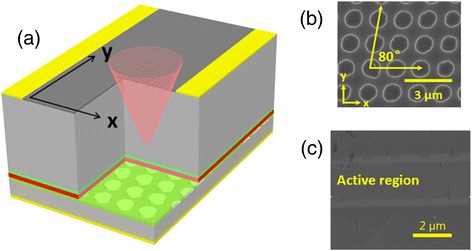
3D sketch, SEM, and cross section of the lattice. (a) Three-dimension (3D) sketch of a device. (b) Scanning electron microscope (SEM) image for centered rectangular photonic-crystal grating. (c) Cross section of the lattice after MOCVD regrowth.
2D photonic-crystal geometry obtains vertical coherent oscillation radiation over a broad area based on the band edge effect [21] with an increased optical path length, which leads to a gain enhancement. Typical square and hexagonal lattice have been principally investigated for years. As a novel structure, centered rectangular crystalline geometry attracted increasing attention [22,23] since it may have potential for a combination of advantages from square and hexagonal lattice. In order to make a comparison among the three types of PC structure and obtain optimized design parameters in our vertical emitting QCLs, we analyze the band structure and coupling coefficient of different types of 2D photonic-crystal.
By using bandsolve module of Rsoft, based on 2D plane wave (PW) expansion method [24], we first analyze the band structure for different types of lattice and calculate the number of band edge longitudinal modes simultaneously. Figure 2 shows the enlarged band structure near the Γ point of lattice PC with cross angle θ ranging from 90° to 60° in a step of 10°, and the insets at the bottom of each picture depict the pattern of different types of photonic-crystal. The number of band edge resonant fundamental longitudinal mode depends on the lattice structure. There are both four modes for square (Figure 2a) and centered rectangular lattice (Figure 2b,c) while six modes presented for hexagonal lattice (Figure 2d). It indicates that square and centered rectangular lattices are more likely to realize stable single longitudinal mode oscillation.
Figure 2.
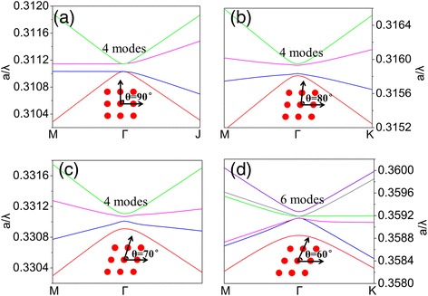
Band structure near the Γ point of lattice PC. With cross angle θ ranging from (a) 90°, square lattice. (b) 80° and (c) 70°, in turn, centered rectangular lattice. (d) 60°, hexagonal lattice.
We next investigate the impact of cross angle θ on the in-plane coupling coefficient. Given the chosen exposure period a0 and fixed radius of cylinder r, the coupling coefficients only change with the lattice cross angle θ. In the inset of Figure 3, the primitive translation vectors labeled , = a(−sin θ, cos θ) and the primitive reciprocal lattice vectors labeled , = mβ(−1, 0) where, ,
Figure 3.
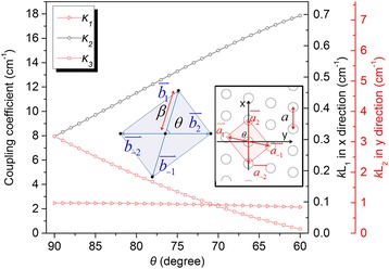
Coupling coefficients κ 1, κ 2, and κ 3 vs. lattice cross angle θ from 90° to 60°. The refractive index contrast Δn = 0.008. Inset: Right, centered rectangular lattice PC in real space with lattice constant a and lattice cross angle θ. Left, reciprocal lattice space corresponding to the real space with lattice constant β.
We calculate the coupling coefficients by using the following expression [25]:
| 1 |
| 2 |
| 3 |
For (l = m = 2) coupling order:
where A is the area of the primitive cell of the reciprocal lattice, refractive index contrast Δn = 0.008 derived from 1D effective index method [26], a0 = 1.49 μm, and r = 0.5 μm.
The coefficient κ1 accounts for distributed reflection-like diffraction into the counter propagating in-plane wave, such as from into or from into . The coefficient κ2 and κ3 represent diffraction into the oblique in-plane wave vectors into and into . Figure 3 shows the calculated coupling coefficient κ1, κ2, and κ3 as a function of lattice cross angle θ. We find that when θ changes from 90° to 60°, κ1 slightly reduces from 2.47 to 2.14 cm−1. Being different from κ1, the values of κ2 and κ3 are identical 7.96 cm−1 at the beginning; then, κ2 rapidly increases to 17.86 cm−1 and κ3 reduces to 0.35 cm−1. In order to obtain uniform modal intensity distribution throughout the device, the coupling strength κL, where L is the device length in the coupling direction, must be or close to 1 [27]. This means the centered rectangular lattice, especially for θ = 80°, enjoys an enlarged κ2L1 (L1 = 0.039 cm) = 0.45 and reduced κ3L2 (L2 = 0.4 cm) = 1.9 compared to square lattice that 0.3 and 3.2, respectively. Therefore, combining with the preceding analysis of the band structure, vertical emitting laser adopting centered rectangular lattice is a good compromise between square lattice and hexagonal lattice to achieve both single longitudinal mode operation and high efficiency vertical emitting.
Device fabrication
To make the buried CRPC grating, the top InP cladding was removed down to the upper InGaAs layer. A second-order CRPC lattice was defined on the upper InGaAs layer using DEHL technique and subsequently etched to a depth of 150 nm by wet chemical etching. The first exposure with a grating period of 1.49 μm was set along longitudinal direction, and the second exposure with the same period was oblique with a cross angle θ of 80°. The fabrication of our devices presented in this paper started from a CRPC lattice MOCVD regrowth ready QCL wafer. The sample was firstly processed into ridge mesa waveguide with a width of 390 μm. Then, the following processing procedures were similar to the description in ref. [11]. Finally, the wafer was cleaved into 4-mm-long bars with edge facet high reflective (HR) and substrate facet anti-reflective (AR) coating. For testing, the laser bars were mounted epilayer down on SiC submounts with indium solder, which were subsequently soldered on copper heat sinks.
Results and discussions
Device testing was done on an automatic temperature control stage. For electro-optical characterization, the substrate emitting output power was measured with a calibrated thermopile detector that collected laser radiation. The lasing spectra measurement was performed using a Fourier transform infrared spectrometer with a resolution of 0.125 cm−1 in rapid scan mode. 2D far-field was done by placing a mercury cadmium telluride (MCT) detector on a 2D stepped motor control translation stage (minimum step of 100 μm, maximum scans range of 4.5 × 4.5 cm), placed at 25 cm away from the laser. After collecting lock-in amplification of the detector signal from the far-field, we processed the data with distance coordinate into angle coordinate.
Our devices realized high-power operation above room temperature in pulsed mode with a pulse width of 400 ns and repetition frequency of 5 kHz. Figure 4 shows the power versus current (L-I) characterization of a 4-mm-long CRPC substrate emitting QCL with ridge width of 390 μm at different heat sink temperatures. At 10°C, the laser emits up to maximum peak power of 10.3 W with slope efficiencies around 0.38 W/A and threshold current density around 1.86 kA/cm2. The maximum wall plug efficiency (WPE) of 1.1% was obtained at a current of 60 A. When the temperature rises up to 50°C, the corresponding value drops to 7.7 W, 0.29 W/A and increases to 2.15 kA/cm2. The inset of Figure 4 shows the semilog plot of single-mode emission spectra at an injection current of 1.1Ith between 15°C and 65°C with a step of 5°C. Single longitudinal mode emission with a side mode suppression ratio (SMSR) of about 30 dB at the entire temperature range is obtained. The peak emission spectrum is observed to shift from 2,112.4 cm−1 at 15°C to 2,104.6 cm−1 at 65°C, corresponding to a temperature tuning coefficient ∇v/∇T = −0.155 cm−1 C−1.
Figure 4.
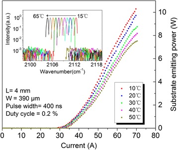
Power versus current (L-I) characterization of a 4-mm-long CRPC substrate emitting QCL. With a ridge width of 390 μm at different heat sink temperatures between 10°C and 50°C. The inset shows the semilog plot of single-mode emission spectra at an injection current of 1.1Ith under pulsed mode operation, and a SMSR of 30 dB is maintained for the entire temperature range of 15°C to 65°C. Device edge facets were high-reflective coated, and substrate facets were anti-reflective coated.
Providing that the fundamental transverse mode (TM00) has priority to lase, vertical emitting devices with PC grating are capable of providing large scale of emitting apertures. So substrate emitting CRPC quantum cascade lasers will emit more light energy propagating along highly compressed spatial paths. Figure 5 shows the measured far-field intensity distributions for the substrate emitting device. The definition of the angular coordinates θx and θy in the far-field are corresponding to x- and y-axis in Figure 1a. At low injection current of 33.0 A (Figure 5a), a small divergence far-field was obtained and the full width at half maximum (FWHM) of the main lobe emission cone is θx × θy = 0.65° × 0.31°. At higher current levels (Figure 5b), an increased broadening of the main lobe (1.1° × 0.45°) is observed due to more pronounced thermal effects especially for broad area laser related to self-focusing effect [28]. Figure 5c shows the 1D far-field in θx direction derived from Figure 5a. The small dotted lines labeled TM00, TM03, and TM06 correspond to 1D fitting of the different order transverse far-field distribution. TM03 and TM06 is the third- and sixth-order transverse mode, respectively. In this direction, the far-fields exhibits hybrid transverse mode. Based on the measured 2D far-field intensity distributions (Figure 5a,b), we calculate the proportion of each transverse mode. At 33.0 A, TM00 weights with 35.7%, TM03 34.7%, and TM06 29.6%. At 53.3A, TM00 increased to 39.1%, TM03 down to 32.7%, and TM06 28.2%. In addition, we find that the whole electric field intensity distribution in θx direction is slightly tilted by connecting a line of shoulder peak and main peak because the wave vector of is oblique with by an angle of 80°. The emergence of TM03 and TM06 indicates that their losses are insufficient to suppress the gain. Figure 5d shows the 1D far-field in θy direction derived from Figure 5a. The measurement far-field divergence angle in θy is much larger than diffraction-limited spreading angle 0.08°, which is mainly due to the real divergence angle which is too small for our measurement system to distinguish.
Figure 5.
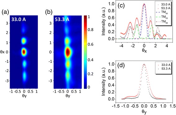
Measured far-field intensity distributions for the substrate emitting device. (a) 2D far-field intensity distribution under pulsed driving current of 33.0 A. (b) 53.3 A. (c) Measured 1D far-fields for θx correspond to (a) and (b) for comparison. Simulated results of TM00, TM03, and TM06 are depicted using dotted lines (d) 1D far-fields for θy.
Mode competition in longitudinal and transverse direction strongly depends on driving the current [29]. In the far-field testing, we find an interesting phenomenon that the +2, +1, 0, −1, and −2 order beam peak intensities in θx direction are changing in a certain manner as the injection current increases, where the 0 order position correspond to TM00, and (+1,−1) pair corresponds to TM03 and (+2,−2) TM06. As shown in Figure 6, the 0 order and other high-order peak intensity increases as the driving current comes up to near 48 A. Then, the intensity of 0 order quickly rises to the maximum value as the driving current comes up to near 51.0 A. In contrast, +1 and −1 orders fall down to a low value while +2 and −2 orders jump up to a high value directly at the moment. This qualitatively reveals a transverse mode competition that TM03 is suppressed. Subsequently when the current continues to increase beyond 51.0 A, the TM00 begins to be weakened and the transverse far-field in θx direction exhibits a strong tendency towards higher mode distribution.
Figure 6.
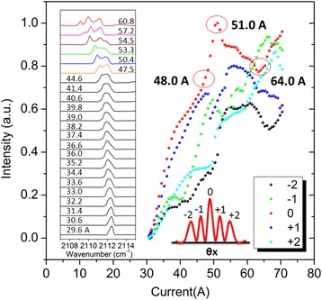
Intensity for +2, +1, 0, −1, and −2 order beam peaks under various injection current. From 1.05Ith to 2.1Ith at room temperature. Inset: Spectra of the CRPC substrate emitting QCL under an increased injection current from 29.6 to 60.8 A.
The left inset of Figure 6 shows the lasing spectra under pulsed operation at different current from 1.05Ith to 2.1Ith. The tested laser shows single longitudinal mode operation at low injection current level. When the injection current increases, the FWHM of spectrum widens from 0.44 cm−1 (29.6 A) to 1.16 cm−1 (44.6 A), and even muti-wavelength lasing (>46.0 A). This may be due to the nonuniform refractive index of 2D photonic-crystal DFB grating, resulting from inherent linear Gaussian-like distribution of heat in the active region, giving rise to a longitudinal inhomogeneous gain profile of different spectrum. It is much more obvious for a broad area device to suffer spectrum widening since the operation current is so high that more electric energy transform into heat. In the future, when a shorter pulsed width source is applied for the drive of QCL, the single longitudinal mode emission may persist to a higher operating current.
Conclusions
In conclusion, we report a high power and small divergence substrate emitting centered rectangular photonic-crystal quantum cascade laser. A record maximum peak output power for vertical emitting QCLs exceeding 10 W is obtained. Divergence far-field angle below 1° (0.65° × 0.31°) for QCLs is first realized. And the main lobe of far-field occupies approximately 40% of output energy. The laser shows a strong single longitudinal mode operation around 4.73 μm with SMSR of 30 dB even at high temperature.
Acknowledgements
This work was supported by the National Basic Research Program of China (Grant Nos. 2013CB632801, 2013CB632803), National Natural Science Foundation of China (Grant No. 61435014, 61306058, 61274094), and Beijing Natural Science Foundation (Grant No. 4144086).
We thank P. Liang and Y. Hu for their contributions in the device fabrication.
Abbreviations
- AR
anti-reflective
- CRPC
centered rectangular photonic-crystal
- CW
continuous wave
- DEHL
double-exposure holographic lithography
- DFB
distributed feedback
- HR
high reflectivity
- MCT
mercury cadmium telluride
- PC
photonic-crystal
- QCLs
quantum cascade lasers
- SEM
scanning electron microscope
- SE-QCLs
substrate emitting quantum cascade lasers
- TM00
fundamental transverse mode
Footnotes
Competing interests
The authors declare that they have no competing interests.
Authors’ contributions
DYY designed the waveguide structure, fabricated the device, performed the testing, and wrote the paper. JCZ and FQL provided the concept, wrote the paper, and supervised the project. OC revised the paper. SQZ and YHL performed the testing. ZWJ completed the MOCVD regrowth process. ZGW supervised the project. All authors read and approved the final manuscript.
Contributor Information
Dan-Yang Yao, Email: dyyao@semi.ac.cn.
Jin-Chuan Zhang, Email: zhangjinchuan@semi.ac.cn.
Olivier Cathabard, Email: olivier@semi.ac.cn.
Shen-Qiang Zhai, Email: zsqlzsmbj@semi.ac.cn.
Ying-Hui Liu, Email: yhliu@semi.ac.cn.
Zhi-Wei Jia, Email: jiazw@semi.ac.cn.
Feng-Qi Liu, Email: fqliu@red.semi.ac.cn.
Zhan-Guo Wang, Email: zgwang@semi.ac.cn.
References
- 1.Mujagic E, Hoffmann L, Schartner S, Nobile M, Schrenk W, Semtsiv M, et al. Low divergence single-mode surface emitting quantum cascade ring lasers. Appl Phys Lett. 2008;93:161101. doi: 10.1063/1.3000630. [DOI] [Google Scholar]
- 2.Xu G, Chassagneux Y, Colombelli R, Beaudoin G, Sagnes I. Polarized single-lobed surface emission in mid-infrared, photonic-crystal, quantum-cascade lasers. Opt Lett. 2010;35:859. doi: 10.1364/OL.35.000859. [DOI] [PubMed] [Google Scholar]
- 3.Chen JY, Liu JQ, Guo WH, Wang T, Zhang JC, Li L, et al. High-power surface-emitting surface-plasmon-enhanced distributed feedback quantum cascade lasers. IEEE Photonic Tech L. 2012;24:972. doi: 10.1109/LPT.2012.2192724. [DOI] [Google Scholar]
- 4.Sigler C, Kirch JD, Earles T, Mawst LJ, Yu Z, Botez D. Design for high-power, single-lobe, grating-surface-emitting quantum cascade lasers enabled by plasmon-enhanced absorption of antisymmetric modes. Appl Phys Lett. 2014;104:131108. doi: 10.1063/1.4869561. [DOI] [Google Scholar]
- 5.Mickelson AR, Basavanhally NR, Lee YC. Optoelectronic packaging. New York: Wiley–Interscience; 1997. [Google Scholar]
- 6.Zhang QD, Liu FQ, Zhang W, Lu QY, Wang LJ, Li L, et al. Thermal induced facet destructive feature of quantum cascade lasers. Appl Phys Lett. 2010;96:141113. doi: 10.1063/1.3374335. [DOI] [Google Scholar]
- 7.Hofstetter D, Faist J, Beck M, Oesterle U. Surface-emitting 10.1 μm quantum-cascade distributed feedback lasers. Appl Phys Lett. 1999;75:3769. doi: 10.1063/1.125450. [DOI] [Google Scholar]
- 8.Schrenk W, Finger N, Gianordoli S, Hvozdara L, Strasser G, Gornik E. Surface-emitting distributed feedback quantum-cascade lasers. Appl Phys Lett. 2000;77:2086. doi: 10.1063/1.1313807. [DOI] [Google Scholar]
- 9.Pflugl C, Austerer M, Schrenk W, Golka S, Strasser G, Green R, et al. Single-mode surface-emitting quantum-cascade lasers. Appl Phys Lett. 2005;86:211102. doi: 10.1063/1.1929070. [DOI] [Google Scholar]
- 10.Lyakh A, Zory P, DSouza M, Botez D, Bour D. Substrate-emitting, distributed feedback quantum cascade lasers. Appl Phys Lett. 2007;91:181113. doi: 10.1063/1.2803851. [DOI] [Google Scholar]
- 11.Yao DY, Zhang JC, Liu FQ, Zhuo N, Yan FL, Wang LJ, et al. Surface emitting quantum cascade lasers operating in continuous-wave mode above 70°C at λ ∼ 4.6 μm. Appl Phys Lett. 2013;103:041121. doi: 10.1063/1.4816722. [DOI] [Google Scholar]
- 12.Zhang JC, Yao DY, Zhuo N, Yan FL, Liu FQ, Wang LJ, et al. Directional collimation of substrate emitting quantum cascade laser by nanopores arrays. Appl Phys Lett. 2014;104:052109. doi: 10.1063/1.4864633. [DOI] [Google Scholar]
- 13.Bai Y, Tsao S, Bandyopadhyay N, Slivken S, Lu QY, Caffey D, et al. High power, continuous wave, quantum cascade ring laser. Appl Phys Lett. 2011;99:261104. doi: 10.1063/1.3672049. [DOI] [Google Scholar]
- 14.Bai Y, Slivken S, Darvish SR, Haddadi A, Gokden B, Razeghi M. High power broad area quantum cascade lasers. Appl Phys Lett. 2009;95:221104. doi: 10.1063/1.3270043. [DOI] [Google Scholar]
- 15.Yao DY, Zhang JC, Liu FQ, Jia ZW, Yan FL, Wang LJ, et al. 1.8-W room temperature pulsed operation of substrate-emitting quantum cascade lasers. IEEE Photonic Tech L. 2014;26:323. doi: 10.1109/LPT.2013.2293495. [DOI] [Google Scholar]
- 16.Meier M, Mekis A, Dodabalapur A, Timko A, Slusher RE, Joannopoulos JD, et al. Laser action from two-dimensional distributed feedback in photonic crystals. Appl Phys Lett. 1999;74:7. doi: 10.1063/1.123116. [DOI] [Google Scholar]
- 17.Imada M, Noda S, Chutinan A, Tokuda T, Murata M, Sasaki G. Coherent two-dimensional lasing action in surface-emitting laser with triangular-lattice photonic crystal structure. Appl Phys Lett. 1999;75:316. doi: 10.1063/1.124361. [DOI] [Google Scholar]
- 18.Vurgaftman I, Meyer JR. Photonic-crystal distributed-feedback quantum cascade lasers. IEEE J Quantum Electron. 2002;38:592. doi: 10.1109/JQE.2002.1005409. [DOI] [Google Scholar]
- 19.Zhang JC, Liu FQ, Tan S, Yao DY, Wang LJ, Li L, et al. High-performance uncooled distributed-feedback quantum cascade laser without lateral regrowth. Appl Phys Lett. 2012;100:112104. doi: 10.1063/1.3693410. [DOI] [Google Scholar]
- 20.Lu QY, Guo WH, Zhang W, Wang LJ, Liu JQ, Li L, et al. Room temperature operation of photonic-crystal distributed-feedback quantum cascade lasers with single longitudinal and lateral mode performance. Appl Phys Lett. 2010;96:051112. doi: 10.1063/1.3295704. [DOI] [Google Scholar]
- 21.Dowling JP, Scalora M, Bloemer MJ, Bowden CM. The photonic band edge laser: a new approach to gain enhancement. J Appl Phys. 1994;75:1896. doi: 10.1063/1.356336. [DOI] [Google Scholar]
- 22.Peng C, Liang Y, Sakai K, Iwahashi S, Noda S. Three-dimensional coupled-wave theory analysis of a centered-rectangular lattice photonic crystal laser with a transverse-electric-like mode. Phys Rev B. 2012;86:035108. doi: 10.1103/PhysRevB.86.035108. [DOI] [Google Scholar]
- 23.Iwahashi S, Sakai K, Kurosaka Y, Noda S. Centered-rectangular lattice photonic-crystal surface-emitting lasers. Phys Rev B. 2012;85:035304. doi: 10.1103/PhysRevB.85.035304. [DOI] [Google Scholar]
- 24.Plihal M, Shambrook A, Maradudin AA, Sheng P. Two-dimensional photonic band structures. Opt Commun. 1991;80:199. doi: 10.1016/0030-4018(91)90250-H. [DOI] [Google Scholar]
- 25.Vurgaftman I, Meyer JR. Photonic-crystal distributed-feedback lasers. Appl Phys Lett. 2001;78:1475. doi: 10.1063/1.1355670. [DOI] [Google Scholar]
- 26.Bai Y, Darvish SR, Slivken S, Sung P, Nguyen J, Evans A, et al. Electrically pumped photonic crystal distributed feedback quantum cascade lasers. Appl Phys Lett. 2007;91:141123. doi: 10.1063/1.2798062. [DOI] [Google Scholar]
- 27.Kogelnik H, Shank CV. Coupled-wave theory of distributed feedback lasers. J Appl Phys. 1972;43:2327. doi: 10.1063/1.1661499. [DOI] [Google Scholar]
- 28.Fibich G, Gaeta AL. Critical power for self-focusing in bulk media and in hollow waveguides. Opt Lett. 2000;25:335. doi: 10.1364/OL.25.000335. [DOI] [PubMed] [Google Scholar]
- 29.Fuchs F, Kirn B, Mann C, Yang Q, Bronner W, Raynor B, et al. Spectral tuning and mode competition of quantum cascade lasers studied by time-resolved Fourier transform spectroscopy. Proc of SPIE. 2006;6386:63860I–9. doi: 10.1117/12.685379. [DOI] [Google Scholar]


