

Abstract
The recent proliferation of three dimensional (3D) printing technologies has allowed the exploration of increasing complex designs, and, furthermore, the consideration of 3D printed constructs for biological applications. However, there is an unmet need for a consistent set of tools for the design and evaluation of these biological 3D printed constructs, particularly as they relate to engineered tissues. For example, identifying the most advantageous construct parameters for the rapid vascularization of an engineered tissue - a critical parameter in regenerative medicine - is difficult without a common group of measures. We demonstrate here a toolbox to design, characterize, and evaluate 3D printed scaffolds for vascularized tissue regenerative medicine. Our toolbox (1) identifies the range of design specifications using a modular design, (2) nondestructively compares the 3D printed scaffolds to the design, (3) evaluates biocompatibility and mechanical properties, and (4) predicts host vessel integration. As a case study, we designed, fabricated, and evaluated polymer scaffolds using a poly(propylene fumarate) based resin. Our work highlights the potential for these tools to be combined as a consistent methodology for the evaluation of porous 3D printed constructs for regenerative medicine.
Keywords: 3D printing, scaffolds, tissue engineering, vascularization
Narrative
The development and use of three dimensional (3D) printed scaffolds represents a huge opportunity for the regenerative medicine community. However, once a design is created and fabricated, evaluation of what is a successful design for host integration remains a non-standardized process. There is an unmet need for a consistent set of tools to evaluate 3D printed regenerative medicine designs. This study proposes a combined set of methods, or a toolbox, that can be used to identify scaffold designs for enhanced host integration into vascularized musculoskeletal tissues. Our toolbox consists of the following techniques: (1) modular design, (2) micro computed tomography evaluation, (3) biocompatibility and mechanical testing, and (4) in silico modeling. These methods evaluate scaffolds by first identifying the range of possible designs available for the scaffolds using a modular approach. Then a set of scaffold parameters from within the design space is chosen for fabrication and the 3D printed scaffolds are nondestructively compared to the design specifications. The scaffolds are evaluated for biocompatibility and mechanical attributes, according to well established International Organization for Standardization (ISO) and American Society for Testing and Materials International (ASTM) standards. Lastly, they are evaluated for successful host integration by modeling angiogenesis. This approach can be applied to the broad scope of tissue engineered products, from conception through development. We illustrate this methodology by applying our toolbox to the design and evaluation of porous 3D printed poly(propylene fumarate) (PPF) scaffolds. The results of the PPF case study were compared to an in vivo model. We note that previous investigations have utilized this well established subcutaneous in vivo model to evaluate vascular ingrowth and biocompatibility.[1–4]
3D printing represents an accurate (i.e., matches design) and precise (i.e., reproducible) method for the fabrication of porous scaffolds; however, we would like to establish a method for evaluating printed materials for biological applications, and particularly tissue engineering. Currently, the most common methods for evaluating parameters of a tissue engineered scaffold, such as porosity and pore size, are destructive.[5] Therefore, we sought to implement a nondestructive method to evaluate the fabricated scaffold. This method can be used after the initial printing of the scaffold and throughout its lifetime. Evaluation over the scaffold’s lifetime - from implantation through complete reabsorption after degradation - allows for the researcher to understand the impacts of small changes in pore size which may impact cell and tissue ingrowth.[6–9] These small changes in scaffold properties after implantation may also provide clues as to changes in mechanical properties.
Suitable mechanical properties and biocompatibility are necessary characteristics for a successful tissue engineering scaffold. The critical role of the mechanical properties of a scaffold is well understood as they are required to resist fracture under native physiological load and is a requirement of many implanted materials. Similarly, guidelines for biocompatibility have been well established to ensure successful native tissue interaction after the material implanted. As biocompatibility and specific mechanical properties are commonly required for many implanted materials, there has been significant research into developing consistent evaluation methods.[10, 11] For this study, we used PPF as the main polymer resin component to print the scaffold designs. PPF has been thoroughly characterized for its mechanical and biocompatibility properties.[12–16] Additionally, PPF is biodegradable and photocrosslinkable that has been has shown to exhibit minimal cytotoxicity.[16–20] Since the biocompatibility and mechanical properties have been well established for PPF, we will discuss the other methods that comprise our toolbox to identify the necessary scaffold parameters for successful vessel ingrowth.
In addition to mechanical stability, successful regenerative medicine scaffolds provide architecture conducive to cell attachment, vascularization, and tissue ingrowth.[21] One of the most important factors of successful host integration is the development of a vascular network within the scaffold after implantation.[22] Development of a vascular network has been shown to be successful with porous, degradable scaffold sleeve designs with a lumen.[23] Such a design, like our scaffold design (Figure 1), can provide the required mechanical support, while also allowing for proper nutrient and waste transport and vascularization. Specifically, this design allows the outer shell to withstand compressive loads within a load bearing defect when fabricated using a high modulus material like PPF, as well as allows the interior lumen to deliver a biologically active component, such as bone marrow or cells encapsulated within a fragile hydrogel. Finally, the hollow, cylindrical design is also porous to allow for improved nutrient transport and vessel ingrowth compared to solid wall designs.
Figure 1. Design of Standardized Modular Scaffolds.

(a) Repeating Unit of Modular Scaffold Design. Base and post ring structure that is used as the repeating unit to create the scaffold designs. The modular design can be tuned by varying post number, base height and wall thickness to create a range of pore sizes and porosities. (b – e) Sample Scaffolds with 100 μm Wall Thickness. (b) 400 μm pore size, 50 % porosity, (c) 800 μm pore size, 25 % porosity, (d) 400 μm pore size, 25 % porosity, and (e) 800 μm pore size, 50 % porosity. (f – i) Sample Scaffolds with 500 μm Wall Thickness. (f) 400 μm pore size, 25 % porosity, (g) 800 μm pore size, 25 % porosity, (h) 400 μm pore size, 50 % porosity, and (i) 800 μm pore size, 50 % porosity. (j) Effect of Post Height on Porosity. Increasing post height allows for a greater range of porosity. Smaller wall thickness (blue) modular designs allow for a greater range of porosities. (k) Effect of Post Height and Number of Posts on Porosity. As the number of posts increase, the range of possible porosities decreases.
Research suggests that an ideal approach for obtaining precise mechanical and nutrient transport properties is through the use of modular scaffold designs.[24] Modular scaffold designs consist of a repeating unit that may be individually modified and then combined to create a complete scaffold. Modular designs allow for tuning of the scaffold parameters such as pore size and porosity. Tuning porosity and pore size may be used to control degradation rate and mechanical properties which in turn may be optimized for cell differentiation and neotissue formation.[5] In bone tissue engineering applications, the use of a modular design may allow for the optimization of porosity, while constraining other properties such as elastic strength. Previously, varying pore sizes and porosities within an individual modular design was difficult to achieve when using “random” scaffold fabrication methods, such as porogen leaching. This, in turn, made it difficult to decouple the effects of pore properties and mechanical properties. 3D printing has facilitated the fabrication of complex designs at very high resolution, with accuracies of 15 to 60 μm, creating layers 60 μm thick.[25] Modeling the wide range of scaffold parameters available with modular designs allows us to identify the design space in which we can choose the optimal scaffold parameters to best elicit the desire physiological response.
The variables of porous designs, such as the pore size and porosity, of cell-seeded scaffolds are well known as key parameters determining successful tissue engineered constructs.[26] In examining bone as an example, we want to promote bone formation and vessel ingrowth, and these outcomes are greatly influenced by cell attachment, cell distribution, and cell migration, which in turn affect the cell signaling for osteogenic differentiation.[6] Additionally, pore size and porosity have been shown to impact vascularization and osteoconduction.[7–9, 15] For example, scaffolds with pore sizes of 2 to 6 μm and 33.5 % porosity yielded no bone ingrowth, while scaffolds with 30 to 100 μm pore sizes and 46.9 % porosity yielded 50 μm of osteoid and fibrous tissue ingrowth.[27, 28] Factors such as degradation rate and mechanical stability are highly dependent on pore size and porosity, ultimately affecting bone formation.[6] Similarly, scaffolds with pores greater than 140 μm demonstrated increased functional capillary density compared to scaffolds with smaller pores.[29] Other studies suggest that the rate of vascularization increases with increasing pore sizes, and at a pore size of 270 μm the potential for scaffold interference in vascularization is removed.[2] Interconnected pores ranging from 300 to 500 μm are known to improve nutrient flow.[23] For some scaffold fabrication techniques, rendering sufficiently accurate pores to obtain specific porosities is difficult, requiring a new approach, such as 3D printing.[26] 3D printing allows for the fabrication of complicated designs with high precision and accuracy. For such designs, a variety of combinations of pore size and porosity can be obtained, allowing for tailoring of degradation rate, mechanical strength, and interconnectivity of the construct. After selecting a set of scaffold designs that are composed of biocompatible materials and have the physiologically appropriate mechanical properties the next step is to evaluate which design optimizes vascularization.
Current methods to measure vascularization use animal models as the gold standard. In vivo studies are integral to evaluating the biological response; however, ideally, an in vivo study would be implemented at the last stage of development. Identifying the optimal combination of parameters for vascularization earlier in the design process would accelerate the process by reducing the number of designs investigated with each step in the toolbox. Moreover, refinement of the scaffold design prior to the in vivo stage is beneficial for implementing the 3Rs of replacement, reduction, and refinement of animal models.[30] Therefore to evaluate vessel ingrowth we suggest the use of an in silico model as an integral component of our toolbox. The in silico model we recommend has accurately replicated angiogenesis.[2] This in silico model allows for the investigation of a wide range of combined scaffold parameters that would be difficult and time consuming recreate the wide range of designs physically. Now that we have identified the steps in our toolbox necessary to examine the wide range of scaffold parameters, we applied our methodology to a case study of porous PPF scaffolds.
To utilize this set of tools, we designed, fabricated, characterized, and evaluated porous PPF scaffolds consisting of modular ring-shaped bases. The first step was to use modular design to identify the wide range of scaffold designs that are feasible with defined pore sizes, base heights, and number of posts. For example, modification of the number of posts may be used to change the size of the pores. Of the wide range of variables identified within the range of possible designs, twelve scaffold designs were selected with varying porosities, pore sizes, and wall thicknesses. Eight of the twelve theoretical designs are pictured in Figure 1b – 1i with wall thicknesses of 100 μm (Figure 1b – 1e) and 500 μm (Figure 1f – 1i). The designs include three different porosities (25%, 38%, and 50%), and two pore sizes (400 μm and 800 μm). Figure 1j shows that porosity increases with increasing the height of the posts connecting the modular ring structures. Conversely, modeling the effect of base height on porosities showed that increasing the base height to 500 μm (red), from 100 μm (blue), results in a smaller range of porosities (Figure 1j). Figure 1k highlights the trend that as the number of posts increases, the range of possible porosities decreases. Conversely, as post height increases, the range of possible porosities increases. A large range of possible porosities and pore sizes is necessary for the wide range of native tissues that regenerative medicine addresses. Of the twelve designs within the range of design specifications, four were chosen for the next steps in the toolbox to provide a broad range of tissue engineering scaffold properties (pore size, porosity, and wall thickness).
Four of the twelve designs were fabricated using an EnvisionTEC Perfactory® 3 from a PPF-based polymer resin. This absorbable polymer has been optimized in previous work for 3D printing with high levels of precision.[31] To evaluate the precision and accuracy of the 3D fabricated designs, micro computed tomography (μCT) was implemented as the second step in our toolbox. μCT was initially used to nondestructively image the fabricated scaffolds (Figure 2a – 2d), and this data set was compared to the design specifications. For each design, the intended pore size, porosity, and wall thickness were compared to their corresponding physical construct parameter (Figure 2e). Similar values to the design specification for the porosity were achieved for three of the four scaffolds (Figure 2a – 2c); however, pore sizes were smaller than the designed values. Successful fabrication was deemed at greater than 70% conformity to the CAD model, owing to the intended application and the scale at which pore size is thought to impact vascularization. The scaffolds with larger pores, Figures 2a and 2b, achieved this goal; however, the scaffolds with smaller pores, Figures 2c and 2d, did not. For the scaffold designs with 400 μm pores, the printed scaffolds had an average pore size 63% and 70% of the intended pore sizes. The scaffold design with 38% porosity, 400 μm pores, and 500 μm wall thickness (Figure 2d) exhibited the largest deviation from the design, with the porosity at 53%, pore size at 70%, and wall thickness at 78% of the design specifications (Figure 2e). Conversely, the two scaffolds that were most accurately fabricated had 800 μm pores; with porosities that were 88% and 90%, pore sizes at 80% and 70%, and wall thicknesses of 91% and 79% of the design specifications. In comparison with porogen leached scaffold fabrication, which creates pores based on the size of the porogen, the 3D printed pores were printed with a tighter tolerance allowing for greater control of the scaffold parameters.[32, 33] The μCT 3D renderings and quantification of the printed scaffold parameters show promise for the fabrication of complex designs. The greatest design conformance was seen with the wall thickness and the overall porosity; however, the pore size was consistently found to the smaller than the design specification.
Figure 2. μCT Characterization of 3D Printed Scaffolds.

(a – d) μCT 3D Renderings of Scaffolds. (a) 800 μm pores, 25% porosity, (b) 800 μm pores, 50% porosity, (c) 400 μm pores. 25% porosity, (d) 800 μm pores, 38% porosity. (e) Comparison of 3D Printed Scaffolds with Scaffold Design Parameters. Nondestructive analysis of scaffold pore size, porosity and wall thickness was performed using Image Processing Language. Scaffold parameters are compared to designed parameters. Printing accuracy was measured by calculating the percent difference between the built scaffold parameters compared to the scaffold design parameters. 3D printing was most accurate for 500 μm wall thickness scaffolds, with 91% accuracy for the 800 μm and 25% porosity scaffold design. (n = 4)
Overall, the combination of the Perfactory® device and the PPF resin were able to fulfill the desired ranges of porosities and wall thicknesses; however, the pore sizes ranged from 63% to 80% of the designed values (Figure 2). The undesired infilling of designed pore spaces and subsequent rounding of the pores is thought to be due to extraneous photocrosslinking caused by the light scattering effects of the resin and post-curing shrinkage of the polymer.[31] The rounding of the edges is best seen in the scaffold with 38% porosity and 400 μm pore size (Figure 2d). This unintentional curing is referred to as “dark cure” or “over cure”.[31] Dark cure is polymerization of polymer due to scattered light in locations where light has not been projected, i.e., the areas designed to be dark and uncured. Additionally, high viscosity polymer resins, like PPF, have been shown to negatively impact printing resolution with the undesired filling of pore spaces.[25] Over cure is observed with the crosslinking of the polymer resin beyond the dimensions in the design specification that are perpendicular to the build plate. This highlights some areas of future research for improving the accuracy and reproducibility of 3D printing. Now with the understanding of the dimensions of the fabricated scaffolds, we were interested in the potential of angiogenesis of these different designs, or the last step in the toolbox.
We evaluated the potential for vessel ingrowth into the scaffolds using a 3D agent-based model of angiogenesis.[34] This in silico model was used to investigate the effect of pore size, porosity, and wall thickness on the rate and depth of vascularization of the scaffolds through models consisting of a quarter of the circumference of the scaffold. Variations in pore size, porosity, and wall thickness exhibited were found to alter vascularization (Figure 3). Scaffolds with 200 μm, 400 μm, and 800 μm pore sizes, 25% and 50% porosities, and 100 μm and 500 μm wall thicknesses were evaluated for their vascularization potential following implantation in vivo. Angiogenesis was assessed using six metrics, based on previous literature, as described in the methods below (Figure 3a).[34] All angiogenesis metrics were found to increase with porosity when other properties (wall thickness, pore size) were held constant.
Figure 3. In Silico and In Vivo Angiogenesis Analysis.
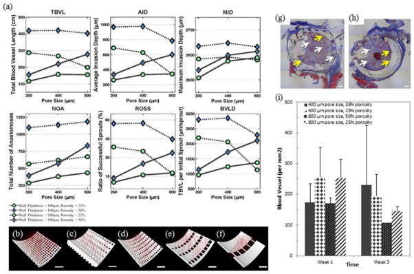
(a – f) Results of In Silico Angiogenesis. (a) In silico angiogenesis of twelve different scaffold designs with two different wall thicknesses and three different pore sizes was evaluated for six different parameters: total blood vessel length (TBVL), average invasion depth (AID), maximum invasion depth (MID), total number of anastomoses (NOA), ratio of successful sprouts (ROSS), and TBVL per initial sprout (TBVLS). A smaller wall thickness (100 μm) was found to promote most measures of angiogenesis. However, at the smaller wall thickness, increasing pore size had no impact on ROSS, TBVL, or AID. Scaffolds with high porosity (50%), wall thickness of 100 μm, and small/medium pore sizes (200 – 400 μm) had the best values for all six vascularization metrics. (b – f) Images of in silico vascularization at 3 weeks. (b – c) Thinner walled scaffolds resulted in greater vascularization, as seen by greater number and length of vessels, correlating with all six parameters. Scaffolds shown have 200 μm pore size, 50% porosity, and (b) 100 μm and (c) 500 μm wall thickness. (d – f) As pore size increases, vascularization decreases while porosity is held constant. Scaffolds shown have 25% porosity, 100 μm wall thickness and (d) 200 μm, (e) 400 μm and (f) 800 μm pore size. Scale bar represents 100 μm. (g – i) In Vivo Angiogenesis. (g – h) Massons trichrome staining showing tissue formation within 500 μm wall thickness scaffolds with (g) 400 μm pore size, 38% porosity and (h) 800 μm pore size, 25 % porosity. Blood vessels and collagen can be seen between the scaffold posts and within the core of the scaffold. White arrows point to blood vessels. Yellow arrows point to a modest inflammatory cell response at the interface with the PPF. Blue staining is collagen and shows an overall standard fibrovascular response with collagen formation. Scale bar represents 500 μm. (i) Vessel density in the tissue growing within the pores of the scaffolds determined from immunohistochemical stains for CD31. There are no statistical differences in vessel density within the pores for these conditions (n = 2).
We also observed in silico that vascularization decreased with increasing wall thickness. This is clearly seen when comparing the growth of vessels in scaffolds with 100 μm wall thickness in comparison to 500 μm (Figure 3b – 3c). A greater density and depth of vessels is observed in scaffolds with thinner walls. Interestingly, with 100 μm wall thickness, vascular parameters, such as maximum invasion depth (MID), ratio of successful sprouts (ROSS), depth of invasion (AID), and total blood vessel length (TBVL), generally decrease with increasing pore size when porosity remains constant. This is highlighted in Figures 3d – 3f, where the thickness of the scaffold base increases as the pore size is increased to maintain a constant porosity.
One interesting finding is that as pore size increases to 800 μm, wall thickness has less of a detrimental impact on vascularization. This is highlighted in the 800 μm pore size cases, where MID, ROSS, and total blood vessel length per initial sprout (TBVLS) metrics are seen to have similar results for the same size porosity. For the scaffolds with 25% porosity and 800 μm pores, the MID for the thicker wall (500 μm) is slightly larger than the same scaffold with a thinner wall (100 μm). Similarly for the 50% porosity, 800 μm scaffolds, MID increased modestly when the scaffold wall thickness decreased from 500 to 100 μm. The effect of very small pore sizes is similar to the effect of wall thickness. In both cases, large surfaces exist in the scaffold that hinder sprout invasion. As a result, when wall thickness is high, increasing the pore size improves the results. However, when wall thickness is low, increasing the pore size has either no effect or a modest negative effect on the ROSS, TBVL and AID (Figure 3). As expected, in all cases in this study, increasing porosity has a positive effect on depth and rate of scaffold vascularization. By controlling these scaffold parameters one can influence as well as improve nutrient and waste transport to and from the defect site. In general, agent-based predictions based on the smaller wall thickness of 100 μm showed increased angiogenesis compared to wall thickness of 500 μm (Figure 3). The optimal scaffold designs for vascularization were found to have high overall scaffold porosity (50 %), low thickness (100 μm), and small or medium pore sizes (200 – 400 μm). Along with wall thickness, porosity was shown to play an important role with all six measures of angiogenesis that increase with increasing porosity. These results may be altered by a different surface geometry: our hollow design facilitates vascular ingrowth into the core, whereas vascular development in a solid scaffold with interconnected pores is likely to be heavily dependent upon the porous architecture. Finally, we must note that the in silico model does not specifically consider the effects of inflammation, and as inflammation is well know to impact vascularization, this is an inherent limitation of the model.
Vascularization of the scaffold designs was further investigated in vivo by implanting four scaffold designs in a subcutaneous implant model (Figure 3g – 3i). At harvest, the explanted scaffolds appeared intact and were surrounded by a layer of fibrovascular tissue. Histologically, tissue invasion was observed within the scaffold for all conditions. The tissue exhibited a typical inflammatory response with a large density of vessels and significant collagen production. No signs of chronic inflammation, encapsulation, or multinucleated foreign body giant cells were observed. Vessels could be seen growing within the pores of the scaffolds (Figure 3g and 3h). Vessel density was analyzed using CD31 immunostains, and similar levels of vessel density were observed in all four scaffolds designs. Similar to the computational predictions, vascular networks were observed growing in the pores in all scaffold conditions. Quantitative analysis of vascular density did not show any differences between conditions (Figure 3i) as suggested by the in silico model. However, we note that the model predicted that wall thickness had the largest effect upon vascularization, and samples with the same wall thickness presented only modest differences in the various measures of vascularization. In addition, the computational model presents an evaluation of the 3D structure that cannot be determined from the essentially two dimensional (2D) tissues sections. Regardless, the results show that the scaffolds enable vascularized tissue ingrowth into the core as suggested by our methods in the toolbox. We suggest that to refine the toolbox, and better match physiological outcomes, a model of the fabricated scaffold could be evaluated in silico. Therefore the scaffolds’ actual pore size, porosity, and wall thickness would be used within the model. Furthermore, the in silico data could be compared with in vivo results using μCT to better image three dimensionally the vessel penetration of the scaffolds compared to the 2D nature of histology tissue sections.
Three dimensional printing allows for the development and use of many complex designs; however, no standard set of tools has been implemented for evaluating the design, fabrication, and implementation of 3D printed tissue engineering scaffolds. Here, we applied our toolbox to predict the best functioning porous scaffold designs for vascularization of engineered tissues. Our toolbox was used to investigate the range of possible scaffold parameters using a modular design, to assess nondestructively the accuracy of the 3D printed scaffolds, and to model the potential for vascular tissue ingrowth using an in silico model. Since previous studies have investigated the mechanical and biocompatibility properties of porous PPF scaffolds, these parameters were not revisited. A modular approach to scaffold design allowed for the specific tailoring of scaffold parameters such as pore size and overall porosity. After identifying a set of scaffold designs for further study, the scaffolds were printed. Printing efficacy of 3D printing fabrication methods was evaluated using nondestructive μCT imaging. The most accurate fabrication was seen in scaffolds with large pores and small porosities due to decreased incidence of inadvertent rounding in rectangular shaped pores. In silico modeling was used to investigate the impact of scaffold parameters on vascularization. An in vivo study was used to compare these results and found that all the porous scaffold designs allowed extensive vascularization through the pores and into the core of the scaffold. The use of the toolbox will enable broad improvements in the development and use of 3D printed products for regenerative medicine.
Experimental Section
Poly(Propylene Fumarate) Synthesis
Poly(propylene fumarate) was synthesized in a two-step process as described previously.[35] Gel permeation chromatography was used to calculate the number average molecular weight (Mn = 866) and polydispersity index (PDI =1.3) of the purified PPF.
Scaffold Design
Scaffolds were composed of repeating units of base rings connected by uniformly distributed cylindrical posts (Figure 1). These repeating units were stacked to form a porous cylinder (Figure 1). This modular design uses a wide range of scaffold parameters such as pore size, post number, post height, base height and wall thickness. From the set of possible designs, twelve were selected as representative scaffolds with three porosities, three pore sizes and two wall thicknesses. These scaffolds were designed using SolidWorks® (Waltham, MA).
Three Dimensional Fabrication
Four of the twelve designs were 3D printed using the EnvisionTEC Perfactory® per previously described methods.[25] Scaffold designs were imported into the printing software as STL files. Fabrication occurred under ambient temperature and pressure. The resolution was 22.5 μm in the x-y directions and 50 μm in the z direction. Briefly, the polymer resin used to 3D-print the scaffolds was comprised of five components: PPF (38.46 % w/w), diethyl fumarate (DEF) (38.46 %), bis(acyl)phosphine oxide (BAPO) (0.77 % w/w), TiO2 (0.77 % w/w), and 2-hydroxy-4-methoxybenzophenone, (HMB) (21.54 % w/w). Scaffolds were built with an exposure to the UV light projected through the cDLP chip, of 350 mW/dm2 for 120 s (burn-in) or 60 s per layer. Uncured resin was removed with ethanol and compressed air. Scaffolds were post-cured in a 3D Systems UV-box (Rock Hill, SC) for 12 hours.
Micro Computed Tomography
Micro computed tomography was used to nondestructively image and characterize scaffolds. Scanning was performed on a μCT 100 (SCANCO Medical, Brüttisellen, Switzerland) operated at 70 kvP, 9 μm voxels and 200 mA. The resulting 3D data sets were segmented using thresholds (lower: 35, upper: 188), and gauss sigma (0.8) and support (1) values to separate pores from polymer. Images were compiled and evaluated to calculate pore size, porosity, and wall thickness using Scanco’s Image Processing Language (IPL). Four scaffolds were scanned for each scaffold design (n = 4).
Angiogenesis Modeling
Vascularization of scaffold designs was investigated using a previously developed agent-based model.[34] In this model, software agents, representing endothelial cells, are programmed to interact together and with the local environment based on a set of rules, leading to new capillary formation. The rules and specifics were detailed previously.[34] Scaffold structures serve as a steric hindrance to vascular ingrowth.
MATLAB was used to convert scaffold designs into a triangulated mesh and then into a volume matrix. The scaffolds had a final resolution of 1 μm/pixel and were exported as individual volume slices into the model. A representative portion of the scaffold, including a layer of pores and scaffold, was used to reduce computational demands during simulation runs. The representative sections consisted of scaffolds that were divided into semicircles and then divided in half again into quarters. This allowed for the scaffold to be evaluated for its entire length, and allow for calculation of the longest vessels. The scaffolds are modeled as if they were implanted in vivo, in contact with skeletal muscle with a uniform distribution of host blood vessels surrounding the scaffold-tissue interface. Each simulation was performed for 400 time steps corresponding to four weeks and repeated 25 independent times for each case.
Multiple parameters were calculated to assess vascularization. Total blood vessel length is the cumulative length of all blood vessels formed. Blood vessel length density is equal to TBVL divided by the number of initial sprouts from host vessels. Average invasion depth and maximum invasion depth measure sprout invasion into the scaffold. The ratio of successful sprouts denotes the percentage of initial sprouts which pass the walls into the inner core. Total number of anastomoses is how many anastomoses are formed by sprouting blood capillaries.
The simulations were performed using 64-bit versions of Java JDK 1.6.0_10 with Java 3D 1.5.2 and Eclipse Helios version 3.6.2 on a workstation running 64-bit Windows 7 Professional with an Intel Pentium i7 processor and 192GB of RAM. Repast version 2.0.1 was used with parameter sweep feature to perform batch simulation runs.[36, 37]. The Java code outputs the 3D position of agents at pre-defined time steps. 3D renderings of scaffolds with blood vessels were produced using open source ImageJ (version 1.46o) visualization software package.
In Vivo Study
Animal experiments were performed at Chang Gung Memorial Hospital (Keelung City, Taiwan) with procedures approved by the Institutional Animal Care and Use Committee. A rodent subcutaneous implantation model was used to evaluate vascularization. Four scaffold conditions with 500 μm wall thickness were examined in vivo (400 μm and 38 % porosity, 400 μm and 25 % porosity, 800 μm and 50 % porosity, 800 μm and 25 %). Scaffolds were steam sterilized at 121°C for 15 minutes and prepared under sterile conditions. Scaffolds were implanted into subcutaneous pockets created between the fascia and the muscle along the backs of Sprague-Dawley rats (n=2 per group per time point), under isoflurane anesthesia. Each rat received 4 implants with the implant location for each experimental group determined randomly. At 1 and 3 weeks after implantation the implants harvested with surrounding tissue and then formalin fixed. During implantation, one 800μm pore size, 50% porosity scaffold was damaged so n = 1 at week three.
Histological Analysis
The formalin fixed samples were paraffin embedded and sectioned (5 μm thickness). The tissue orientation resulted in a radial cross section of the scaffold allowing for clear identification of the biomaterial-tissue interface. Sections were stained for hematoxylin and eosin (H&E) and Masson’s trichrome for examination of tissue structure and inflammation. Immunostains for CD31 were performed to identify blood vessels as described previously.[38] Briefly, slides were deparaffinized and rehydrated by a washing with a series of xylene and ethanol washes. Rehydrated slides underwent antigen retrieval using Dako target retrieval solution. Slides were incubated with rabbit anti-human CD31 (Santa Cruz Biotechnology, Santa Cruz, CA) and kept overnight, followed by staining with anti-rabbit secondary antibody using Vectastain Elite ABC Kit (Vector Labs, Burlingame, CA). Sections were imaged using an Axiovert 200 inverted microscope (20x objective, 0.27 μm/pixel). Vessels stained positive for CD31 were manually counted using Axiovision AC (Carl Zeiss, Germany). Blood vessel density was calculated using the following formula: vessel density = (number of CD31 stained vessels)/(tissue area).
Statistics
Statistical analysis was performed using one-way ANOVA and Tukey’s multiple pairwise comparison (p < 0.05). Values provided are mean ± standard deviation. Please note that only relevant statistical relationships are denoted on figures.
Acknowledgments
This research was supported, in part, by the National Institutes of Health (R01-DE013740) National Science Foundation (IIS-1125412), Veterans Administration, the Chang Gung Memorial Hospital (CMRPG300201) and a Food and Drug Administration Center of Excellence in Regulatory Science and Innovation (CERSI) grant. Animal studies were performed under the direction of Chih-Wei Wu, assisted by Shu-Wei Kao.
Footnotes
The content is solely the responsibility of the authors and does not necessarily represent the official views of the funding agencies.
References
- 1.Levenberg S, et al. Engineering vascularized skeletal muscle tissue. Nat Biotech. 2005;23(7):879–884. doi: 10.1038/nbt1109. [DOI] [PubMed] [Google Scholar]
- 2.Artel A, et al. An agent-based model for the investigation of neovascularization within porous scaffolds. Tissue Engineering Part A. 2011;17(17–18):2133–2141. doi: 10.1089/ten.tea.2010.0571. [DOI] [PubMed] [Google Scholar]
- 3.Richardson TP, et al. Polymeric system for dual growth factor delivery. Nat Biotech. 2001;19(11):1029–1034. doi: 10.1038/nbt1101-1029. [DOI] [PubMed] [Google Scholar]
- 4.Bezuidenhout D, Davies N, Zilla P. Effect of Well Defined Dodecahedral Porosity on Inflammation and Angiogenesis. ASAIO Journal. 2002;48(5):465–471. doi: 10.1097/00002480-200209000-00004. [DOI] [PubMed] [Google Scholar]
- 5.Karageorgiou V, Kaplan D. Porosity of 3D biomaterial scaffolds and osteogenesis. Biomaterials. 2005;26(27):5474–5491. doi: 10.1016/j.biomaterials.2005.02.002. [DOI] [PubMed] [Google Scholar]
- 6.Kim K, et al. Early osteogenic signal expression of rat bone marrow stromal cells is influenced by both hydroxyapatite nanoparticle content and initial cell seeding density in biodegradable nanocomposite scaffolds. Acta Biomaterialia. 2010 doi: 10.1016/j.actbio.2010.11.007. [DOI] [PMC free article] [PubMed] [Google Scholar]
- 7.Mygind T, et al. Mesenchymal stem cell ingrowth and differentiation on coralline hydroxyapatite scaffolds. Biomaterials. 2007;28(6):1036–47. doi: 10.1016/j.biomaterials.2006.10.003. [DOI] [PubMed] [Google Scholar]
- 8.Das A, Botchwey E. Evaluation of angiogenesis and osteogenesis. Tissue Eng Part B Rev. 2011;17(6):403–14. doi: 10.1089/ten.TEB.2011.0190. [DOI] [PubMed] [Google Scholar]
- 9.Chang B-S, et al. Osteoconduction at porous hydroxyapatite with various pore configurations. Biomaterials. 2000;21(12):1291–1298. doi: 10.1016/s0142-9612(00)00030-2. [DOI] [PubMed] [Google Scholar]
- 10.International Organization for Standardization. Biological evaluation of medical devices. Various, ISO; Geneva, Switzerland: ISO 10993: parts 1 – 12. [Google Scholar]
- 11.ASTM. Standard Test Method for Compressive Properties of Rigid Plastics. D 695. ASTM International; West Conshohocken, PA: [Google Scholar]
- 12.Cooke MN, et al. Use of stereolithography to manufacture critical-sized 3D biodegradable scaffolds for bone ingrowth. J Biomed Mater Res B Appl Biomater. 2003;64(2):65–9. doi: 10.1002/jbm.b.10485. [DOI] [PubMed] [Google Scholar]
- 13.Fisher JP, Dean D, Mikos AG. Photocrosslinking characteristics and mechanical properties of diethyl fumarate/poly(propylene fumarate) biomaterials. Biomaterials. 2002;23(22):4333–43. doi: 10.1016/s0142-9612(02)00178-3. [DOI] [PubMed] [Google Scholar]
- 14.Fisher JP, et al. Soft and hard tissue response to photocrosslinked poly(propylene fumarate) scaffolds in a rabbit model. Journal of Biomedical Materials Research. 2002;59(3):547–556. doi: 10.1002/jbm.1268. [DOI] [PubMed] [Google Scholar]
- 15.Kim K, et al. Effect of Initial Cell Seeding Density on Early Osteogenic Signal Expression of Rat Bone Marrow Stromal Cells Cultured on Cross-Linked Poly(propylene fumarate) Disks. Biomacromolecules. 2009;10(7):1810–1817. doi: 10.1021/bm900240k. [DOI] [PMC free article] [PubMed] [Google Scholar]
- 16.Wang MO, et al. Evaluation of the in vitro cytotoxicity of cross-linked biomaterials. Biomacromolecules. 2013;14(5):1321–9. doi: 10.1021/bm301962f. [DOI] [PMC free article] [PubMed] [Google Scholar]
- 17.Fisher JP, et al. Photoinitiated cross-linking of the biodegradable polyester poly(propylene fumarate). Part II. In vitro degradation. Biomacromolecules. 2003;4(5):1335–42. doi: 10.1021/bm0300296. [DOI] [PubMed] [Google Scholar]
- 18.Kim K, et al. The influence of stereolithographic scaffold architecture and composition on osteogenic signal expression with rat bone marrow stromal cells. Biomaterials. 2011;32(15):3750–63. doi: 10.1016/j.biomaterials.2011.01.016. [DOI] [PMC free article] [PubMed] [Google Scholar]
- 19.Timmer MD, Ambrose CG, Mikos AG. In vitro degradation of polymeric networks of poly(propylene fumarate) and the crosslinking macromer poly(propylene fumarate)-diacrylate. Biomaterials. 2003;24(4):571–7. doi: 10.1016/s0142-9612(02)00368-x. [DOI] [PubMed] [Google Scholar]
- 20.Yaszemski MJ, et al. In vitro degradation of a poly(propylene fumarate)-based composite material. Biomaterials. 1996;17(22):2127–2130. doi: 10.1016/0142-9612(96)00008-7. [DOI] [PubMed] [Google Scholar]
- 21.Wettergreen M, et al. Creation of a unit block library of architectures for use in assembled scaffold engineering. Computer-Aided Design. 2005;37(11):1141–1149. [Google Scholar]
- 22.Johnson PC, et al. Strategic directions in tissue engineering. Tissue engineering. 2007;13(12):2827–2837. doi: 10.1089/ten.2007.0335. [DOI] [PubMed] [Google Scholar]
- 23.Hutmacher DW. Scaffolds in tissue engineering bone and cartilage. Biomaterials. 2000;21(24):2529–2543. doi: 10.1016/s0142-9612(00)00121-6. [DOI] [PubMed] [Google Scholar]
- 24.Hollister SJ. Porous scaffold design for tissue engineering. Nat Mater. 2005;4(7):518–24. doi: 10.1038/nmat1421. [DOI] [PubMed] [Google Scholar]
- 25.Dean D, et al. Continuous digital light processing (cDLP): Highly accurate additive manufacturing of tissue engineered bone scaffolds. Virtual and Physical Prototyping. 2012;7(1):13–24. doi: 10.1080/17452759.2012.673152. [DOI] [PMC free article] [PubMed] [Google Scholar]
- 26.Kim K, et al. Stereolithographic bone scaffold design parameters: osteogenic differentiation and signal expression. Tissue Eng Part B Rev. 2010;16(5):523–39. doi: 10.1089/ten.teb.2010.0171. [DOI] [PMC free article] [PubMed] [Google Scholar]
- 27.Klawitter J, Hulbert S. Application of porous ceramics for the attachment of load bearing internal orthopedic applications. Journal of biomedical materials research. 1971;5(6):161–229. [Google Scholar]
- 28.Yang S, et al. The design of scaffolds for use in tissue engineering. Part I. Traditional factors. Tissue engineering. 2001;7(6):679–689. doi: 10.1089/107632701753337645. [DOI] [PubMed] [Google Scholar]
- 29.Klenke FM, et al. Impact of pore size on the vascularization and osseointegration of ceramic bone substitutes in vivo. Journal of Biomedical Materials Research Part A. 2008;85(3):777–786. doi: 10.1002/jbm.a.31559. [DOI] [PubMed] [Google Scholar]
- 30.Russell WMS, Burch RL. The principles of humane experimental technique. London: Methuen; 1959. p. 238. [Google Scholar]
- 31.Wallace J, et al. Validating continuous digital light processing (cDLP) additive manufacturing accuracy and tissue engineering utility of a dye-initiator package. Biofabrication. 2014;6(1):015003. doi: 10.1088/1758-5082/6/1/015003. [DOI] [PubMed] [Google Scholar]
- 32.Hollister SJ. Porous scaffold design for tissue engineering. Nature materials. 2005;4(7):518–524. doi: 10.1038/nmat1421. [DOI] [PubMed] [Google Scholar]
- 33.Mikos AG, Temenoff JS. Formation of highly porous biodegradable scaffolds for tissue engineering. Electronic Journal of Biotechnology. 2000;3(2):23–24. [Google Scholar]
- 34.Mehdizadeh H, et al. Three-dimensional modeling of angiogenesis in porous biomaterial scaffolds. Biomaterials. 2013;34(12):2875–87. doi: 10.1016/j.biomaterials.2012.12.047. [DOI] [PubMed] [Google Scholar]
- 35.Kasper FK, et al. Synthesis of poly(propylene fumarate) Nature Protocols. 2009;4(4):518–25. doi: 10.1038/nprot.2009.24. [DOI] [PMC free article] [PubMed] [Google Scholar]
- 36.Repast Home Page. 2012 [cited 2013; Available from: http://repast.sourceforge.net/
- 37.North MJ, et al. Complex adaptive systems modeling with repast simphony. Complex adaptive systems modeling. 2013;1(1):1–26. [Google Scholar]
- 38.Moya ML, et al. The effect of FGF-1 loaded alginate microbeads on neovascularization and adipogenesis in a vascular pedicle model of adipose tissue engineering. Biomaterials. 2010;31(10):2816–26. doi: 10.1016/j.biomaterials.2009.12.053. [DOI] [PMC free article] [PubMed] [Google Scholar]