Abstract
This paper describes a fan beam coded aperture x-ray scatter imaging system which acquires a tomographic image from each snapshot. This technique exploits cylindrical symmetry of the scattering cross section to avoid the scanning motion typically required by projection tomography. We use a coded aperture with a harmonic dependence to determine range, and a shift code to determine cross-range. Here we use a forward-scatter configuration to image 2D objects and use serial exposures to acquire tomographic video of motion within a plane. Our reconstruction algorithm also estimates the angular dependence of the scattered radiance, a step toward materials imaging and identification.
1. Introduction
X-ray computed tomography uses multiple projections of an object over time to form each tomographic image [1]. Each pixel in a projection image measures a line integral of the object’s electron density, compressing any structure along a ray into a single value. Measurements of scattered x-rays are also possible [2], and represent line integrals which are controlled by collimation [3] and, sometimes, coded apertures [4]. A variety of object density distributions can produce the same integrated value and therefore multiple views are necessary to uniquely determine the density at each object point. Consequently, objects must typically be rotated and/or collimators must be scanned to achieve measurement diversity; however, this takes time and multiple exposures. Here we demonstrate snapshot scatter tomography and the ability to acquire tomographic x-ray video. Like other scatter imaging systems, ours measures the spatial distribution of an object’s scattering cross section multiplied by the density of scattering centers and refer to this as the “scattering density”. As explained below, our system was designed for a 2.5 mm spatial resolution in each image direction (x and z). We further estimate the angular dependence of the scattering density. These results suggest possibilities for imaging dynamic motion in medical and industrial applications. The angular scattering distribution contains coherent scatter information, which can be used for material identification [5].
Scatter tomography is used for x-ray inspection in security [6, 7], manufacturing [8], and medicine [9,10]. Snapshot tomography has been demonstrated with a pinhole aperture and an irradiance detector placed parallel to a fan beam, with a proposal to replace the pinhole with a coded aperture for increased signal strength [11]. Coded apertures were first introduced to x-ray imaging by Ables [12] and Dicke [13] in order to block specific ray bundles and form a coded image with more signal than the pinhole allows. The field of computational imaging brought coded apertures to the forefront of geometric imaging due to the ability to digitally post-process coded data to form high quality images [14]. Inspired by the success of coded apertures in spectroscopy [15–18], spectral imaging at visible and ultraviolet wavelengths [19–21], and an extension to transmission CT [22], our group previously used a coded aperture for snapshot x-ray imaging of position and momentum transfer along a pencil beam [4]. The aperture’s transmission T(y) = (1 + cos(y))/2 produced a specific spatial frequency on the detector depending on the range of each scatter point. The orthogonality of these signals enabled us to determine the scattering contribution from each range. Here we use a similar periodic code in the same y coordinate for range sensitivity while introducing phase reversals along the x direction based on a quadratic residue code, providing sensitivity to shifts in x. We use the code of length 41 as defined in Ref. [23]. The transmission of the coded aperture follows
| (1) |
where the direction x is parallel to the fan beam and y is perpendicular. The function rect (⋯) is a unit square pulse, and the summation over j produces a harmonic dependence on y. The spatial frequencies u and υ define the scale of the code in each direction, and the value Ai = ±1 is the ith element of the shift code. With this aperture design, each point in the xz plane produces a unique scatter signal. For instance, a single point scatterer projects a shadow of the aperture onto the detector. One uses the magnification of the y-axis harmonic code to determine z and the shift of the x-axis code to determine x. When an extended object is placed in the beam, the superposition of signals can be decomposed to reconstruct a tomographic image of the scattering distribution. In the following section, we present the underlying theory of the forward model and reconstruction algorithm. In Sec. 3 we describe the experimental setup and methods, followed by reconstruction results in Sec. 4. We finish with a discussion in Sec. 5.
2. Theory
Forward model
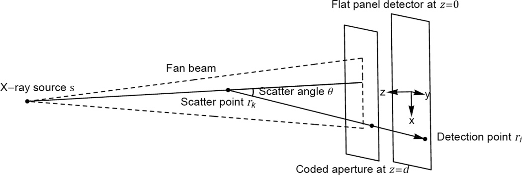
The forward model describes the dependence of measurements on the unknown object parameters. Forward models describing x-ray scatter measurements have been developed before [4, 24–27]. Figure 1 shows the coordinate system used to describe each scattering event. Our detector defines the plane z = 0 while the fan beam propagates in the plane y = 0. The coded aperture defines the plane z = d and implements the transmission function T(r) defined by Eq. (1). The object is positioned between the source and coded aperture and is represented by density f(r) and scattered radiance b(θ), where θ is the scatter angle. Here, the radiance b(θ) is treated empirically but is theoretically proportional to , where E is the x-ray energy, P is the power spectral density of the detected x-rays, and is the differential scattering cross section of the material under investigation.
Fig. 1.
Coordinate system diagram showing a single scattering event.
We ignore multiple scattering effects and assume that b(θ) is valid for all points in the object. The integer j indexes each exposure so that the measured irradiance at point r on the detector during frame j is
| (2) |
where 𝒱 is the volume of the beam and fj(r) is the object’s exposed scattering density for frame j. This model applies to imaging a 3D static density fj(r) = f(x, y − yj, z) by selecting a sequence of object planes y = yj for each exposure (e.g. by linear translation), as well as imaging a dynamic density f(x, z, tj) by choosing the observation times tj. The latter technique is demonstrated in this work. The factorization of fj (r′) b(θ) is appropriate for objects consisting of a uniform, amorphous material, and is a good description of our objects.
The forward model (2) represents the linear transformation between the scattering density fj(r)b(θ) and the irradiance gj(r) at frame j. The detector pixels are centered at the coordinates ri in the plane z = 0. The discrete measurements form the matrix g with components
| (3) |
The function fj(r) is represented as a superposition of point scatterers:
| (4) |
where δ(·) is the Dirac delta function, rk = (xk, zk) is a set of 2D vectors defining the sampling of the object in the plane of the beam, k is a parametric index, and fkj are the density samples to be estimated. The point-like sampling for the object and detector simplifies the computation compared to other representations (e.g. Fourier, Haar, wavelets, etc.). Using (3) and (4) with (2),
| (5) |
where is the scatter angle for the ray connecting object point rk and detector point ri. We define the scattering matrix B with components Bik = b (θik) and the geometry matrix G with components . Equation (5) is written in matrix form as
| (6) |
where ․* represents element-wise multiplication and f is the density matrix with components fkj.
The angle dependence b(θ) was sampled using the Π function (Π(x) = 1 if |x| < 1/2 and Π(x) = 0 otherwise). We consider scatter angle bins indexed by l and centered at θl with widths Δθl:
The coefficients bl form the vector b and were determined by the reconstruction along with f by inverting (6).
Reconstruction algorithm
The forward model was used with Maximum Likelihood Estimation (MLE) [28] to obtain our results. We assume independent Poisson noise at each detector pixel. The components of the measurement vector y are distributed with mean values given by the corresponding components of g, plus a measured background g0:
Define the single vector containing all unknown parameters as x = (f, b), and Let P(y|x) be the probability of observing y given object coefficients x. By enforcing ∂P(y|x)/∂x to vanish in order to achieve a maximum likelihood, we obtain the condition
| (7) |
where x is a vector of ones with the same size as x. This suggests the iterative update
since this will stabilize when condition (7) is met. Define the vectors Πik with components indexed by l. For the vectors f and b, the iterative update steps are
| (8) |
| (9) |
The forward model and reconstruction algorithm were coded in MATLAB and updates were alternated between f and b using Eqs. (8) and (9) to produce our results.
System design and resolution
Imaging in the range direction z is achieved by the harmonic code in the y direction. A point scatterer at range z casts a shadow with N = Y υ(z − d)/z sinusoid periods, where Y is the observable length of the shadow in the y direction. Signals from two point scatterers separated by a distance Δz lose orthogonality for values less than ΔN = 1. Propagating this uncertainty to z through gives range resolution
| (10) |
Transverse imaging relies on distinguishability of the shift code when translated in the x direction. Translation of a scatter point from (x, z) → (x + Δx, z) shifts the shadow by one code period when
| (11) |
which is the equation for transverse resolution, assuming the complete code sequence is observed in the x direction.
The resolution is defined here as the minimum detectable separation between two point scatterers. The imaging resolution is limited by the feature size of the coded aperture and the sampling rate of the scatter signal at the detector. The resolution of any x-ray detector is limited by the interaction length of the x-rays and the detector material. Thicker materials provide increased stopping power with the side effect of pixel cross-talk, particularly for large incidence angles. A similar argument relates the resolution of the coded aperture with its thickness, which we found to be the limiting factor for our setup.
3. Experiment setup and methods
Configuration
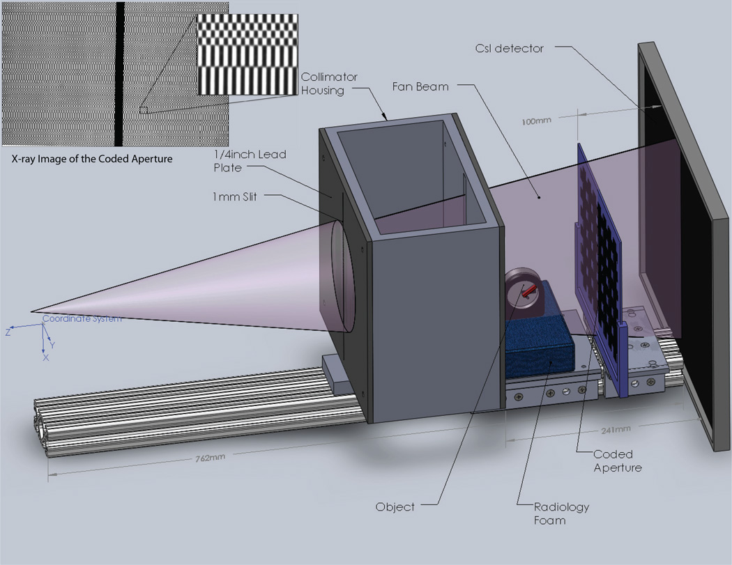
The fan beam assembly for this demonstration utilized an x-ray system developed for breast CT [29] at the Multi-Modality Imaging Laboratory at Duke University. Figure 2 shows a diagram of the modified system including the fan beam collimator, alignment rail, coded aperture, and detector. This drawing also shows an object stage made from foam and a clock we used to demonstrate scatter video. The collimated fan beam illuminated the object and x-rays scattered due to atomic interactions. The scattered x-rays were transferred by the coded aperture, under ray optics, to the detector plane where the scatter images were acquired.
Fig. 2.
Diagram of the experimental system
Acquisition
The Varian Rad-94 x-ray tube was operated at generator settings of 120 kV, 25 mA, and a 400 ms pulse duration. The focal spot had a width of 0.4 mm and was stationed 775 mm from the detector plane. The source was spatially filtered by a series of lead collimators to produce a fan beam with 1 mm width and a full-angle divergence of 0.3° at the object stage. A flat panel scintillation detector (Varian 4030E) detected scattered x-rays with a 406 mm by 293 mm active area and 0.127 mm pixel pitch. The coded aperture was placed parallel to the detector at a distance d = 100 mm. At the intersection of the fan beam and the detector, a strip of lead (100 × 10 × 3 mm) blocked the primary beam. This beam stop prevented the primary beam from saturating the detector, and allowed for full sensitivity to the relatively weak scatter signal. All devices in the apparatus other than the source and detector were oriented along an 80/20 rail. Devices on the rail included the coded aperture, stage for the object, and a two-stage collimator that formed the fan beam. Each of these devices could be moved linearly along the z-direction but remained fixed for the experiments.
Aperture fabrication
The coded aperture was modeled in MATLAB and a mold was printed on an Objet Eden 333 printer. The mold was filled with tungsten powder (grain size > 50 µm) and sealed with epoxy. The mold was 1.35 mm deep with 0.3 mm plastic backing for support, and the filling process produced tungsten features about 1 mm thick (z) with minimum feature size 1.25 mm in x and 0.75 mm in y. The code area was 160 mm (x) by 200 mm (y). The plastic caused negligible attenuation of the x-rays compared with the tungsten features.
Model calibration
To ensure model accuracy, we experimentally determined the position of the x-ray anode. We placed the coded aperture parallel and at several known ranges from the detector. Next, we used ray tracing from paired aperture and image points to triangulate the position of the source and found an offset of s = (2.1, 12.8, 774.8) mm relative to the center of the detector. The source position information was then used to orient the fan beam perpendicular to the detector.
To avoid systematic errors in aperture placement, an empirical measurement of T(x, y) was used in the forward model. Several x-ray projections of the coded aperture were acquired and averaged into a single image to reduce the effect of noise. The averaged image represented the transmission function T(x, y) by using known information: the image’s magnification, the source position, and the aperture-detector distance d.
Test objects
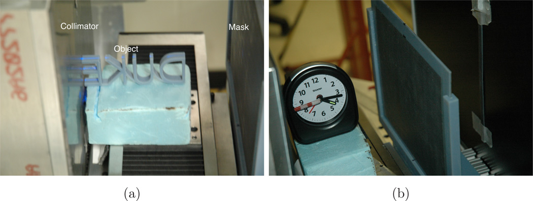
We chose to image plastic objects because they have strong scattering cross sections and the lack of long-range order produces cylindrically symmetric scattering profiles, as was assumed in Sec. 2. To demonstrate snapshot 2D imaging we formed the letters ”DUKE” with our Objet printer. To demonstrate tomographic video, we used a clock with plastic hands. Figures 3a and 3b show the plastic DUKE letters and the clock in position for the experiments. Both were aligned parallel to the fan beam. The DUKE letters covered an area of 100 mm by 40 mm and were 5 mm thick in the y direction, though the beam only illuminated a 1 mm slice. Only the second hand of the clock was exposed to x-rays for that part of the experiment.
Fig. 3.
Photos of (a) plastic DUKE letters and (b) the clock in position for the experiments.
4. Results
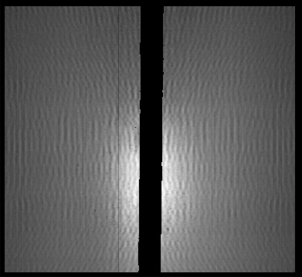
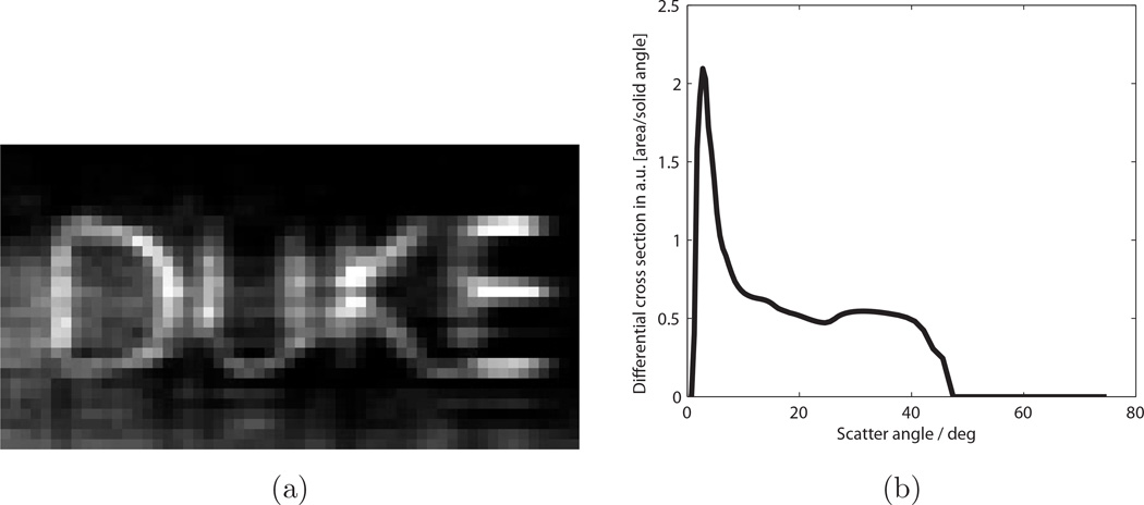
Figure 3a shows the DUKE letters in place for the experiment, and Fig. 4 shows the scatter image acquired for the DUKE object. The primary beam was blocked by a lead strip positioned on the detector, and this region has been blacked out in the image. The scatter image was binned by 3 × 3 pixels in software to reduce memory requirements cropped to prevent the beam stop and pixel defects from affecting the images. Figure 5 shows reconstructions of the scattering density f(x, z) and the scattered radiance b(θ) for this object. Twenty iterations were run with 200 updates for f(x, z) and 5 updates for b(θ) at each iteration. The density image was reconstructed with 2 mm sampling in x and z and the radiance was sampled non-uniformly with 0.5° resolution at θ = 0.5° and up to 4° resolution at θ = 75°. The image shows recognizable letters. Blurring occurred mainly in the range direction (z) since the high-angle scatter, which carries the most range information, was relatively weak and affected by noise. The radiance consists of a low-angle coherent scatter component with a broad tail resulting from high-angle Compton scattering.
Fig. 4.
Cropped and binned scatter image for the plastic DUKE letters, corresponding to a 4.9 cm × 4.5 cm detection area.
Fig. 5.
Reconstructed images for DUKE letters. (a) Density image f(x, z), with x = vertical and z = horizontal. (b) Reconstructed scatter radiance b(θ).
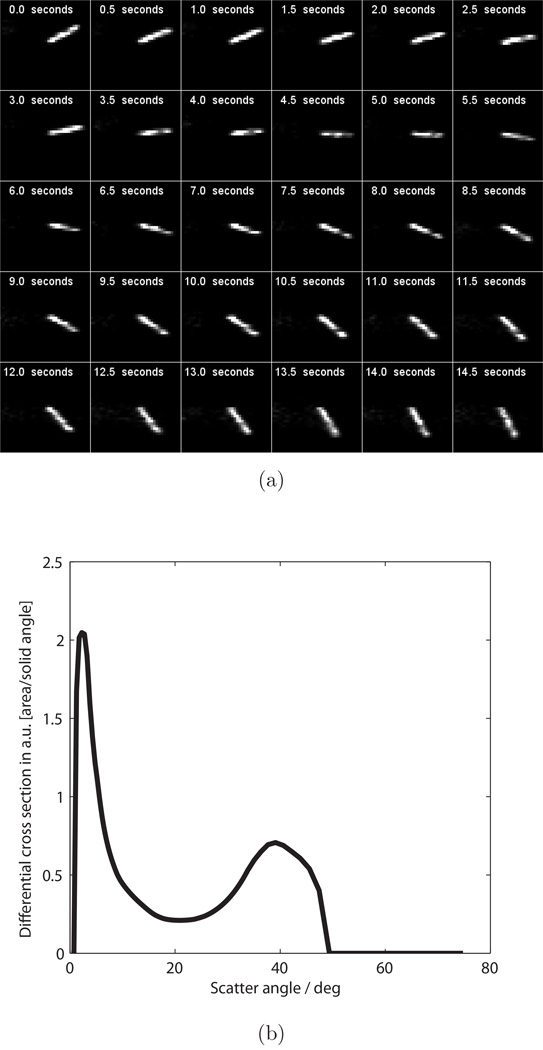
Since every snapshot produces a 2D slice of an object at one moment in time, we used the clock to demonstrate tomographic video. We positioned the clock shown in Fig. 3b so that its second hand ticked in the plane of the beam. A strip of plastic 2 mm thick in the y direction was attached to the second hand so that it was the only object in the beam. As the hand ticked at 1 Hz, scatter images were acquired at 2 Hz. A total of 30 scatter images (not shown) were acquired over a span of 15 seconds. Each frame was used to estimate an instantaneous density image f(x, z). The reconstructed frames are shown with timestamps in Fig. 6a, and as a downloadable video file1. The complete set of scatter images was used to jointly estimate b(θ) for this object, shown in Fig. 6b. We expected this curve to vary from Fig. 5b since each object was made from a different plastic, however model error may also contribute.
Fig. 6.
Reconstructions of the clock’s second hand. (a) Reconstructed density images f(x, z, t), with x = horizontal and z = vertical. Each frame is labeled with the timestamp. (b) Reconstructed scatter radiance b(θ).
The resolution equations (10) and (11) show the importance of a high-resolution coded aperture. Our aperture was built with 1/u = 1.25 mm and 1/υ = 0.75 mm with a resolution target of (Δx,Δz) = (2.5 mm, 2.5 mm) at z = 200 mm. This assumes that the observable scatter image has length Y = 120 mm. During reconstruction, we found our 2D aperture transmission function to introduce modeling errors at high incidence angles and so we cropped the detector to X ≈ 49 mm and Y ≈ 45 mm. Cropping in x only narrows the transverse field of view, however cropping in y theoretically degrades the range resolution to Δz = 6.7 mm, a slight overestimate judging from our reconstructions.
5. Discussion
These results demonstrate the basic utility of our coded aperture design for snapshot tomography. A more detailed analysis is required to resolution limits and signal to noise ratio of the fan beam CAXSI system. We plan more detailed evaluation of source voltage and current parameters, spectral filtering, and imaging of complex and non-uniform objects.
Previous work on snapshot tomography used a pinhole aperture and a detector placed parallel to a fan beam [11]. The range sensitivity of our aperture-detector arrangement allows us to capture forward and/or backscatter signals, as long as the aperture and detector are placed perpendicular to the beam. This flexibility is useful when one side of the object is not accessible, or when only the forward scatter component is strong enough to measure.
The bilinear forward model in Eq. (2) captures only the basic physics of the system. We omitted multiple scattering effects, which include attenuation of the primary beam and scattered rays within the object. We assumed a perfect irradiance detector with uniform energy response. We also assumed a planar coded aperture, but more careful modeling of its 3D structure is needed for high incidence angles. We modeled point-like sampling in space and time for each detector pixel, but a more sophisticated scheme would include their response functions. We represented the object as a superposition of point scatterers, but other choices are possible. More detailed modeling of these effects should improve the quality of the reconstructed images, and is planned for future work.
Given x-ray energies of 20–125 keV, the dominant types of interactions are coherent (Bragg) scattering, incoherent (Compton) scattering, and photoelectric absorption. We used only the coherent and incoherent scatter signals to produce our results. Moving forward, we plan to capture the attenuation signal at θ = 0 and use this measured photoelectric absorption to inform the reconstruction. By measuring contributions from each type of x-ray interaction and comparing with a reference library of cross sections, we hope to determine distributions of constituent materials within an extended and/or dynamic object.
Acknowledgments
This work was supported by the Department of Homeland Security, Science and Technology Directorate through contract HSHQDC-11-C-00083. M.P.T. is also partly supported by NIH R01 CA96821 from which the basis x-ray system was developed.
Footnotes
References
- 1.Kak AC, Slaney M. Principles of Computerized Tomographic Imaging. IEEE Press; 1988. [Google Scholar]
- 2.Lale PG. The examination of internal tissues, using gamma-ray scatter with a possible extension to megavoltage radiography. Physics in medicine and biology. 1959;4:159. doi: 10.1088/0031-9155/4/2/305. [DOI] [PubMed] [Google Scholar]
- 3.Harding G, Kosanetzky J. Scattered x-ray beam nondestructive testing. Nuclear Instruments and Methods in Physics Research Section A: Accelerators, Spectrometers, Detectors and Associated Equipment. 1989;280:517–528. [Google Scholar]
- 4.MacCabe K, Krishnamurthy K, Chawla A, Marks D, Samei E, Brady D. Pencil beam coded aperture x-ray scatter imaging. Optics Express. 2012;20:16310–16320. [Google Scholar]
- 5.Harding G, Kosanetzky J. Elastic scatter computed tomography. Physics in Medicine and Biology. 1985;30:183. doi: 10.1088/0031-9155/30/2/008. [DOI] [PubMed] [Google Scholar]
- 6.Harding G. X-ray scatter tomography for explosives detection. Radiation Physics and Chemistry. 2004;71:869–881. [Google Scholar]
- 7.Madden RW, Mahdavieh J, Smith RC, Subramanian R. Optical Engineering+ Applications. International Society for Optics and Photonics; 2008. An explosives detection system for airline security using coherent x-ray scattering technology; p. 707915–707915. [Google Scholar]
- 8.Stokes J, Alvar K, Corey R, Costello D, John J, Kocimski S, Lurie N, Thayer D, Trippe A, Young J. Some new applications of collimated photon scattering for nondestructive examination. Nuclear Instruments and Methods in Physics Research. 1982;193:261–267. [Google Scholar]
- 9.Davidson MT, Batchelar DL, Velupillai S, Denstedt JD, Cunningham IA. Laboratory coherent-scatter analysis of intact urinary stones with crystalline composition a tomographic approach. Physics in medicine and biology. 2005;50:3907. doi: 10.1088/0031-9155/50/16/017. [DOI] [PubMed] [Google Scholar]
- 10.Van Uytven E, Pistorius S, Gordon R. An iterative three-dimensional electron density imaging algorithm using uncollimated compton scattered x rays from a polyenergetic primary pencil beam. Medical physics. 2007;34:256. doi: 10.1118/1.2400835. [DOI] [PubMed] [Google Scholar]
- 11.Grubsky V, Romanov V, Patton N, Jannson T. SPIE Optical Engineering+ Applications. International Society for Optics and Photonics; 2011. Compton imaging tomography technique for nde of large nonuniform structures; p. 81440G–81440G. [Google Scholar]
- 12.Ables J. Fourier transform photography a new method for x-ray astronomy. Proceedings of the Astronomical Society of Australia. 1968;1:172. vol. 1. [Google Scholar]
- 13.Dicke R. Scatter-hole cameras for x-rays and gamma rays. The Astrophysical Journal. 1968;153:L101. [Google Scholar]
- 14.Brady DJ. Optical imaging and spectroscopy. Wiley-OSA; 2009. [Google Scholar]
- 15.Golay MTE. Multi-slit spectrometry. JOSA. 1949;39:437–437. doi: 10.1364/josa.39.000437. [DOI] [PubMed] [Google Scholar]
- 16.Harwit M, Sloane NJ. Hadamard transform optics. 1979;1 doi: 10.1364/AO.15.000107. [DOI] [PubMed] [Google Scholar]
- 17.Mende S, Claflin E, Rairden R, Swenson G. Hadamard spectroscopy with a two-dimensional detecting array. Applied optics. 1993;32:7095–7105. doi: 10.1364/AO.32.007095. [DOI] [PubMed] [Google Scholar]
- 18.Mrozack A, Marks DL, Brady DJ. Coded aperture spectroscopy with denoising through sparsity. Optics Express. 2012;20:2297–2309. doi: 10.1364/OE.20.002297. [DOI] [PubMed] [Google Scholar]
- 19.Gehm M, John R, Brady D, Willett R, Schulz T, et al. Single-shot compressive spectral imaging with a dual-disperser architecture. Opt. Express. 2007;15:14013–14027. doi: 10.1364/oe.15.014013. [DOI] [PubMed] [Google Scholar]
- 20.Wagadarikar A, John R, Willett R, Brady DJ. Single disperser design for coded aperture snapshot spectral imaging. Applied optics. 2008;47:B44–B51. doi: 10.1364/ao.47.000b44. [DOI] [PubMed] [Google Scholar]
- 21.Kittle DS, Marks DL, Brady DJ. Design and fabrication of an ultraviolet-visible coded aperture snapshot spectral imager. Optical Engineering. 2012;51:071403–1. [Google Scholar]
- 22.Choi K, Brady DJ. SPIE Optical Engineering+ Applications. International Society for Optics and Photonics; 2009. Coded aperture computed tomography; p. 74680B–74680B. [Google Scholar]
- 23.Gottesman SR, Fenimore EE. New family of binary arrays for coded aperture imaging. Appl. Opt. 1989;28:4344–4352. doi: 10.1364/AO.28.004344. [DOI] [PubMed] [Google Scholar]
- 24.Arendtsz NV, Hussein EM. Energy-spectral compton scatter imaging. i. theory and mathematics. Nuclear Science, IEEE Transactions on. 1995;42:2155–2165. [Google Scholar]
- 25.Farmer F, Collins M. A new approach to the determination of anatomical cross-sections of the body by compton scattering of gamma-rays. Physics in medicine and biology. 1971;16:577. doi: 10.1088/0031-9155/16/4/001. [DOI] [PubMed] [Google Scholar]
- 26.Carlsson CA. Imaging modalities in x-ray computerized tomography and in selected volume tomography. Physics in medicine and biology. 1999;44:R23. doi: 10.1088/0031-9155/44/3/011. [DOI] [PubMed] [Google Scholar]
- 27.Batchelar DL, Cunningham IA. Material-specific analysis using coherent-scatter imaging. Medical physics. 2002;29:1651. doi: 10.1118/1.1493216. [DOI] [PubMed] [Google Scholar]
- 28.Lange K, Carson R, et al. Em reconstruction algorithms for emission and transmission tomography. J. Comput. Assist. Tomogr. 1984;8:306–316. [PubMed] [Google Scholar]
- 29.Crotty DJ, McKinley RL, Tornai MP. Experimental spectral measurements of heavy k-edge filtered beams for x-ray computed mammotomography. Physics in medicine and biology. 2007;52:603. doi: 10.1088/0031-9155/52/3/005. [DOI] [PMC free article] [PubMed] [Google Scholar]


