Abstract
Gastric cancer is the second leading cause of cancer death worldwide and screening programs have had a significant impact on reducing mortality. The majority of cases occur in low- and middle-income countries (LMIC), where endoscopy resources are traditionally limited. In this paper, we introduce a platform designed to enable inexpensive gastric screening to take place in remote areas of LMIC. The system consists of a swallowable endoscopic capsule connected to an external water distribution system by a multi-channel soft tether. Pressurized water is ejected from the capsule to orient the view of the endoscopic camera. After completion of a cancer screening procedure, the outer shell of the capsule and the soft tether can be disposed, while the endoscopic camera is reclaimed without needing further reprocessing. The capsule, measuring 12 mm in diameter and 28 mm in length, is able to visualize the inside of the gastric cavity by combining waterjet actuation and the adjustment of the tether length. Experimental assessment was accomplished through a set of bench trials, ex vivo analysis, and in vivo feasibility validation. During the ex vivo trials, the platform was able to visualize the main landmarks that are typically observed during a gastric cancer screening procedure in less than 8 minutes. Given the compact footprint, the minimal cost of the disposable parts, and the possibility of running on relatively available and inexpensive resources, the proposed platform can potentially widen gastric cancer screening programs in LMIC.
Keywords: Gastric cancer screening, robotic endoscopy, capsule endoscopy, waterjet actuation, global health
I. Introduction
ORLDWIDE, gastric and esophageal cancers account for over 10% of incident diagnoses, totaling 1.4 million cases annually [1]. In addition, gastric cancer and esophageal cancer have the second (10%) and sixth (5.4%) highest global mortality rates respectively [1]. While both types of cancer are global phenomena, nearly 70% of cases are concentrated in low- and middle-income countries (LMIC) [2], [3]. Screening programs have been shown to be effective in reducing the mortality rate through early detection [4]–[7].
Typically, screening for gastric and esophageal cancer is completed using a flexible endoscope. While flexible endoscopes are used reliably in modern medical settings, many issues hinder their usage in LMIC. First among these issues is a lack of ability to reliably reprocess the endoscopes after each procedure [8]. Improper (or lack of) reprocessing of endoscopic equipment can lead to further spread of harmful bacteria and diseases in areas already plagued by illness.
Capsule endoscopes could provide a sanitary method for upper gastrointestinal (GI) tract cancer screening due to their disposability [9]. Where issues arise for the use of capsule endoscopes in upper GI procedures, is their lack of dynamic controllability [10] and their cost per individual procedure [11]. With the stomach having such a large workspace, direct control of the capsule’s movement is required to accomplish a complete examination. In 2010, Olympus Medical Systems Corp and Siemens Healthcare jointly started development of a wireless, magnetically guided endoscopic capsule (MGEC) for upper GI endoscopy [12]. This platform operates using the magnetic interaction between a small permanent magnet embedded in the capsule and a large magnetic guidance system (footprint of 1m x 2m) to control the capsule with 5 degrees of freedom (DoF) [12]. To reduce friction from the mucosa and to expand the stomach for easier viewing, the patient is asked to drink water prior to the procedure. Each MGEC is designed to be single-use and is disposed of after examination. While use of this platform is promising in modern medical settings, the costs associated with both the external driving unit and each individual capsule would prohibit its adoption in low-resource settings. In addition, any screening program’s ability to reach remote areas would be hindered by the limited portability of the magnetic guidance system due to its large footprint.
Capsule robots have been proposed for inspection of fluidfilled stomachs using a combination of external magnetic guidance and a soft capsule body in [13]–[15], or through usage of a number of propellers as in a miniature submarine in [16], [17]. Again, the limited portability of the guidance system [13] and the cost of the disposable on-board electronics [13], [17] make these solutions not suitable for LMIC.
Any endoscopic platform designed for an upper GI cancer screening program in resource-limited and/or remote areas of LMIC would ideally need to be easily controllable within both the esophagus and stomach, be portable to easily move from each remote location to the next, be mechanically reliable, be disposable for sanitation purposes, and be able to operate at minimal cost per procedure (i.e., 2-5 USD). With procedural costs in mind, any on-board system electronics, such as cameras, would need to be reclaimable and not require any further reprocessing.
Proposed for the first time in this paper is a disposable, soft-tethered, swallowable endoscopic capsule, referred to as the Hydrojet capsule (Fig. 1), which has the potential to enable inexpensive gastric cancer screenings to take place in remote areas of LMIC. If patients in a remote area are found to have any suspicious lesions or any other noticeable physical discrepancies after a Hydrojet procedure, the physician would then be able to more reliably refer them to a less remote healthcare setting for a traditional gastroscopy. Water – a resource relatively available and inexpensive in most remote settings – is pressurized and ejected from the capsule to orient the view of the endoscopic camera. After completion of a cancer screening procedure, the Hydrojet outer shell and tether is disposed of and the capsule’s camera is reclaimed without needing further reprocessing. This capsule configuration has the potential to minimize procedural cost and reduce the risk of spreading disease through improper reprocessing of endoscopic tools. Additionally, since the setup needs to be easily transported from one location to the next, the entire system has been designed with portability in mind.
Fig. 1.
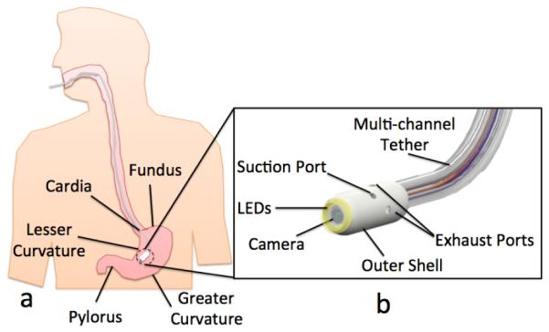
(a) The Hydrojet capsule inside a human stomach with gastric landmarks; (b) Labeled rendering of the Hydrojet capsule.
II. Principle of Operation
The proposed platform consists of a swallowable capsule connected to external water distribution and vision acquisition systems by a disposable, multi-channel, soft tether. As represented in Figs. 1.b and 2, the capsule is first comprised of a disposable outer shell with two fluid suction ports and four fluid exhaust ports. The exhaust ports, placed in 90° intervals around the capsule’s cylindrical body and oriented at 90° relative to the capsule’s axial direction, allow the Hydrojet to achieve two-DoF motion when pressurized water is expelled from them. Through selective activation of the exhaust ports at varying water pressures, the Hydrojet is able to operate in a quasi-hemispherical region. A third DoF can be introduced to the system through the feeding and retraction of the attached multi-channel tether. Suction ports allow the operator to control the amount of fluid within the subject’s stomach during a procedure. On the front side of the Hydrojet’s outer shell is a viewing window for the internal camera. Connection points for the multi-channel tether are housed in the rear of the capsule. As illustrated in Fig. 2.a, the Hydrojet’s inner core module contains the endoscopic camera and LEDs. A four-pole female connector is located on the backside of the inner core. This module rests within a waterproof cavity inside the Hydrojet’s outer shell. The inner core module is easily inserted or removed from the Hydrojet’s outer shell prior to and following a procedure respectively, allowing the on-board electronics to be reclaimed and reused. The multi-channel tether is composed of six independent flexible tubes. Four of these tubes supply pressurized water to their respective Hydrojet exhaust ports. A fifth tube is used for liquid removal and attached to the suction line on the capsule. The final sixth tube holds the electrical wiring for the vision unit and is plugged into the connector located on the backside of the inner core.
Fig. 2.
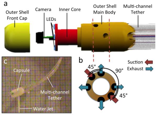
(a) Exploded view of the Hydrojet capsule; (b) Orientation of Exhaust and Suction Ports; © Hydrojet capsule using water jet actuation in air.
To provide pressurized water for capsule maneuverability, an external water distribution system consisting of a network of pumps, valves, flowmeters, and junction manifolds is proposed. Referring to the block diagram in Fig. 3, water is transferred by a pump from a reservoir tank into the first of two system manifolds. From the first manifold, water either exits through the mainline to be distributed further downstream into the system or is returned back into the initial holding reservoir. The amount of water allowed to return to the reservoir tank determines the water pressure level downstream in the system. To vary this amount and, thus, alter the exit pressure of the water through the Hydrojet’s exhaust ports, multiple secondary water lines exit the first manifold. Each line has its own independent solenoid valve which is directly connected to the Hydrojet’s control system. In the current implementation of the platform, we have two exit lines that allow the main pressure to be reduced either by a factor of two or ten in case one or both lines are open, respectively. Additional exit lines can be introduced to achieve a finer control in water pressure.
Fig. 3.
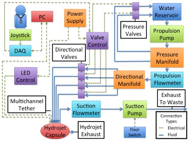
Block diagram of the Hydrojet system.
Water that exits the first manifold through the mainline then enters into a flowmeter (Propulsion Flowmeter in Fig. 3). This flowmeter allows for tracking of the amount of water exhausted by the capsule and to monitor how much fluid has been introduced into the patient’s stomach. Exiting the flowmeter, pressurized water then travels into the directional manifold that distributes it to four lines on the multi-channel tether. Activation and deactivation of these lines via dedicated solenoid valves dictates the motion of the Hydrojet by controlling which exhaust port on the capsule receives pressurized water. Fluid removal from the patient is accomplished through a completely isolated line within the multi-channel tether and is operated by user activation of a suction pump. A dedicated flowmeter allows the operator to monitor the amount of fluid removed and, in conjunction with the first flowmeter, the net amount of fluid expended during operation.
An external joystick, in conjunction with vision relayed by the Hydrojet, allows for open-loop control of water distribution, and therefore capsule movement, by the operator. To control the exit pressure of the water, a button on the joystick cycles through valve settings. The suction line pump is controlled using a foot pedal. A graphical user interface (GUI) on the personal computer (PC) allows the operator to see the current operating direction and exit pressure. The GUI also shows the exhaust line flow rate, suction line flow rate, and net liquid used within the patient. Using data provided by both the suction and propulsion flowmeters, the GUI will also alert the operator when the net fluid introduced into the stomach exceeds safety thresholds. The operator then will know to cease propulsion and to activate the suction line until once again under the safety threshold. A second, dedicated monitor provides the view from the capsule’s on-board camera.
III. System Design and Fabrication
A. Medical Considerations and Technical Requirements
In designing the Hydrojet platform, the following medical considerations have been taken into account.
1) Device introduction is accomplished through oral insertion.
Therefore, the Hydrojet must be able to pass through the esophagus. This passage in a fully grown adult, as measured from the esophogeal sphincter, is approximately 18-26 cm in length and 2-3 cm in diameter [18]. This is a limiting factor in the allowable diameter of the device. Standard gastroscopes are up to 1.1 m in length and 12.8 mm in diameter [19].
2) Internal Workspace. A typical non-distended human stomach has an average volumetric capacity of approximately 1,000 cm3 [20]. On average, the stomach has a maximum width of 10 cm and a length of 34 cm at the greater curvature [21]. To operate within the workspace, flexible endoscopes use Bowden wires to mechanically move the distal camera with two angular DoFs. To look backward to the cardia and the fundus, flexible endoscopes are capable of retroflexion, a process where the tip of the endoscope is deflected 180° by the user.
3) Fluid Control. The Siemens/Olympus MGEC system uses a protocol where the patient drinks a total of 1.3 L of water prior to the procedure [12] to expand the stomach. This volume can be assumed as a safety threshold not to be exceeded during operation of the Hydrojet platform. To achieve this goal, fluid levels must be monitored and controlled in real time.
4) Duration of Procedure. A standard upper GI endoscopy takes from 5 to 15 minutes [22]. Therefore, the Hydrojet must allow the operator to visualize the main anatomical landmarks in a comparable amount of time. In terms of maximum duration of a single procedure, the Hydrojet must guarantee uninterrupted operation for at least 75 minutes (i.e., safety factor of five applied to the 15 minutes duration).
5) Disposability and Cost. As the target application is upper GI screening in LMIC, the costs related to a single procedure must be minimized (i.e., 2-5 USD). This can be achieved by disposing plastic parts of the instrument, while retaining electronic components without the need for reprocessing them.
6) Portability. To enable upper GI screening programs to reach remote areas and operators to move from one village to the next, the system must be easily portable and should run on available and inexpensive resources.
7) Safety. To prevent tissue damage, the exhaust pressure at each nozzle must remain below 3 bar [23]. Regarding temperature of operation, the capsule must remain below 34°C [24] to ensure no tissue damage occurs in the esophagus or stomach during introduction or examination, respectively. In the case of all tether lines detaching from the main body, the capsule must be designed with size constraints in mind to pass through the lower GI tract using peristalsis (i.e., a maximum size of 13 mm in diameter and 31.5 mm in length, as commercial capsule endoscopes [25]).
B. Waterjet Actuation System – Design and Fabrication
1) Hydrojet Capsule. Made from a durable plastic (Objet Verowhite Plus) via 3D printing (Objet Geometries Ltd, Model: OBJET 30), the outer shell has a diameter of 12 mm, length of 28 mm, and weight of 2.7 g. The current material is not biocompatible as only the feasibility of the present device is being assessed at this stage. Nevertheless, the design is compatible with injection molding of biocompatible plastic materials. On the aft of the Hydrojet, five tether connections ports were created (diameter 3.4 mm) to allow insertion of the propulsion and suction tubes. In the center of the Hydrojet’s aft, another port was created (diameter 2 mm) for insertion of the sixth central line to power the on-board electronics. On the outer shell external surface, 16 mm from the front face of the capsule, four exhaust ports (diameter 2 mm) were placed in 90° intervals around the capsule’s longitudinal axis. The point of placement of these ports corresponds to the Hydrojet’s theoretical center of mass when loaded with the inner core module. Two additional ports (diameter 2 mm) were placed with 180° spacing around the outer shell surface at 12 mm from the front face of the Hydrojet for the suction line. The symmetrical placement of suction ports allows the overall disturbance created by liquid suction to be a negligible factor when operating the Hydrojet. The port placement is represented in Fig. 2.b. On the front side of the capsule, a recess (diameter 7 mm, depth 0.8 mm) was created to place a plexiglass cover to shield the inner core from the external environment.
The inner core module, also fabricated by rapid prototyping, has a diameter of 5.4 mm and a length of 17 mm, and contains the on-board camera, LEDs, and a four-pole female connector on the backside. The dimensions of the inner core allow it to be inserted and removed from a recess within the outer shell without it ever contacting the external environment. The entire capsule with both inner core and outer shell is designed to be waterproof and neutrally buoyant when in water.
2) Multi-channel Tether. To connect the capsule to the water distribution and visual acquisition systems, six independent tubes, each measuring 1.1 m in length, were used. Five of these tubes (Tygon PVC Tubing, 3.18 mm outer diameter (OD), 1.59 mm inner diameter (ID)) are used by the water distribution system. The sixth tube (Miniature Clear EVA Tubing, 1.78 mm OD, 1.02 mm ID) nests in the center of the five larger tubes and provides the wired connections to the capsule’s electronics for power and video transmission.
3) Water Distribution System. To provide pressurized water to the system, a positive displacement three-chamber diaphragm pump (ShurFlo, Model: 8030-863-239) was used to take in water from a reservoir upstream. Immediately downstream from the pump, pressurized water was fed into the system’s first brass manifold which has two side outlets. These side outlets are connected by polyvinyl-chloride (PVC) tubing (6.35 mm OD, 3.18 mm ID) to their own respective stainless steel solenoid valves (McMaster-Carr, Model: 5077T144). Downstream from the first manifold, an ultrasonic flow meter was attached to the system (Titan, Model: Atrato 740-V20-A) and connected directly to the system’s data acquisition (DAQ) board (National Instruments, Model: NI-USB-6221) for monitoring the total amount of fluid expelled from the capsule. Further downstream is the system’s second brass manifold with four side outlets. The same model of valves (McMaster-Carr, Model: 5077T144) and PVC tubing (6.35 mm OD, 3.18 mm ID) were used to provide directional control to the Hydrojet. To activate both the pressure control and the directional control valves, power was regulated via a valve control box, which was comprised of multiple NPN transistor gates driven by the DAQ board. The valves were regulated via On/Off signals due to their relatively slow commutation time (i.e., 20 ms). Finer control of capsule motion may be achieved via independent pulse width modulation (PWM) of the pressure at exhaust ports, as suggested in [26]. While this can be obtained by using faster and more expensive valves, we hypothesized that three different levels of pressure, combined with the field of view of the camera and the adjustment of tether length, were sufficient to inspect the surface of the stomach, while minimizing the overall cost of the platform. The validity of this assumption was assessed in both ex vivo and in vivo trials described in section IV. Larger diameter PVC tubing (12.7 mm OD, 9.58 mm ID) was used between the reservoir, pump, flowmeter, and manifolds so as not to inhibit the max allowable flow rate to the Hydrojet.
To operate the suction line, another positive displacement pump (ShurFlo, Model: 8000-912-288) was used. A Pelton wheel flowmeter (Cole-Parmer, Model: W-32709-80) was attached upstream from the displacement pump and connected to the DAQ board to monitor the outflow of fluid from the patient during procedure.
All parts of the water distribution system were chosen with portability and cost in mind. In particular, the total cost of the listed components is under 6,000 USD.
4) Static Analysis. Prior to bench testing the system, the force needed at the exhaust ports to achieve a particular angular orientation of the camera at various tether lengths was estimated via static analysis. Tether length is originally measured from the cardia as it is considered the point of origin within the stomach and acts as an anchor point for the tether. The possible orientation angles of the capsule were deemed to be of significance since, to successfully visualize gastric landmarks, the capsule needs to be able to use the mucosa as a deflection wall. Approaching the mucosa at approximately a 90° angle allows for the capsule to pivot off the mucosal wall with minimal interaction. As represented in Fig. 5 for the transition from configuration 1 to 2, introduction of additional tether length as the capsule is perpendicular to the gastric surface creates a physical pivot point where the tether contacts the mucosal wall. After this contact occurs, it is assumed the capsule is now operating on a newly created tether length. For example, this assumption means that the capsule will behave in a similar manner whether the tether is 6 cm past the cardia or if 6 cm away from a pivot point on the mucosal wall.
Fig. 5.
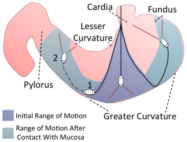
Hydrojet estimated range of motion.
To calculate capsule angular orientation θ, defined as the displacement from the vertical alignments as in the inset in Fig. 6, the method of elliptic integrals was used [27], [28]. To simplify the model, the multi-channel tether was considered to act as a single line. This simplification was calculated using an equivalent area moment of inertia method by first finding the area moment of inertia for each of the six independent tubes of the tether. Through usage of the parallel axis theorem around the centroidal axis of the central tube, the single area moments of inertia were summed to form one governing area moment of inertia. An equivalent dimensioned single tube was found by using the following circle packing equation for five circles within a circle [29],
| (1) |
where d3o is the diameter of the outer multi-channel tubes (i.e., 3.18 mm). A packing of only five circles was used since the smaller central tube was capable of fitting within the interstitial space of the five outer tubes. By using this model, we obtained an equivalent single tube outer diameter of 8.59 mm, while an equivalent single tube inner diameter of 7.25 mm was derived from the previously found equivalent area moment of inertia.
Fig. 6.
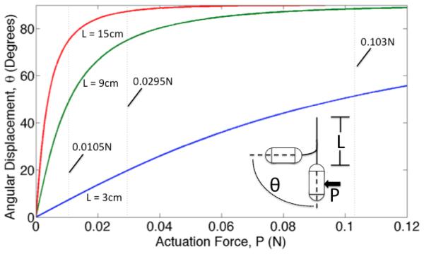
Estimated angular orientation of the Hydrojet capsule as a function of tip actuation force at varying tether length, L. The vertical dashed lines represent the maximum tip actuation forces available in the current platform.
It is worth mentioning that, in the current implementation, the single tubes can slide one against the other and reconfigure during bending. For this reason they offer a lower bending stiffness. Therefore, the modeling we propose here provides a worst-case estimation of the force required to achieve a certain orientation angle.
The system was modeled as a flexible cantilever beam with a point load, representative of the waterjet actuation, on it’s end. Gravity was ignored as an external force since the capsule has neutral buoyancy when in water. The distance from the cardia to the greater curvature was assumed to be around 15 cm, therefore the model was used to investigate beam (tether) lengths L ranging from 3 cm to 15 cm in steps of 3 cm. The values of the complete elliptic integral of the first kind F i(θ) and incomplete elliptic integral of the first kind F ii(θ) can be found via elliptic integral tables and used to derive the modular angle α. Then, the required force P for a given set of bending parameters can be found with
| (2) |
where E is the Young’s Modulus of the tube (4.5 MPa), I is the equivalent area moment of inertia of the single tube, and L is the tether length. The required forces to achieve particular angles on 3 cm, 9 cm, and 15 cm tethers are shown in Fig. 6. The vertical dashed lines on the plot represent the maximum forces at the exhaust port of the capsule for the three different levels of pressure available in the current implementation of the platform. In case of combined motions involving water ejection from two exhaust ports, these forces must be scaled down by a factor of two (i.e., the number of active directional valves). The estimations in Fig. 6 show that, with the design choices that have been made, we can expect to reach any desired orientation angle from 0° to 90° by adjusting the tether length and the water pressure level.
C. Other Components
An ultra-mini color camera (Misumi Electronics Corp, Model: MO-B0804-62) was chosen to be used inside the capsule for its size (4.8 mm diameter, 18.8 mm length), cost (128 USD) and video quality (656x496 resolution, 30 fps, 64° field of view, 1 mm minimum working distance). The camera’s video signal is acquired by a frame grabber (Forward Video Co. Ltd., Model: ezcap116) and displayed on a secondary monitor. Four warm white LEDs (Nichia Corp, Model: NS2L157ART-H3) driven via PWM provide illumination for the camera during the procedure.
A thumb controlled joystick with a center select button (Adafruit, Model: 512) was adopted to maneuver the Hydrojet during the procedure, while National Instrument’s LabVIEW was used to create the control program and the system’s GUI.
IV. Experimental Analysis
A. Bench Testing
1) Force Testing. Quantification of the forces exerted by the expulsion of water was accomplished using a load cell (ATI Industrial Automation, Model: NANO17, resolution 1/160 N). The capsule was connected to the load cell using a 3D printed adapter and a 130 mm steel rod of 4 mm diameter. Multiple tests were completed with the pressure set at low, medium and high settings, operating each single exhaust port one at the time. The average forces exerted by the waterjets were 0.0105±0.0013 N, 0.0295±0.0012 N and 0.103±0.0024 N on low, medium and high settings, respectively. These values are reported as vertical dashed lines in the plot in Fig. 6. The exhaust pressures were calculated to be 0.0334±0.0041 bar, 0.0939±0.0038 bar and 0.328±0.0076 bar for low, medium and high settings. These values are well below the aforementioned safety threshold of 3 bar. We also confirmed experimentally that, when two exhaust ports are activated at the same time, the force drops by a factor of two. The average thrust force from each waterjet when two exhaust ports are simultaneously activated were found to be 0.0048±0.0008 N, 0.0138±0.0013 N and 0.0496±0.0015 N for low, medium and high, respectively.
2) Fluid Flow Rate. Using the system flowmeters, the volumetric flow rate of the Hydrojet exhaust ports was found to be 0.328 L/min, 0.576 L/min and 1.07 L/min respectively for low, medium and high pressures. Using Bernoulli’s equation, exhaust velocities were found to be 2.43 m/s, 3.86 m/s and 5.54 m/s respectively. With the suction line having a fluid removal rate of approximately 0.5 L/min, extensive use of high pressure would require resting periods solely for suction. Using the real-time data acquired by both flowmeters on the suction and propulsion lines, the operator would be alerted when period of resting suction would be required.
3) Range of Motion. Before getting into the details of this experiment, it is worth denoting the difference between the capsule’s range of motion (as represented in Fig. 5) versus the capsule’s range of vision. The capsule’s range of motion is defined as the reachable locations of the capsule’s center of mass during operation. The capsule’s range of vision is defined as the workspace that can be visualized by the operator through the camera mounted in the Hydrojet capsule. Therefore, the range of vision is a larger region than the range of motion and is determined by the capsule’s range of motion, the capsule’s possible angular orientation at a given location and the field of view of the onboard camera.
The capsule’s range of motion and angular orientation were quantified using a 5-DoF magnetic tracking module (Northern Digital Inc. (NDI), Model: Aurora Tabletop Transmitter, 1.2 mm positional nominal root mean square error (RMSE), 0.5°rotational nominal RMSE, 40 Hz update rate) inserted into the capsule at the center of mass and orientated along its longitudinal axis. Rotation about this axis is the only DoF not recorded during the trials. Using a gastric overtube (Guardus, Model: PN00711149) to simulate an esophagus, the capsule with tracker was inserted into a tank of water until a tether length of 3 cm was measured exiting from the overtube and into the tank. The capsule was then propelled in all possible directions on low, medium, and high water pressure settings. After capturing a full range of motion for a 3 cm tether, the capsule was further introduced into the tank in steps of 3 cm additional tether lengths up to 15 cm and the test was repeated each time. Overall displacement of the capsule center of mass under a medium exhaust setting is reported in Fig. 7. While the capsule was propelled in all possible directions, initial pre-bending in the tether either aided or hindered capsule motion depending on whether the capsule was moving with or against the moment created by pre-bending. When operating the capsule on high pressure, the motion became unstable past a 9 cm tether length.
Fig. 7.
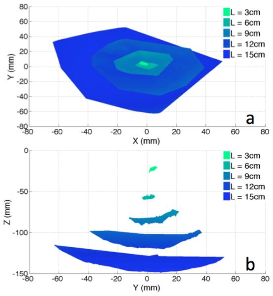
Experimental Range of Motion: (a) Top View; (b) Side View.
From the data acquired by the 5-DoF magnetic tracker, the capsule’s angular orientation θ as defined in Fig. 6 at maximum bending was extracted and then compared to the values estimated by the previously calculated single-tether model. The comparison of these values is shown in Table I. As anticipated, the single tether assumption led to an underestimation of maximum bending angles with an average absolute error of 5.59°±6.46°, which constitutes a percentage error of 13.5%±19.7% across all tether lengths and pressure settings. The large error at the 3-cm tether length is most likely due to the limited resolution of the magnetic tracker. If the 3- cm tether length is disregarded, the average absolute error becomes 3.76°±2.96° with a percentage error of 6.25%±6.75%. 4) Long-Term Reliability. To determine the Hydrojet’s ability to operate for extended periods of time without structural failure, the capsule was subjected to a reliability test. In this examination, the capsule was submerged in a tank of water and operated at random by software with both camera and LEDs turned on. The Hydrojet system was monitored approximately every 30 minutes. After 6 hours of continuous operation, the capsule was removed from the test bench and examined, showing no signs of water leakage into the inner core and no degradation of either the on-board camera or LEDs.
TABLE I.
Capsule Orientation: Maximum Measured Orientation Angles and Absolute Errors
| Actuation Force (N) | ||||||
|---|---|---|---|---|---|---|
| Tether Length |
0.0105 | 0.0295 | 0.103 | |||
|
|
||||||
| Measure | Error | Measure | Error | Measure | Error | |
|
| ||||||
| 3 cm | 17.2° | 9.8° | 44.4° | 24.3° | 50.6° | 1.0° |
| 6 cm | 36.9° | 8.2° | 61.9° | 6.3° | 87.8° | 5.7° |
| 9 cm | 55.4° | 5.5° | 78.1° | 3.0° | 94.3° | 5.9° |
| 12 cm | 65.6° | 0.3° | 86.3° | 2.6° | Unstable | N/A |
| 15 cm | 75.5° | 0.1° | 87.2° | 0.0° | Unstable | N/A |
5) Thermal Analysis. Thermistors (Digikey Corp, NTC 50kΩ 1%, Model: 317-1378-ND) connected to a DAQ board were used to determine the Hydrojet’s operating temperatures. Two points on the capsule were measured during a total of 3 hours of operation. One sampling point was next to the vision module, while the other was at the connection with the multichannel tether. The capsule was submerged in 22°C water at the beginning of the trial and remained submerged for the entire process. After approximately 79 minutes the capsule reached a steady state temperature of 34°C at the front and 33°C at the aft. This temperature profile meets the 34°C limit previously mentioned as temperature safety threshold.
6) Portability. Once assembled, the entire system weighed 17.58 kg and required a footprint area of 0.3136 m2.
B. Ex Vivo Analysis
Ex vivo testing of the Hydrojet was performed in an excised porcine stomach aiming at visualizing the cardia, the fundus, the greater curvature, the lesser curvature, and the pylorus. These landmarks are typically observed during gastric cancer screening procedures [30]. To ensure the capsule properly identifies the points from within the stomach, a series of external laser beams were projected at these particular points. The beams were visible both externally by the operator and internally by the Hydrojet, as represented in Fig. 8. For each trial, the operator was timed as he used the Hydrojet to identify the five anatomical landmarks. Identification of a point of interest was confirmed when the operator saw its respective laser point using the on-board camera. Unlike the suturing of markers or the injection of ink into the stomach wall, use of laser beams allowed for a qualitative assessment of landmark location by the operator without physically compromising the integrity of the porcine stomach. Prior to the ex vivo trial, the placement of landmark points was confirmed by an experienced gastroenterologist.
Fig. 8.
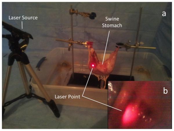
(a) External view of ex vivo setup with the laser source; (b) Internal view of laser beam from the Hydrojet camera.
A single operator controlled the Hydrojet for a total of six complete trials. The operator was allowed to experiment with capsule movement for 20 minutes prior to the trial. A trial was deemed completed once all five points of interest were identified. The average time of trial completion was 6m 15s ± 1m 41s. In every trial, all the five landmarks were identified by the operator. These results fall within typical time ranges of a completed gastroscopy procedure. During each trial, it was also recorded that an average of 1.35L ± 0.4L of water was introduced into the porcine stomach by the capsule. During the procedure fluid was capable of being suctioned at a rate of 0.5L/min ± 0.02L/min. This rate allowed for the platform to operate without exceeding our 1.3 L safety threshold. No trauma to the excised porcine stomach was found after conclusion of the trials. It is worth mentioning that the operator often used the mucosa as a deflection wall to visualize certain landmarks such as the pylorus, the fundus, and the cardia, thus confirming the feasibility of the inspection strategy described in Fig. 5.
C. In Vivo Analysis
After ex vivo validation, an in vivo qualitative feasibility trial on a porcine model (55-kg female Yorkshire swine) was conducted at Vanderbilt University in accordance with all ethical considerations and the regulations related to animal experiments (IACUC protocol M/14/014). The aims of this study were to show capability of capsule introduction into a living subject’s stomach and to qualitatively observe device maneuverability once within the gastric cavity. An attending physician at Vanderbilt (more than 1,000 lifetime flexible endoscopies) was involved in this trial to provide a feedback on usability. To ease device introduction since the animal was under intravenous sedation – thus with reduced esophageal peristalsis – a gastroesophageal overtube was used during the entire procedure (Guardus, Model: PN00711149). Along with the Hydrojet, a gastroscope (Olympus Corp., Model: GIF180) was inserted through the overtube to visualize capsule operation. Capsule and gastroscope operation were accomplished by two different users.
The capsule was successfully introduced through the esophagus into the subject’s stomach using the gastroesophageal overtube. Once within the stomach, the capsule was able to maneuver and relay images using the on-board camera. The mobility achieved by varying the water pressure level at the nozzles and by adjusting the tether length was deemed qualitative comparable to a standard gastroscope. Three consecutive frames representing the Hydrojet motion as observed by the retroflexed gastroscope are shown in Fig. 9. It is worth mentioning that the flow caused inside the stomach by the lateral waterjets, which can be observed in Fig. 9, did not hamper the visualization of the mucosa by the Hydrojet capsule. After the conclusion of the in vivo analysis, the subject was sacrificed and the stomach excised for further analysis. No evidence of significant trauma to the swine was observed either during or after the experiment.
Fig. 9.
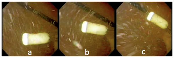
In vivo trials: (a-c) Three consecutive frames acquired by the retroflexed endoscope showing the Hydrojet in motion.
V. Conclusion and Future Work
This paper introduces a low-cost capsule endoscopy platform capable of allowing an operator to conduct a visual assessment of the upper GI tract. The ease of disposability of the capsule and multi-channel tether, along with the reusability of the Hydrojet’s internal camera without needing further reprocessing, would allow it to be used inexpensively in LMIC. Pressurized water flowing through a controlled distribution system was used to propel the Hydrojet in the desired direction of viewing. A model to predict capsule orientation at differing exhaust forces and tether lengths was derived by simplifying the multi-channel tether to an equivalent single tube tether and using elliptic integrals functions. Bench trials were performed to determine the force of water expelled from the capsule at various pressure settings, the capsule’s range of motion, the long term reliability of the capsule in operation underwater, and the capsule’s temperature over extended periods of operation. Ex vivo assessment of the Hydrojet platform was performed using a porcine stomach to quantify the total time needed to visualize anatomical landmarks typically adopted in gastric cancer screening procedures. An in vivo qualitative validation of the Hydrojet confirmed the feasibility of introducing the capsule into a living subject and maneuvering it once in the stomach. The overall cost of the platform is estimated to be below 6,000 USD, with a projected cost per procedure related to the disposable part of the Hydrojet of 2-5 USD. With the entire platform occupying a footprint of 0.157 m2 and weighing 17.58 kg, we can envisage integration into a couple of carry-on sized luggage containers, thus allowing portability in remote regions of LMIC.
Future work first includes refinement of the Hydrojet’s pressure control system. Additional pressure control valves with differing diameters of exhaust tubing would allow for more sensitive control of the Hydrojet. An alternative would be to use faster valves and control the flow via PWM, as long as this does not prohibitively increase the price of the platform.
Occlusion of the suction line did not occur during in vivo operation, however, occlusions due to debris particles within the stomach or due to aspiration of mucosal tissue are a possibility. This is also typical for gastroscopy administered with current flexible endoscopes. The solution we envision in case of occlusion is the same one adopted in current practice, i.e. reversing the pressure of the suction line by flushing saline solution with a syringe.
Another future step is to reduce capsule size from the current 12 mm diameter. This could be accomplished in conjunction with the introduction of a smaller endoscopic camera, such as the micro Scoutcam 1.2mm-diameter camera by Medigus. An improved mathematical model of the Hydrojet’s range of motion should be further investigated to aid in the refinement process.
Use of a gastric overtube allowed the Hydrojet capsule to be introduced into the porcine stomach without any signs of buckling in the multi-channel tether. However, this may become an issue during clinical use, should esophageal peristalsis be insufficient to propel the capsule down to the stomach. In this case, the incorporation of a single, multi-channel tether with progressive stiffness may prevent buckling during insertion.
Additional in vivo trials are planned to confirm the safety of the Hydrojet via post mortem histological analysis of the gastric mucosa. Future validation will also aim at quantitatively comparing the Hydrojet with a standard gastroscope in visualizing the key landmarks within the stomach in a porcine model. With success in these additional endeavors, we plan to eventually begin clinical trials in LMIC. It is our hope that this platform will provide gastric cancer screening to people that would otherwise not have access to such medical care.
Fig. 4.
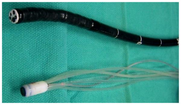
The Hydrojet next to a standard gastroscope (Olympus Corp., Model: GIF180).
Acknowledgment
The authors would like to kindly acknowledge Phil Williams, Director of the Division of Surgical Research at Vanderbilt University Medical Center (VUMC), and the staff at the VUMC S.R. Light Surgical Facilities for Animal Trials for their time and assistance during the in vivo experiment.
Research reported in this publication was supported in part by the Vanderbilt Initiative in Surgery and Engineering, in part by the National Institute of Biomedical Imaging And Bioengineering of the National Institutes of Health under Award Number R01EB018992, and in part by the National Science Foundation under grant number CNS-1239355. Any opinions, findings and conclusions or recommendations expressed in this material are those of the authors and do not necessarily reflect the views of the NIH or the NSF.
Biographies

Robert Caprara (S’14) received B.S. (cum laude) and M.Eng. (summa cum laude) degrees in Mechanical Engineering from the University of Louisville, Louisville, KY, USA, in 2010 and 2011 respectively. In 2012, he began his PhD studies in Mechanical Engineering at Vanderbilt University, Nashville, TN, USA. Since 2013, he has been a member of the Science and Technology Of Robotics in Medicine (STORM) Laboratory where he has been primarily involved with the development of robotic capsule endoscopy platforms. He was awarded the Vanderbilt Initiative in Surgery and Engineering Fellowship in the Fall of 2014.

Keith L. Obstein is an Assistant Professor of Medicine and an Assistant Professor of Mechanical Engineering at Vanderbilt University. He is also the Associate Program Director of the Gastroenterology Fellowship program at Vanderbilt. Dr. Obstein is the Clinical Director of the STORM Lab at Vanderbilt University and conducts research in the areas of Robotic Endoscopy, New Technologies, Device Development, Endoscopic Training, Capsule Endoscopy, and Healthcare Quality Improvement.

Gabriel Scozzarro is a M.S. student in Medical Engineering at University of Rome Tor Vergata. He spent 2 years collaborating with the University of Rome Tor Vergata Medical Center as a research intern. Since 2011, he has been a visiting student with the STORM Lab at Vanderbilt University. He is actively involved in the design of capsule robots for hydro-colonoscopy and research in magnetic coupling actuation.
Christian Di Natali (S’10) received B.S. and M.S. degrees (Hons.) in Biomedical Engineering from the University of Pisa, in 2008 and 2010. In 2011, he joined the Institute of BioRobotics of Scuola Superiore Sant’Anna, as a research assistant working on magnetic coupling and teleoperated magnetic navigation. In the Fall 2011, he started the PhD program in Mechanical Engineering at Vanderbilt University. He is a member of the STORM lab, and he is actively involved in the design of advanced magnetic coupling for surgery and endoscopy.

Marco Beccani (S’11) received a Master’s degree in Electronic Engineering from the University of Pisa, Pisa, Italy, in 2010. After spending one year as Research Assistant at the Institute of BioRobotics of Scuola Superiore Sant’Anna, since 2011 he is a PhD student in Mechanical Engineering at Vanderbilt University. He is a member of the STORM Lab, and his field of research is miniaturized realtime embedded system design for wireless robotic capsular endoscopy and robotic surgery.

Douglas R. Morgan is an Associate Professor of Medicine at Vanderbilt University Medical Center. His research and clinical interests are centered on gastric cancer epidemiology, prevention, and clinical translational initiatives in Central America and in U.S. Hispanic populations. Active research collaborations are located in Honduras, Nicaragua, and El Salvador. Additional discipline areas include novel endoscopy and imaging technologies.

Pietro Valdastri (M’05, SM’13) received a Master’s (Hons.) degree in Electronic Engineering from the University of Pisa, Pisa, Italy, in 2002, and a Ph.D. degree in Biomedical Engineering from Scuola Superiore Sant’Anna (SSSA), Pisa, Italy. After spending three years as Assistant Professor at the Institute of BioRobotics of SSSA, since 2011 he is Assistant Professor at the Department of Mechanical Engineering at Vanderbilt University, where he founded the STORM Lab. He is actively involved in robotic endoscopy and robotic surgery, design of magnetic mechanisms, and design of capsule robots for medical applications.
References
- [1].Ferlay J, et al. Globocan 2012, cancer incidence and mortality world-wide: IARC CancerBase. 2013.
- [2].American Cancer Society Cancer facts & figures 2005. 2005.
- [3].Bray F, et al. Global cancer transitions according to the human development index: a population-based study. The Lancet Oncology. 2012;13:790–801. doi: 10.1016/S1470-2045(12)70211-5. [DOI] [PubMed] [Google Scholar]
- [4].Adami H-O, et al. Primary and secondary prevention in the reduction of cancer morbidity and mortality. Eur. J. Cancer. 2001;37(Suppl 8):S118–S127. doi: 10.1016/s0959-8049(01)00262-3. [DOI] [PubMed] [Google Scholar]
- [5].Lee K-J, et al. Gastric cancer screening and subsequent risk of gastric cancer: a large-scale population-based cohort study, with a 13-year follow-up in Japan. Int. J. Cancer. 2006 May;118(9):2315–21. doi: 10.1002/ijc.21664. [DOI] [PubMed] [Google Scholar]
- [6].Makuuchi H, et al. Endoscopic screening for esophageal cancer in 788 patients with head and neck cancers. The Tokai Journal of Experimental and Clinical Medicine. 1996;21:139–145. [PubMed] [Google Scholar]
- [7].Oshima A, et al. Evaluation of a mass screening program for stomach cancer with a case-control study design. Int. J. Cancer. 1986 Dec;38(6):829–33. doi: 10.1002/ijc.2910380608. [DOI] [PubMed] [Google Scholar]
- [8].Wilhelm TJ, et al. Gastrointestinal endoscopy in a low budget context: delegating EGD to non-physician clinicians in Malawi can be feasible and safe. Endoscopy. 2012 Feb;44(2):174–6. doi: 10.1055/s-0031-1291446. [DOI] [PubMed] [Google Scholar]
- [9].Koulaouzidis A, Douglas S. Capsule endoscopy in clinical practice: concise up-to-date overview. Clinical and Experimental Gastroenterology. 2009 Jan;2:111–6. doi: 10.2147/ceg.s4758. [DOI] [PMC free article] [PubMed] [Google Scholar]
- [10].Rey JF, et al. Feasibility of stomach exploration with a guided capsule endoscope. Endoscopy. 2010 Jul;42(7):541–5. doi: 10.1055/s-0030-1255521. [DOI] [PubMed] [Google Scholar]
- [11].Mishkin DS, et al. ASGE technology status evaluation report: wireless capsule endoscopy. Gastrointestinal Endoscopy. 2006 Apr;63(4):539–45. doi: 10.1016/j.gie.2006.01.014. [DOI] [PubMed] [Google Scholar]
- [12].Keller H, et al. Method for navigation and control of a magnetically guided capsule endoscope in the human stomach. Proc. of the IEEE RAS and EMBS Int. Conf. on Biomedical Robotics and Biomechatronics. 2012:859–865. [Google Scholar]
- [13].Yim S, Sitti M. Design and analysis of a magnetically actuated and compliant capsule endoscopic robot. 2011 IEEE Int. Conf. Robot. Autom. 2011 May;:4810–4815. [Google Scholar]
- [14].Yim S, et al. Magnetically actuated soft capsule with the multimodal drug release function. IEEE/ASME Trans. Mechatronics. 2013;18(4):1413–1418. doi: 10.1109/TMECH.2012.2235077. [DOI] [PMC free article] [PubMed] [Google Scholar]
- [15].Yim S, et al. Biopsy using a magnetic capsule endoscope carrying, releasing, and retrieving untethered microgrippers. IEEE Trans. Biomed. Eng. 2014 Feb;61(2):513–21. doi: 10.1109/TBME.2013.2283369. [DOI] [PMC free article] [PubMed] [Google Scholar]
- [16].Tortora G, et al. Propeller-based wireless device for active capsular endoscopy in the gastric district. Minimally Invasive Therapy & Allied Technologies. 2009;18:280–290. doi: 10.1080/13645700903201167. [DOI] [PubMed] [Google Scholar]
- [17].De Falco I, et al. An integrated system for wireless capsule endoscopy in a liquid-distended stomach. IEEE Trans. Biomed. Eng. 2013 Mar;61(3):794–804. doi: 10.1109/TBME.2013.2290018. [DOI] [PubMed] [Google Scholar]
- [18].Shaker R, et al. Principles of Deglutition. Springer Science & Business Media; 2012. [Google Scholar]
- [19].Varadarajulu S, et al. GI endoscopes. Gastrointestinal Endoscopy. 2011 Jul;74(1):1–6.e6. doi: 10.1016/j.gie.2011.01.061. [DOI] [PubMed] [Google Scholar]
- [20].Hall JE. Guyton and Hall Textbook of Medical Physiology. 2010.
- [21].Clark RK. Anatomy and Physiology: Understanding the Human Body. Jones and Bartlett; Sudbury, MA: 2005. [Google Scholar]
- [22].Mayo Clinic Health System EGD - Mayo Clinic Health System. 2013 [Online]. Available: http://mayoclinichealthsystem.org/locations/ eau-claire/medical-services/gastroenterology-and-hepatology/egd.
- [23].Moshkowitz M, et al. A novel device for rapid cleaning of poorly prepared colons. Endoscopy. 2010;42:834–836. doi: 10.1055/s-0030-1255777. [DOI] [PubMed] [Google Scholar]
- [24].American Conference of Government Industrial Hygienists Threshold limit values, permissible exposure limits, and feasibility: the bases for exposure limits in the United States. 1996. [DOI] [PubMed]
- [25].Valdastri P, et al. Advanced technologies for gastrointestinal endoscopy. Annu. Review of Biomed. Eng. 2012;14:397–429. doi: 10.1146/annurev-bioeng-071811-150006. [DOI] [PubMed] [Google Scholar]
- [26].Ascari L, et al. A new active microendoscope for exploring the subarachnoid space in the spinal cord. 2003 IEEE Int. Conf. Robot. Autom. 2003;2:2657–2667. [Google Scholar]
- [27].Howell LL. Compliant Mechanisms. John Wiley and Sons; New York, NY: 2001. [Google Scholar]
- [28].Xu K, Simaan N. Analytic formulation for kinematics, statics, and shape restoration of multibackbone continuum robots via elliptic integrals. Journal of Mechanisms and Robotics. 2010;2 [Google Scholar]
- [29].Kravitz S. Packing cylinders into cylindrical containers. Mathematics Magazine. 1967;40(2):65–71. [Google Scholar]
- [30].Ferro A, et al. Worldwide trends in gastric cancer mortality (1980-2011), with predictions to 2015, and incidence by subtype. Eur. J. Cancer. 2014 May;50(7):1330–44. doi: 10.1016/j.ejca.2014.01.029. [DOI] [PubMed] [Google Scholar]


