

Abstract
Insects exhibit an elaborate repertoire of behaviors in response to environmental stimuli. The central complex plays a key role in combining various modalities of sensory information with an insect's internal state and past experience to select appropriate responses. Progress has been made in understanding the broad spectrum of outputs from the central complex neuropils and circuits involved in numerous behaviors. Many resident neurons have also been identified. However, the specific roles of these intricate structures and the functional connections between them remain largely obscure. Significant gains rely on obtaining a comprehensive catalog of the neurons and associated GAL4 lines that arborize within these brain regions, and on mapping neuronal pathways connecting these structures. To this end, small populations of neurons in the Drosophila melanogaster central complex were stochastically labeled using the multicolor flip-out technique and a catalog was created of the neurons, their morphologies, trajectories, relative arrangements, and corresponding GAL4 lines. This report focuses on one structure of the central complex, the protocerebral bridge, and identifies just 17 morphologically distinct cell types that arborize in this structure. This work also provides new insights into the anatomical structure of the four components of the central complex and its accessory neuropils. Most strikingly, we found that the protocerebral bridge contains 18 glomeruli, not 16, as previously believed. Revised wiring diagrams that take into account this updated architectural design are presented. This updated map of the Drosophila central complex will facilitate a deeper behavioral and physiological dissection of this sophisticated set of structures. J. Comp. Neurol. 523:997–1037, 2015. © 2014 Wiley Periodicals, Inc.
Keywords: Drosophila brain, glomerulus, ellipsoid body, fan-shaped body, nodulus, MCFO, AB_1549585, AB_1625981, AB_915420, AB_528108
The Drosophila central complex comprises a set of four neuropils that straddle the midline of the protocerebrum in the center of the brain. In each of these four neuropils, an intricate collection of neurons is exquisitely assembled and precisely connected to neighboring neuropils to conduct the many complex behaviors of the fly. The central complex serves as an integration center for diverse motor, sensory, learning, and memory activities in insects. It is involved in coordinating locomotor behavior, including flight and various aspects of walking in flies and cockroaches (Bausenwein et al., 1986; Strauss and Heisenberg, 1993; Ilius et al., 1994; Martin et al., 1999; Ridgel et al., 2007; Bender et al., 2010); visual stripe fixation as well as the initiation, organization, and integration of behavior (Bausenwein et al., 1994); visual feature processing (Seelig and Jayaraman, 2013); sensory-guided changes in orientation and locomotion in the cockroach (Bender et al., 2010; Guo and Ritzmann, 2013); various types of memory in flies (Liu et al., 2006; Neuser et al., 2008; Pan et al., 2009; Ofstad et al., 2011; Kuntz et al., 2012); angular reach in gap crossing (Triphan et al., 2010); sleep (Donlea et al., 2011; Donlea et al., 2014); sound production during courtship (Popov et al., 2003); gravitaxis (Baker et al., 2007); and in sun-compass navigation in the locust and monarch butterfly (Heinze and Homberg, 2007; Heinze and Reppert, 2011).
The central complex is highly conserved across insect species, and while the degree of functional conservation remains largely unknown, structural conservation is strong, although there are conspicuous differences in the basic blueprint of this brain region. All insects examined to date have a protocerebral bridge (PB), a caudal neuropil that resembles mustache handlebars in shape (Fig. 1). The PB is vertically divided into distinct units called glomeruli (G). The noduli (NO) lie rostral to the PB and constitute the only paired neuropil of the central complex structures (Fig. 1). Depending on the species, anywhere from two to four discrete units precariously stacked on top of one another on each side of the midline constitute the noduli. While the stacked noduli have been referred to as (horizontal) layers, no vertical divisions have been reported for these structures. The anteriormost structure is the central body (CB), which, in some insects, comprises an upper (CBU) and lower (CBL) half. In Diptera, the structures homologous to the CBU and CBL are called the fan-shaped body (FB) and ellipsoid body (EB), respectively (Fig. 1). The FB is posterior to the EB and is the largest of the central complex neuropils. It is subdivided vertically into columns, known as segments in Drosophila (Hanesch et al., 1989) and staves in Musca (Strausfeld, 1976). Along the anterior–posterior axis of the FB, Hanesch et al. (1989) observed four shells, delineated by the positions and extent to which arbors from small-field neurons project into these FB domains. The most prominent subdivisions of the FB are the horizontal layers, evident in brains immunolabeled to reveal the density of synapses (Fig. 1F). The ventral half of the EB is the most anterior neuropil of the central complex; the EB is partially embedded in the FB and is tilted on its axis such that the dorsal half is oriented more posteriorly. In Drosophila, the EB is shaped like a torus, whereas in other Diptera, as well as most other insects, its shape more closely resembles that of a kidney bean (Strausfeld, 1976). Similar to the FB, the EB is subdivided on three axes but the EB terminology is inconsistent with that used for equivalent axes in the FB. Divisions along the anterior–posterior axis (shells in the FB) are called rings in the EB (Hanesch et al., 1989). Concentric rings along the radius of the EB are called layers (Young and Armstrong, 2010b), deriving their name from the homologous and more obvious "layers" in the noncircular CBL and the more common arched or kidney-bean form of the EB in other, non-Drosophila dipterans. Finally, the vertical divisions analogous to the PB glomeruli are the wedge-shaped divisions along the radius of the toroid that resemble pieces of pie. The analogy to the PB glomeruli is evident if the torus is split at its base and the formerly joined ends stretched away from one another, thereby converting rings into layers. These divisions are called sectors or segments (Hanesch et al., 1989).
Figure 1.

Central complex. A: The central complex straddles the midline in the central brain (gray). Its four components are the protocerebral bridge (solid purple fill; posterior), fan-shaped body (green), ellipsoid body (orange; anterior); and noduli (solid blue fill). Accessory neuropils that are arborized by PB neurons include the crepine (CRE, transparent blue), rubus (RUB, yellow), gall (GA, red), and lateral accessory lobe (LAL, transparent purple). Posterior (B), sagittal (C; anterior to the right), and dorsal (D) views of the central complex. Images A–D were generated using Fluorender (Wan et al., ,). The four components of the central complex are shown immunolabeled with anti-nc82: (E) PB, (F) FB, (G) EB, and (H) NO. Asterisks in F highlight the layers that can be distinguished by differences in synaptic density, as measured by intensity of nc82 signal. Dorsal is up. Scale bars = 20 μm in A–D; 10 μm in E–G; 11 μm in H.
Central complex structures communicate extensively with numerous associated regions in the central brain. Historically, the lateral accessory lobes (LAL; Fig. 1; also known as the ventral bodies) and the bulb (BU, commonly referred to as the lateral triangle) have been recognized as prominent association areas, although additional regions, such as the gall (GA; Fig. 1), also constitute key centers of communication.
Coherent and in-depth functional studies on the central complex and its associated regions require both a detailed and comprehensive anatomical map of the constituent neurons of the central complex and its neighboring accessory neuropils as well as a set of GAL4 lines that targets these neurons. This map will need to 1) provide a detailed description of the architectural framework in which these neurons reside, 2) define inputs and outputs to each of the substructures that integrates sensory input with behavioral output, and 3) illustrate the connections between these brain regions. The work presented here contributes to the generation of this map by refining the architecture of a subset of neuropils of the central brain, including the four components of the central complex and some associated regions, and by illustrating the "wiring rules" used by neurons to connect these substructures of the central complex. The neurons described in this work focus almost exclusively on cells that arborize in the PB. We expect that most PB cell types are reported here, although electron microscope (EM) reconstruction will be required to verify complete coverage. At least two cells are known to be excluded from this description: one cell type identified by Lin et al. (2013) that was not seen in this study, and one cell seen only twice in this study, and neither time in its entirety. When necessary, cells that do not arborize in the PB are included in the analysis both to provide a more comprehensive description of the anatomy of central complex structures and to strengthen connectivity and architectural claims suggested by PB neurons.
We present revised circuitry "rules" and anatomical maps of the four central complex regions and neuropils associated with the central complex. We also provide an atlas of the PB cells identified in this study and corresponding Drosophila GAL4 lines that identify these cells. These data provide a template for a full reconstruction of the protocerebral bridge neurons at an EM level. The tools and reagents will also enable and facilitate a broad range of behavioral and physiological studies into the neural basis of spatial navigation, visual learning, and other complex behaviors involving the central complex.
Materials and Methods
Multicolor flip-out technique and reagents
Approximately 35 GAL4 lines were selected from a collection of 7,000 GAL4 lines (Jenett et al., 2012) based on their expression patterns in the central complex. These lines were characterized using the multicolor flip-out (MCFO) technique (Nern et al., in prep.), which generates stochastically labeled single cells in a spectrum of colors. This method employs a transcription unit and a transcriptional stop signal. The ability of the transcription unit to produce a product is blocked by a transcriptional stop signal. The stop signal can be removed by the action of a site-specific recombinase, and the fraction of cells in which the stop signal is removed—and thus the density of immunolabeling—can be varied by adjusting the level of recombinase produced (Struhl and Basler, 1993). Briefly, UAS reporter constructs carrying Flag, VK5, and HA epitope tags (pJFRC206-5xUAS-IVS-myr::smGFP-FLAG in VK00005 and pJFRC200-10xUAS-IVS-myr::smGFP-HA in attP18, Viswanathan et al., submitted) downstream of an FRT-flanked stop signal were excised by limited expression of FLP recombinase activity. The following Flp stocks were used.
57C10-FlpPEST->su(Hw)attP8:HA_V5_FLAG_1; 57C10-wtFlp->su(Hw)attP8:HA_V5_FLAG_1; 57C10-FlpL->attP18:HA_V5_FLAG_1;57C10-FlpLwt->su(Hw)attP8:HA_V5_FLAG_1. GAL4 stocks are noted throughout the text. Flies were dissected anywhere from eclosion to 2 weeks to achieve the desired density of labeled cells. Tissue was subsequently labeled with epitope tag-specific antibodies. With one exception, exclusively female brains were analyzed in this study. In all, 17 of the known 18 cell types were identified within the set of ∼35 GAL4 lines.
Immunohistochemistry
For a complete list of antibodies used in this study, refer to Table1. Immunohistochemistry and mounting were performed according to the protocol developed by Nern et al. (in prep.). Brains were dissected in Schneider's medium and fixed in 2% paraformaldehyde (PFA) in Schneider's medium for 50 minutes at room temperature (RT, 22°C). Samples were then rinsed 4 × 10 minutes at RT in PAT3 (0.5% Triton X-100/0.5% bovine serum albumin [BSA] in phosphate-buffered saline [PBS]), followed with a blocking step in 3% normal goat serum (NGS) in PAT3 for 90 minutes at RT. Next, tissue was incubated in mouse anti-nc82, an antibody against Bruchpilot (1:30; Developmental Studies Hybridoma Bank, University of Iowa; RRID: AB_528108; Wagh et al., 2006; Hofbauer et al., 2009), rabbit anti-HA (1:300; Cell Signaling Technology, Beverly, MA; RRID: AB_1549585), and rat anti-Flag (1:200; Novus Biologicals, Littleton, CO; RRID:AB_1625981) in 3% NGS/PAT3 for 4 hours at RT, then overnight at 4°C. Tissue was brought to RT and washed 3 × 30 minutes at RT. Samples were then incubated in Alexafluor-488 donkey antimouse (1:400; Jackson ImmunoResearch Laboratories, West Grove, PA), Alexafluor-594 donkey antirabbit (1:500; Jackson Labs), and Alexafluor-647 donkey antirat (1:300; Jackson Labs) in 3% NGS/PAT3 for 4–6 hours at RT and 3–5 days at 4°C. Tissue was brought to RT and rinsed 3 × 30 minutes in PAT3. Brains were then blocked in 5% normal mouse serum/PAT3 for 1 hour at RT, then incubated in DyLight-549 mouse anti-V5 (1:500; AbD Serotec; AB_915420) for 4–6 hours at RT, then overnight at 4°C. Following 3 × 30 minutes washes in PAT3 at RT and one 15-minute wash in PBS, tissue was fixed in 4% PFA in PBS at RT for 4 hours, then rinsed once for 15 minutes at RT in PBS. Finally, tissue was rinsed 5× in PAT3 at RT for 10–15 minutes per wash. Tissue was mounted within 3–5 days of final PAT3 washes. If tissue was mounted after more than 2 days, it was first washed once more in PAT3.
Table 1.
Primary Antibodies Used in This Study
| Antibody | Immunogen | Source | Dilution |
|---|---|---|---|
| Anti-Bruchpilot | Amino acids 1105–1740 of Drosophila Bruchpilot C-terminus | DSHB, mouse, monoclonal, nc82, RRID: AB_528108 | 1:30 |
| Anti-HA | Influenza HA epitope YPYDVPDYA | Cell Signaling Technology, 3724S, rabbit, monoclonal, RRID: AB_1549585 | 1:300 |
| Anti-FLAG | N-terminal DYKDDDDK-tagged ECD of mouse Langerin | Novus Biologicals, NBP1–06712, rat, monoclonal, RRID:AB_1625981 | 1:200 |
| Anti-V5 | Paramyxovirus SV5 | AbD Serotec, MCA 1360D549, mouse, monoclonal, RRID: AB_915420 | 1:500 |
Antibody characterization
The specificity of nc82 against BRP protein has been demonstrated by: 1) the expression pattern of GFP-tagged bruchpilot driven under tissue-specific drivers, which matches nc82 signals in wing discs and tracheal cells, and is also targeted to the active zone of larval NMJ boutons (Wagh et al., 2006); 2) western blots of adult head extracts using nc82 (Wagh et al., 2006); and 3) the loss of immune-expression in brp mutant neuromuscular junctions and rescue by expression of BRP in brp mutants (Kittel et al., 2006). nc82 has been widely used to label synaptic sites in Drosophila, based largely on the pattern of labeling demonstrated at neuromuscular junctions and fly photoreceptor synapses (Hamanaka and Meinertzhagen, 2010), but reports of its specificity are mostly not complete for synapses of the CNS. In particular, nc82 labels the platform of the T-bar ribbon, and not only has nc82 not been shown to label the platforms at CNS synapses, but not all synapses in the CNS have such organelles (Butcher et al., 2012).
The specificities of the three epitope-tagged antibodies, rat anti-FLAG, rabbit anti-hemagglutinin (anti-HA), and mouse anti-V5, are validated by the internal controls of the flip-out approach in that: 1) expression patterns differ by GAL4 line and 2) the extent of labeling varies from no label to dense label even though the GAL4 drivers are reasonably broad.
Clearing and mounting
Tissue was dehydrated through an ethanol series, 10 minutes each in 30%, 50%, 75%, and 95% EtOH and then placed on poly L-lysine-coated coverslips (No. 1) while immersed in 95% EtOH. Once mounted, samples were dehydrated 3 × 10 minutes in 100% EtOH in Coplin jars, and then 3 × 5 minutes in 100% xylene. Spacers (No. 2) were placed on the microscope slide, DPX (Sigma-Aldrich, St. Louis, MO) added to the coverslip-mounted tissue, and the coverslip placed on the spacers, tissue side down. Samples were dried for 2 days at RT before imaging.
Image acquisition
Brains were imaged using a Zeiss LSM 780 confocal microscope and a Plan-Apochromat 63×/1.4 oil immersion objective. Images were scanned at a frame size of 1024 × 1024 pixels, voxel size = 0.19 × 0.19 × 0.38 μm, zoom 0.8 and one frame average.
Image analysis
Confocal stacks were viewed and analyzed using the Janelia Workstation, image-viewing software being developed at Janelia Research Campus (Murphy et al., 2014). The suite of tools available in the Workstation enables confocal stacks to be viewed in both two and three dimensions and to be annotated with a user-generated ontology. The Workstation provides an efficient, intuitive, and customized alternative to publicly available platforms such as FIJI.
Neuropil masks
Neuropil masks were generated using Fluorender, nc82-labeled brains obtained in this work, and a standard brain (JFRC2013). Details of methodology are available in Aso et al. (eLife, in press).
Figure preparation
Brightness and contrast were adjusted in the Janelia Workstation for improved visualization of neurons. Adobe Photoshop (San Jose, CA) was occasionally used to hide nc82 immunolabeling or primary neurites of nonessential cells if they interfered with visualizing the relevant neurons in a figure.
Results
New naming convention
Naming conventions for neurons in the central complex range from being too broad and ambiguous to accommodate the level of detail essential for the studies reported here to being too esoteric for one not well acquainted with the field. In an effort to simplify a compartment-rich structure with many regions, domains, and subdomains, we use a new convention that provides an intuitive description of each cell type discussed.
In the nomenclature system used here, neurons are named based on their axonal paths—the domains in which they arborize—and, when possible, the predominant polarity of their arbors at each synaptic junction. Several examples of neuron names and accompanying tutorials on how to translate the names are provided in Figure 2 (see legend for details) and abbreviations for the terms in the names are presented in Table2.
Figure 2.

Nomenclature design. A: This generic schematic illustrates the nomenclature system. Three neuropils are shown. Neuropil 1, the first neuropil in a neuron's "name," is the neuropil closest to the cell body. The subdomains (abbreviated sd in the figure) are included in the neuron's name to define the subregion/s of the neuropils in which the cell type arborizes. For example, there are several distinct volumes in the EB, so the volume that is specific to a given cell type is included in the name. The third component of a cell's name is the predominant morphology of its arbors, abbreviated as either "s" for spines, or "b" for boutons. B,C: Two neurons are shown, accompanied by schematics to illustrate the cells' locations in the central complex, and by the neuron's name, annotated to illustrate how the name is derived. Letters that are used in the neuron names are highlighted in color. Ovals in the schematics represent the cell bodies, solid and hatched fills denote spine and bouton arbor morphologies, respectively. PB: protocerebral bridge; GA: gall; EB: ellipsoid body; cb: cell body; s: spines; b: boutons; FB: fan-shaped body; RUB: rubus.
Table 2.
Abbreviations
| PB | protocerebral bridge |
| FB | fan-shaped body |
| EB | ellipsoid body |
| NUB | nubbin |
| NO1 | nodulus 1, dorsal nodulus |
| NO2 | nodulus 2, medial nodulus |
| NO3 | nodulus 3, ventral nodulus |
| NO2D | dorsal compartment of NO2 |
| NO2V | ventral compartment of NO2 |
| NO3P | posterior compartment of NO3 |
| NO3M | medial compartment of NO3 |
| NO3A | anterior compartment of NO3 |
| LAL | lateral accessory lobe |
| GA | gall |
| GA-t | gall tip |
| GA-s | gall surround |
| CRE | crepine |
| RUB | rubus |
| PS | posterior slope |
| SPS | superior posterior slope |
| IB | inferior bridge |
| G | glomerulus of PB |
| G# | subset of glomeruli designated by number/s |
| ℓ | layer (of FB) |
| EBw | wedge (EB domain) |
| EBt | tile (EB domain) |
| s | spines/spiny |
| b | boutons |
| D | dorsal |
| V | ventral |
| P | posterior |
| i | ipsilateral |
| c | contralateral |
This naming scheme provides a naive reader with sufficient information both to correlate a cell with its name and to deduce with reasonable accuracy its morphology, since the connectivity path and the morphological features of arbors at each synaptic junction are unique for each cell type. Such a system also obviates the need for a historical knowledge of neuron nomenclature (for example, a "P1" neuron). While some important morphological details are not included in the path, such as size and location of the soma and trajectory of the primary neurite, inclusion of all details would be inordinately cumbersome and unlikely to be essential to distinguish unique cell types. Established nomenclature, as described in Ito et al. (2014), is used when possible and when it was considered accurate and sufficient in light of the new findings described here. Newly identified compartments are named in accordance with preexisting terms, when possible. (For example, two, not one, regions constitute the medial nodulus, or NO2, and are referred to here as the dorsal and ventral compartments of NO2.) When necessary, "ipsilateral" ("i") and "contralateral" ("c") are included in the neuron's name; these designations are context-dependent. For example, in complex arborization patterns these designations provide geographic information about the locations of the arbors. In cases in which the neuron does not arborize in the PB, the cell body serves as the reference point, as follows: If the arbor is on the same side as the cell body, it is considered ipsilateral. Finally, this naming scheme has the added advantage that additional detail can be incorporated as necessary or as it becomes available. For example, during the course of this study it became evident that neurons arborize in only a subset of the glomeruli of the PB, so the designation "Gx-y" was incorporated to identify the specific glomeruli targeted by the cell type, where "x" refers to the number of the medial glomerulus and "y" refers to the lateral glomerulus.
Information about the morphology of the neurites that constitute each arbor is indicated in the cell type's name. These designations are based on light-level analysis and are intended to indicate only the more predominant type of terminal since: 1) morphological distinctions at this level are sometimes ambiguous and 2) many neurons are not exclusively pre- or postsynaptic at a given site (I. Meinertzhagen, pers. comm.; Takemura et al., 2008). Even with the use of polarity markers, discriminating between input and output can be difficult (Nicolai et al., 2010). Indeed, it will likely turn out to be the case that many of the terminals in the cells described here are mixed. Ultimately, EM-level analysis will be necessary to definitively resolve the fine details of an arbor's morphology and the polarity of the cells' terminals. In the neuronal path nomenclature presented here, bleb-like or bouton terminals are designated "b" (for boutons), spiny or branch-like arbors are designated "s" (for spiny/spines), and mixed terminals as "s.b." (Fig. 2).
Polarity of neurons' terminals is often inferred from the morphology of their neurites. The terminals consisting of boutons are considered to be presynaptic or output, whereas the spiny terminals and are considered to be postsynaptic, dendritic, or input. The assignments provided here are largely consistent with those shown in Lin et al. (2013).
Note that "left" and "right" are used throughout the text to refer to the left and right halves of the PB. These terms refer not to the fly's left and right, but rather, to the left and right sides of the figure, as seen by the reader. Given the bilateral symmetry of the PB, the distinction serves only as a point of reference to orient the reader to the figures.
Criteria used to define unique cell types
Since there is not a consensus for the definition of cell type, we used the following logic to define a cell type for the studies presented here: We assume that cells of a cohort that follow the same path and have identical morphology survey the environment for the same information and deliver the same information (albeit from different coordinates in the environment) to the same downstream centers. This line of logic suggests these cells perform the same function and consequently should be considered to be members of the same cell type. Therefore, a cell's path was used to define its cell type, so each of the 17 PB cell types identified in this study follows a unique projection (Fig. 3, Table3). Lin et al. (2013) adopted a more conservative definition in which they define cells that are likely performing the same function for different points in space as different cell types (in other words, the same cell performing the same function in different glomeruli).
Figure 3.

Protocerebral bridge neuron catalog. Confocal images of all neurons with arbors in the PB that were identified in this study are shown. Each image is accompanied by a sketch that illustrates the neuropils in which the neuron arborizes. A: This schematic illustrates all neuropils that are arborized by the PB neurons described here, except the inferior bridge (IB) and superior posterior slope (SPS), which were omitted to simplify the schematic. The IB and SPS are shown in Ito et al., 2014. The schematic illustrates the current understanding of the subvolumes that constitute each of the neuropils shown, which is derived from work presented here. The neuropils were traced from a single focal plane of nc82-immunolabeled specimens, so they reflect the approximate shapes of their respective brain regions. The layout and relative sizes of the neuropils were modified to accommodate the two dimensionality of the schematic. The color scheme was chosen to best separate adjacent volumes and is not coordinated with volumes of similar color within this schematic, nor with any neurons or figures in the text. PB: protocerebral bridge. Numbers 1–9 in the PB identify each of the glomeruli of this neuropil. FB: fan-shaped body. Layers 1–9 of the FB are indicated. The relative widths of each layer are accurate for the focal plane shown. The irregular line that demarcates layer 4 from layer 5 is intended to illustrate the gaps in nc82 label in this region. The serrated ventral boundary of layer 1 depicts the seven teeth of this layer, as described below. The gall comprises three regions: the gall tip (GT), dorsal gall (DG), and ventral gall (VG). LAL: lateral accessory lobe. EB: ellipsoid body. CRE: crepine. RUB: rubus. NO1: dorsal nodulus. NO2D: dorsal subcompartment of medial nodulus. NO2V: ventral subcompartment of medial nodulus. NO3: ventral nodulus; individual subcompartments of this neuropil are not indicated in the schematic. B–U: Confocal images and sketches of neurons drawn on the template shown in A. Neuropils that are arborized by the neurons are highlighted in black, whereas regions that are not populated by a given neuron are shadowed in gray. In the sketches, spiny arbors are drawn as random scribbles and boutons are illustrated as dots. B: PBG2–9.s-FBℓ1.b-NO3P.b. C: PBG2–9.s-FBℓ1.b-NO3M.b. D: PBG2–9.s-FBℓ2.b-NO3A.b. E: PBG2–9.s-FBℓ3.b-NO2D.b. To more accurately depict the morphology of the arbor in layer 3 of the FB, it is shown extending into layer 4 in the drawing although in reality, the arbor is confined to layer 3. F: PBG2–9.s-FBℓ3.b-NO2V.b. The sense of depth conveyed by the maximum intensity projection of the confocal image is not conveyed in the 2-dimensional drawing. Consequently, the morphology of the NO2V arbor appears different in the sketch compared to the confocal image. G: PBG2–9.s-EBt.b-NO1.b.
Table 3a.
Comparison of Cell Types I
| Wolff et al. cell name | Lin et al. cell name | Wolff et al. features | Lin et al. features | |
|---|---|---|---|---|
| 1 | PBG2–9.s-FBℓ1.b-NO3P.b | PB1-glomerulus->FBf-NoL4 | does not arborize in G1 | arborizes in all glomeruli |
| arborizes in subcompartment of NO3 | arborizes in separate nodulus: NO4 | |||
| 2 | PBG2–9.s-FBℓ1.b-NO3M.b | NI | does not arborize in G1 | |
| 3 | PBG2–9.s-FBℓ2.b-NO3A.b | PB1-glomerulus->FBe-NoL3 | does not arborize in G1 | arborizes in all glomeruli |
| 4 | PBG2–9.s-FBℓ3.b-NO2D.b | PB1-glomerulus->FBd-NoL2 | does not arborize in G1 | arborizes in all glomeruli |
| 5 | PBG2–9.s-FBℓ3.b-NO2V.b | NI | does not arborize in G1 | |
| 6 | PBG2–9.s-EBt.b-NO1.b | PB1-glomerulus->EBP-NoR1 | does not arborize in G1 | arborizes in all glomeruli |
| 7 | PBG1–8.s-EBt.b-D/Vgall.b | PB1-glomerulus->EBC-IDFPDSB | does not arborize in G9 | arborizes in all glomeruli |
| odd G to D gall; even G to V gall | all glomeruli to D gall | |||
| glomerular tendrils respect "odd/even rule" | ||||
| 8 | PBG1–8.b-EBw.s-D/Vgall.b | EBC,O,P->EBC,O,P-IDFPD/VSB-PB1-glomerulus | does not arborize in G9 | arborizes in all glomeruli |
| considered same cell type as | ||||
| EBC,P->EBC,P-IDFPDSB-PB1-glomerulus | ||||
| odd G to D gall; even G to V gall | G1 to D or V gall; G3,5,7 to V gall; G2,4,6,8 to D gall | |||
| 1:1 PB:EB correspondence glomerular tendrils respect "odd/even rule" | 3:1 PB:EB and 1:5 PB:EB correspondence | |||
| evidence for mixed terminals | mixed spiny and bouton terminals | |||
| is ambiguous | ||||
| 9 | PBG9.s-EB.P.s-ga-t.b | EBC,P->EBC,P-IDFPDSB-PB1-glomerulus | arborizes only in G9 | considered same cell type as EBC,O,P->EBC,O,P-IDFPD/VSB-PB1-glomerulus |
| EB arbor is sparse but fills entire wedge | EB arbor fills half a wedge | |||
| arborizes in gall tip | arborizes in dorsal gall | |||
| 10 | PB.s-FBℓ6.b.ℓ3.s-Vga-s.b | PB1-glomerulus-FBb,d-IDFPDSB | ||
| 11 | PBG1–8.s-FBℓ3,4,5.s.b-rub.b | PB1-glomerulus-FBc,d->IDFPRB | G1 arbor projects ipsilaterally | G1 arbor projects either ipsilaterally or contralaterally |
| arborizes in 3 FB layers | arborizes in 2 FB layers | |||
| 12 | PBG1–7.s-FBℓ2.s-LAL.b-cre.b | PB1-glomerulus-FBe->IDFPHB-lateral | does not arborize in 2 most lateral glomeruli | does not arborize in single most lateral glomerulus |
| 13 | PB.b-LAL.s-PS.s | CVLPmedial-IDFPHB-lateral-VMPlateral->PB16-glomeruli | ||
| 14 | PBG6–8.sG9.b | PB6-glomeruli | ||
| 15a | PB18.s-GxΔ7Gy.b | PB15-glomeruli | same cell type as PB18.s-9i1i8c.b | different cell type from PB16-glomeruli |
| spiny arbor in all glomeruli | spiny arbor in all but one glomerulus | |||
| bouton arbors spaced 7 glomeruli apart | bouton arbors spaced 5 glomeruli apart | |||
| 15b | PB18.s-9i1i8c.b | PB16-glomeruli | same cell type as PB18.s-GxΔ7Gy.b | different cell type from PB15-glomeruli |
| presynaptic arbors spaced 7 glomeruli apart | presynaptic arbors spaced 6 glomeruli apart | |||
| 16 | PBG1/2–9.b-SPSi.s | NI | ||
| 17 | PBG2–9.b-IB.s.SPS.s | CCPventral-VMPdorsal->PB2-glomeruli | arborizes in 1 to several G, not | arborizes in 2 adjacent glomeruli |
| necessarily adjacent does not arborize in G1 | ||||
| 18 | NI | PB1-glomerulus-FBc,d,e,f->IDFPHB-medial | ||
| 17 cell types | 14 cell types | |||
| Net total: 18 PB cell types | ||||
| NI: not identified in this study | ||||
Multicolor flip-out technique as a tool for refined anatomical studies
The multicolor flip-out (MCFO) technique provides an opportunity to visualize neurons at high resolution, both singly and in small populations. This technique makes it possible to label neighboring cells in a spectrum of unique colors, providing a degree of precise spatial information not accessible with techniques used previously. In addition, a much larger number of individual cells for analysis can be generated when using the MCFO technique. This larger and more spatially refined dataset of the relative positions of uniquely colored cells revealed new insights into the architecture and circuitry of the Drosophila central complex, as well as new cell types. Most of the cell types described here were not identified in Hanesch et al. (1989; Table4) but were identified in Lin et al. (2013), although there are notable differences between the Lin et al. and this account, which are presented in Table3. A summary of cell types and GAL4 lines that identify them are presented in Table5. The revised anatomical framework of the central complex and associated structures are presented first followed by the neuronal circuits between these structures.
Table 3B.
Comparison of Cell Types II
| Hanesch et al. (1989) | Wolff et al. | |
|---|---|---|
| 1 | pb-fb-no | PBG2–9.s-FBℓ1.b-NO3P.b |
| PBG2–9.s-FBℓ1.b-NO3M.b | ||
| PBG2–9.s-FBℓ2.b-NO3A.b | ||
| PBG2–9.s-FBℓ3.b-NO2D.b | ||
| PBG2–9.s-FBℓ3.b-NO2V.b | ||
| 2 | pb-eb-no | PBG2–9.s-EBt.b-NO1.b |
| 3 | pb-fb-eb | NI |
| 4 | pb-fb/pb-fb-fb | NI |
| 5 | pb-eb/pb-eb-eb | NI |
| 6 | pb-no | NI |
| 7 | pb-fb-vbo | PBG1–8.s-FBℓ3,4,5.s.b-rub.b1 |
| 8 | pb-eb-vbo | PB.b-EBw.s-D/Vgall.b1 |
| 9 | pb-eb-ltr | PB.s-EBt.b-D/Vgall.b1 |
| 10 | PB large field | PB18.s.GxΔ7Gy.b |
NI: not identified in this study. VBO is now called the LAL. LTR is now called the BU.
Likely equivalent to corresponding Hanesch et al. cell type.
Table 4.
Protocerebral Bridge Cell Types
| Neuron Cell Type | GAL4 Line # | Figure | Special features |
|---|---|---|---|
| PBG2–9.s-FBℓ1.b-NO3P.b | R15D05, R20C08, R26C04, R38G07, R44C06, R65B12, R85H06 | 3B, 6, 16 | no G1 |
| PBG2–9.s-FBℓ1.b-NO3M.b | R15E12, R20C08, R65B12, R85H06 | 3C, 16 | no G1 |
| PBG2–9.s-FBℓ2.b-NO3A.b | R16D01, R20C08, R26C04, R37A12, R41H08, R65B12 | 3D, 16 | no G1 |
| PBG2–9.s-FBℓ3.b-NO2D.b | R16D01, R20A08, R38C04, R41G11, R44C06, R65B12, R65D07 | 3E, 16 | no G1 |
| PBG2–9.s-FBℓ3.b-NO2V.b | R13D09, R26C04, R37F06, R38C04, R41G11 | 3F, 16 | no G1 |
| PBG2–9.s-EBt.b-NO1.b | R12D09, R13D05, R33A12, R37F06,R41G11, R41H08, R65B12 | 3G, 4, 8, 11,14 | no G1 |
| PBG1–8.s-EBt.b-D/Vgall.b | R33A12 | 2, 3H, 4, 7, 8, 10,13, 14, 17 | Even glomeruli to ventral gall; odd glomeruli to dorsal gall; no G9 |
| PBG1–8.b-EBw.s-D/Vgall.b | R15C03, R19G02, R26B12, R26C04, R33A12, R60D05 | 3I, 4, 7, 8, 9, 10,13, 15, 17 | Even glomeruli to ventral gall; odd glomeruli to dorsal gall; no G9 |
| PBG9.b-EB.P.s-ga-t.b | R26B12, R27G06, R33A12 | 3J, 13, 18 | G9 only; only PB cell that arborizes in gall tip |
| PB.s-FBℓ6.b.s.ℓ3.s-Vga-s.b | R33A12, R38C04 | 3K | PB arbor very minor |
| PBG1–8.s-FBℓ3,4,5.s.b-rub.b | R27G06, R33A12, R41G11 | 2, 3L, 21, 22 | no G9; G1 cell usually follows ipsilateral projection; G1i arbor resides lateral to G8c arbor in FB |
| PBG1–7.s-FBℓ2.s-LAL.b-cre.b | R11B11, R13D09, R44C06 | 3M, 19 | no G9, no G8; most G1 cells project ipsilaterally; LAL arbor comes in 3 lengths; PB arbors multiglomerular |
| PB.b-LAL.s-PS.s | R51B11 | 3N | |
| PBG6–8.sG9.b | R18G01, R41H08 | 3O, 18 | |
| PB18.s-GxΔ7Gy.b1 | R12E10, R34E11, R38G07, R41H08 | 3P, 18 | dendritic arbor in 18 glomeruli; 2 glomeruli -- separated by 7 glomeruli --have pre-synaptic clusters |
| PB18.s-9i1i8c.b1 | R12E10, R34E11, R33D11, R38G07, R41H08 | 3Q | 3 presynaptic clusters at G9 and G1, both ipsi, and G8 on contralateral side; 7 empty glomeruli between each cluster |
| PBG1/2–9.b-SPSi.s | R33D11 | 3R, 18 | |
| PBG2–9.b-IB.s.SPS.s | R47G08, R50C12 | 3S, 3T, 18 | no G1; one cell arborizes in generally 1–2 and up to 3 glomeruli; PB and IB/SPS arbors can both be ipsilateral, or PB ipsi-and IB/SPS contralateral |
15D05: PB.s-FBℓ1.b-NO3P.b cells seen only in odd glomeruli in line 15D05.
These two cells are likely the same cell type.
Protocerebral bridge comprises 18 functional glomeruli
The protocerebral bridges of Drosophila (Power, 1943; Strausfeld, ,; Hanesch et al., 1989; Lin et al., 2013), Musca (Strausfeld, 1976), Schistocerca (Williams, 1975; Muller et al., 1997; Heinze and Homberg, 2008; Young and Armstrong, 2010b), honeybees (Mobbs, 1985), and beetles (Wegerhoff et al., 1996) have all been extensively reported to comprise 16 distinct units, known as glomeruli. In addition to the aforementioned neopterans, it is widely accepted that the division of the PB into 16 units is a common theme among other neopterans, including the cockroach Periplaneta americana and the paper wasp Polistes castaniensis (Strausfeld, 1976). The work presented here reveals that there are in fact 18, rather than 16, glomeruli in the PB in Drosophila brains. There are nine glomeruli per hemisphere, abbreviated here as G1…G9. The more sophisticated genetic tools, imaging methods, and versatile software programs used for this work enable unambiguous visualization of 18 glomeruli in both adult brains immunolabeled with nc82 (which recognizes the synaptic protein, Bruchpilot) as well as in brains in which the MCFO strategy was used to label random subsets of cells, thereby highlighting each glomerulus in a distinct color from its neighbors (Movies 1 and 2). Eighteen glomeruli have been reliably counted in multiple GAL4 lines that label diverse cell types in the PB. Furthermore, this is not a sex-specific morphological phenomenon, since PBs from both male and female brains contain 18 glomeruli (Fig. 4). The partitioning of the PB into 18 segments is also evident in the pupal brain, as can be seen in figure 6J from Young and Armstrong (2010a). In their figure, the two medial glomeruli, while evident, are not targeted in the enhancer trap line used. Although anatomy does not predict function, the data presented here strongly suggest that G1, the medial glomerulus, and the likely glomerulus to have been overlooked in previous studies, is most certainly a functional unit given that: 1) it is targeted by various cell types (e.g., PBG1–8.s-EBt.b-D/Vgall.b, PBG1–8.b-EBw.s-D/Vgall.b, PBG1–7.s-FBℓ2.s-LAL.b-cre.b), and 2) cells that arborize in the first glomerulus follow the same trajectories as do their siblings in neighboring glomeruli. G9 is also expected to be functional as it is also targeted by many cell types (e.g., PBG2–9.s-FBℓ1.b-NO3P.b, PBG2–9.s-EBt.b-NO1.b, PBG2–9.b-IB.s.SPS.s).
Figure 4.
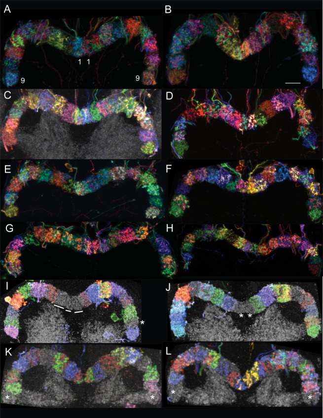
The protocerebral bridge comprises 18 glomeruli. MCFO-labeled protocerebral bridge neurons highlight individual glomeruli in distinct colors. The PB is also immunolabeled with nc82, so glomeruli not containing stochastically labeled cells are gray (see lines and asterisks). The protocerebral bridges of both female (C,D,F–L) and male (A,B,E) brains each have 18 glomeruli. Brains from three GAL4 lines are shown, although the presence of 18 glomeruli is universal among all lines. A–H: [R33A12], a mixture of PBG1–8.s-EBt.b-D/Vgall.b and PBG1–8.b-EBw.s-D/Vgall.b neurons; I,J: [R37F06], PBG2–9.s-EBt.b-NO1.b neurons; K,L: [R60D05], PBG1–8.b-EBw.s-D/Vgall.b neurons; K: see also Movie 1; L: see also Movie 2. Movies 1 and 2: Each movie shows a different PB with MCFO-labeled cells in the glomeruli. Between zero and two cells arborize in each glomerulus. Numbers identify each glomerulus and are color-coded according to the color of the cells that arborize in the corresponding glomeruli. Scale bar = 8 μm.
Figure 6.

Projection pattern between the PB and FBℓ1. A: nc82-labeled FB. This focal plane illustrates the medial and two neighboring teeth on each side of the midline. B: Distinction between the lateralmost and cryptic teeth of FBℓ1. The green arbor, consisting of boutons, is in the lateralmost tooth and originates from a PBG2–9.s-FBℓ1.b-NO3P.b neuron in G3L. The blue, bouton-rich arbor is in the cryptic tooth and arises from a PBG2–9.s-FBℓ1.b-NO3P.b neuron that arborizes in G2L [R65B12]. These FBℓ1 domains are also illustrated in Movie 3. C: PBG2–9.s-FBℓ1.b-NO3P.b neuron. D: Schematic representation of PB:FBℓ1 circuitry of the PBG2–9.s-FBℓ1.b-NO3P.b neuron. The glomeruli in which this neuron arborizes (G2–G9), the specific FB teeth they target and the lines connecting them, are similarly colored to more easily follow the projection pattern for this cell type. The numbers beneath each tooth of the FB refer to the glomeruli from which they receive input, and "i" and "c" refer to ipsilateral and contralateral. The arbors from pairs of neurons that target the same teeth intermingle within the FB domains, although for clarity the colors are separated in the schematic. At the second junction, between the FB and NO, the primary neurites from G9–G6 cross the midline to arborize in the contralateral noduli (not shown). The remaining projections, from G5–G2, have already crossed the midline and therefore do not cross the midline again. E: Two examples of FBℓl.b-NO3P.s-LAL.s.b-cre.s.b neurons [R44C06] highlight FBℓ1 teeth with tufts of boutons. Each tuft is located in a separate tooth with the exception of the central tooth, which houses two tufts; asterisks identify the tufts. A clear distinction between the left, lateral two teeth in the red example (right panel) is obscured in this focal plane, although the individual neurites leading to the tufts are evident and reveal the separate arbors. The two ventral tufts in both the green (left) and red (right) neurons that are not marked with asterisks arborize in the noduli. Movie 3 shows NO1, NO2 and a small portion of the FB. The green cell originates from G2L in the PB and arborizes in the cryptic tooth of the FB (labeled C). The blue boutons are in the most lateral tooth and course from G9R in the PB. The more medial green arbor (not labeled) arises from G8R. Left scale bar = 8 μm, right scale bar = 10 μm in E.
Architecturally, the "addition" of a ninth glomerulus would be expected to affect the anatomical correspondence and projection patterns between glomeruli in the PB and equivalent vertical partitions in the FB and EB, since the FB is reported to be divided into eight and the EB into 12–16 vertical divisions (Hanesch et al., 1989; Young and Armstrong, 2010b; Lin et al., 2013). These features are discussed below.
Following convention, G9 is the most lateral and the two G1s are the medial glomeruli. Most of the glomeruli closely approximate lima beans in shape, although those closest to the midline are more rectangular. The central two glomeruli (G1) occupy the smallest volumes. Unlike the equivalent vertical divisions in the FB (segments/columns) and EB (wedges and tiles, described below), the boundaries between the glomeruli are evident in nc82-labeled samples. In addition, they are generally more restrictive than the FB and EB vertical domains, in that individual PB cell arbors are predominantly, but not exclusively, confined within the boundaries of these units (see below).
Segmentation of the FB
The FB, as well as its corresponding neuropil, the CBU, is divided into horizontal layers, vertical columns, and anterior–posterior layers called shells (Hanesch et al., 1989). The PB neurons characterized here fill the entire anterior–posterior depth of the structure, so shells will not be discussed further. The number of layers in the Drosophila FB has most recently been estimated to be "roughly eight" (Young and Armstrong, 2010b) or six (Lin et al., 2013). nc82 immunolabeling reveals a low-resolution "stratigraphic column" of seven distinct layers in the FB, based on quality, texture, and intensity of the immunoreactivity, which reflect the density of synapses (Fig. 5A).
Figure 5.

Layers of the FB. A: nc82-labeled adult FB. Asterisks identify layers discriminated by their synaptic density and distribution. B–E: MCFO-labeled fan-shaped bodies. B: Layer 9 is the "cap" of the FB. A local interneuron that arborizes in two layers of the FB (left inset) terminates at sites presumed to be presynaptic at the top of the FB. It does not fill the entire cap (right inset, arrow); this unfilled tip may define yet another, more dorsal, layer. C: A red, large-field neuron arborizes in the FB between FBℓ1 and FBℓ2 (layer 1d/2v). This neuron defines either a separate layer or a sublayer of either FBℓ1 or FBℓ2. Layer 3 is not evident at this angle of orientation. D: MCFO of a brain from GAL4 line [R34E11] reveals a distinct, unlabeled layer 3 between layers 2 and 4, both of which are clearly delineated by MCFO-labeled neurons. E1: The dorsal layers 9, 8, and 6 are highlighted by MCFO-labeled neurons; layer 7 appears as a gap labeled only with nc82. A large-field neuron arborizes throughout only the dorsal half of layer 6 (the ventral half is labeled with nc82, as shown in E2), perhaps defining it as a separate layer. The exclusion of the red layer 8 neuron from layer 9 and the green layer 9 neuron from layer 8 substantiates the assignment of these domains as distinct layers [GAL4 line R34H05]. E2: High-magnification view of E1 with nc82 label included. Layers 5 and 7 are evident, as is the synapse-dense ventral region of layer 6 from which the green neuron in E1 is excluded. E3: Sagittal view of brain shown in panel E1 highlights the dorsal position of the green neuron in layer 6.
Volumes defined by the profiles of MCFO-labeled cells that arborize in the FB provide a higher-resolution map of FB layers. This more detailed neuronal landscape reveals there are at least nine layers (Fig. 5; abbreviated ℓ1–ℓ9). A particularly informative example is a local interneuron that arborizes in only two layers of the FB (Fig. 5B, left inset). In the example shown in Fig. 5B, the arbor is spiny in FBℓ8 and has output terminals in the dorsalmost layer, the "cap" of the FB, currently assigned as layer 9. The bouton-rich arbor is clearly confined to the dorsal layer of the FB (Fig. 5B), which is not revealed as a distinct layer in nc82-labeled specimens but instead blends with the next more ventral layer (Fig. 5A). Furthermore, the arbor does not completely fill the dorsal cap, possibly indicating there is yet another, even more dorsal layer (Fig. 5B, right inset, arrow).
A more subtle example is illustrated by a large field neuron with unilateral spiny branches in the superior protocerebrum (not shown) and a sparse apparently presynaptic arbor throughout a layer that resides between layers 1 and 2 of the FB (Fig. 5C, red, ℓ1d/2v). While this cell may help define a new, narrow layer, alternatively it may occupy an upper substratum of layer 1 or, more likely, based on nc82 labeling, a lower substratum of layer 2. FB layers 2–5 are shown in Figure 5D. Another large field neuron arborizes along the dorsal margin of the synapse-dense layer, identified here as layer 6 (Fig. 5E1–E3). If this layer, FBℓ6d, and the previously mentioned FBℓ1d/2v, are ultimately determined to be separate layers, there would be at least 11 layers in the FB.
The actual number of layers in the FB will likely remain unresolved until two prerequisites are met. First, the features of what constitutes a layer need to be formally defined. The two most likely options are to define them based on either function or anatomy, or perhaps as some combination of the two. Second, all neurons that arborize in the FB must be identified and consolidated into a single, standard brain so that their relative volumes can be compared directly.
Vertical striations evident in nc82-labeled FBs give the neuropil a columnar appearance. In addition, the arbors of small field neurons in the FB occupy horizontally constrained domains in the layers in which they arborize, lending a columnar appearance to the FB in samples with labeled neurons. In at least some cases, the margins of arbors in the FB were used to determine the width and, by extrapolation, the number of columns, although there is not a consensus on the number of columns in the FB. In Drosophila, Hanesch et al. (1989) suggest there are either 8 or 16, while Lin et al. (2013) favor eight. Strausfeld (1976) describes 14 staves in Musca and Calliphora and 8, each with two subunits, in Drosophila (Strausfeld, 2012) compared with Heinze and Homberg (2008), who describe 16 columns in the CBU of Schistocerca.
It has been assumed that the number of columns is identical in all layers. While a columnar architecture is evident in nc82-immunolabeled brains in all layers except the cap, the picture that is beginning to emerge from the work reported here is that neurons, including both PB-FB and FB neurons that do not have projections to the PB, do not organize themselves into columns in all layers of the FB. Rather, such a restricted pattern of arborization may be a phenomenon associated only with layers 1 through 5. (The only instance of columnar arbors in layers 4 and 5 comes from the PBG1–8.s-FBℓ3,4,5.s.b-rub.b cell.) A more relaxed columnar arrangement is evident in layers 4 through 8 (with the exception of the PBG1–8.s-FBℓ3,4,5.s.b-rub.b cell), in which the arbors of various cell types extend horizontally across a greater width than in layers 1 through 3 (e.g., PB.s-FBℓ6.b.ℓ3.s-Vga-s.b; see Fig. 3, as well as several FB local interneurons). Furthermore, the diminutive, dorsalmost layer, layer 9, which spans only approximately the medial sixth of the FB, is unlikely to have eight or more columns. Data analyzed here support this prediction: a columnar organization is not evident in layer 9 in nc82-labeled brains, and of the neurons analyzed to date, each neuron that arborizes in this layer has processes that extend throughout more than half of the layer. Even in layers 2 and 3, where a columnar organization is clearly evident, the boundaries are not restrictive, in that arbors from neighboring columns frequently overlap. For example, the apparently presynaptic arbors of cells that arborize in FBℓ2 and FBℓ3, PBG2–9.s-FBℓ2.b-NO3A.b, PBG2–9.s-FBℓ3.b-NO2D.b and PBG2–9.s-FBℓ3.b-NO2V.b (Fig. 3), occupy a geographic space that corresponds roughly to the upstream PB glomerulus in which these cells also arborize, although these arbors can show extensive overlap with those from cells in adjacent glomeruli. Finally, no PB-FB cells were identified in this study that target layers 7–9.
Published work has proposed either a one-to-one (Hanesch et al., 1989; Chiang et al., 2011) or two-to-one (Lin et al., 2013) correspondence between glomeruli in the PB and columns in the FB. In order to distinguish between these two possibilities and to reevaluate the options with the knowledge that there are 18 glomeruli in the PB, it was necessary to determine the number of columns in the FB. This number is difficult to evaluate given that the arbors of neurons overlap with one another, sometimes extensively. However, we show that the morphology of layer one (ℓ1) of the FB is unique compared to the other layers and therefore provides an unambiguous opportunity to count columns.
All layers of the FB have smooth dorsal and ventral margins except FBℓ1 (and possibly the FBℓ4/FBℓ5 boundary). The ventral margin of FBℓ1 is delineated by a total of seven distinct teeth resembling cogs, plus an additional two "cryptic teeth" that are elusive in that they are not evident in nc82-labeled samples, but only in specimens with the right combination of labeled cells. Five of the seven teeth are shown in the focal plane in Figure 6A; a cryptic tooth is seen in Figure 6B and Movie 3. The FB is shaped like a negative meniscus, curved such that the center is posterior to the edges, as previously reported (Hanesch et al., 1989; Strausfeld, 2012). The central tooth is most posterior and flanked on each side by three prominent and increasingly anterior teeth. The most lateral two cryptic teeth are the smallest and lie ventral and anterior to their nearest neighbors (Fig. 6B,D, Movie 3). The cell type PBG2–9.s-FBℓ1.b-NO3P.b (Figs. 3, 6C) reveals a total of nine columns in ℓ1 of the FB. These cells arborize in eight glomeruli (G2–G9) on each side of the midline. Cells from two glomeruli, one ipsilateral and one contralateral, project to each of the seven distinct teeth. The lateralmost, cryptic teeth, however, receive input from just one contralateral glomerulus each (Fig. 6D; the details of the wiring diagram are described below). PBG2–9.s-FBℓ1.b-NO3P.b cells therefore reveal a total of nine columns in layer 1 of the FB.
A second example of column number for ℓ1 is illustrated by the previously unreported cell type FBℓ1.b-NO3P.s-LAL.s.b-cre.s.b, which has distinct tufts of boutons in FBℓ1 (Fig. 6E). In this cell, there are four tufts per side and two centrally located tufts (both of which occupy the larger, medial tooth). Each tuft stems from a separate branch, and each branch arises from the primary neurite; these branches help to distinguish the tufts. The arborization pattern of this large-field neuron is consistent with the observation that there are a total of nine columns in FBℓ1. (One could argue that there are 10 columns since the two medial tufts are distinct. However, since the center tooth is a single, morphological unit, we opted to consider the center tooth a single column.)
Elaborate set of neuropil volumes partitions the ellipsoid body
The EB is shaped like a torus, or donut (Fig. 1). The arbors of neurons that innervate this central complex structure define multiple, distinct, but overlapping volumes within the EB. These arbors reveal a highly complex yet exquisitely well-organized tangle of synaptic inputs and outputs and hint at the sophisticated circuits of cells that target this structure. This work identifies new volumes and elaborates on previously defined volumes of the EB.
Layers/rings
The EB is partitioned along its radius into concentric annuli, or rings (Hanesch et al., 1989; Renn et al., 1999; Young and Armstrong, 2010b), of varying diameters. (Note that in other neuropterans the homologous subdivisions are layers rather than rings since the EB and homologous upper division of the central body, or CBL, are not circular.) The striking arbors of the "ring neurons" form virtually complete rings within the boundaries of the EB and help to accentuate these regions. The rings do not fill the anteroposterior depth of the torus (see below). The morphology of the ring neurons has been described elsewhere (Hanesch et al., 1989; Young and Armstrong, 2010b). As discussed for layers of the FB, an accurate and complete catalog of the number of rings in the EB will only be possible with an exhaustive analysis of all neurons that form ring-like arbors in the EB.
Shells
The EB is layered on its anteroposterior axis. Hanesch et al. (1989) cited two such layers and named them the anterior and posterior rings; Young and Armstrong (2010b) observed four such rings. Since the term "shell" was used to define similar anteroposterior layers in the FB (Hanesch et al., 1989), we will refer to such anteroposterior divisions of the EB as shells both to maintain a consistent terminology and so as to not confuse anterior and posterior rings with the concentric rings of the EB.
The studies reported here reveal three distinct, complete shells in the EB. The shells are evident in nc82-immunolabeled preparations and are highlighted more clearly in brains with labeled cells, particularly brains in which the ring neurons are labeled (Fig. 7). EB arbors fill the entire volume of the shells they occupy. Some cell types fill just one shell (e.g., Fig. 7A,B), whereas others fill more than one (Fig. 7C,D). The arbor of one cell type, the EB.w.AMP.s-Dga-s.b cell (Fig. 7D), extends the entire depth of the EB, populating the anterior, medial, and posterior shells (AMP). (More specifically, this cell has spiny arbors in all three shells—anterior, medial, and posterior—of an EB wedge, and bouton-type terminals in an undefined region surrounding the dorsal gall, which we call the Dorsal gall-surround.) A previously uncharacterized R1-like neuron, EBR1.b-cre.s, also occupies the anterior shell (not shown).
Figure 7.

EB shells and nubbin. A: Anterior (cyan and yellow) and medial (green) shells are highlighted with MCFO-labeled neurons whereas the posterior shell lacks signal (gray, nc82). Left panel is an off-axis frontal view to provide a sense of depth of the shells. Right panel is a sagittal view [R30F05]. B: Anterior (orange) and posterior (red) shells are highlighted by ring neurons; medial layer is unlabeled. Left panel is frontal view, right panel is sagittal view [R13D05]. C: Sagittal views of two EBs are shown. The EB arbors of tile cells, in this case PBG1–8.s-EBt.b-D/Vgall.b cells (green, top; yellow, bottom), fill just the posterior shell, whereas the PBG1–8.b-EBw.s-D/Vgall.b cell (red, top and bottom) fills both the posterior and medial shells. Arrows identify the anterior shells, which lack labeled arbors. D: Two EBs are shown in sagittal view. The EB arbor of EBw.AMP.s-Dga-s.b cells (blue and green) fills all three shells: posterior, medial. and anterior. Arrows again identify the anterior shell. E: Frontal and side views of a BU.s-EBnub.b neuron. The EB arbor is restricted to the anterior protuberance of the EB [R41G11]. This cell is not a PB neuron, but is used to show the morphology of the nubbin. Scale bar = 19 μm in E. See also Movie 4. Anterior is to the right for all side views. Movie 4: The red arbor of a BU.s-EBnub.b neuron fills the nubbin subregion of the EB.
Nubbin: a new anatomical feature of the EB
This work identifies a previously uncharacterized anatomical feature of the EB: a protuberance on the dorsal anterior face of the EB (Fig. 7E, Movie 4). Since it is an anteroposterior volume, it could be considered a partial shell. We named this region the nubbin (nub) because it is a projection that appears stunted and undeveloped. The nubbin is evident in nc82-labeled brains and, as with other brain regions and subdomains, is defined as a distinct volume in the EB by the arbors of a neuron, the BU.s-EBnub.b cell, which specifically targets this region of the EB (Fig. 7E; [R41G11]). Notably, this volume is not targeted by any other neurons identified to date.
Wedges and tiles
Two morphologically and functionally distinct volumes partition the EB into periodic compartments: wedges and tiles. Wedges radially segment the EB, resembling slices of a pie. Wedges extend the full radius of the torus and, as demonstrated here, occupy either just the posterior and medial shells of the EB, or all three shells, depending on the cell type (see below). As described for columns in the FB, arbors in wedges in the EB also do not respect strict boundaries; rather, arbors from cells within neighboring wedges overlap to varying degrees (see below). These subdivisions are named "sectors" in Hanesch et al. (1989), but the term "wedge" is preferred over "sector" since it implies a sense of depth not suggested by sector.
The second volume, the tile, has not been described previously. Tiles also segment the EB around the circumference of the torus, but unlike wedges they are a surface volume, restricted to the posterior shell of the EB. While all shells extend from the perimeter of the torus to the canal, this feature is not obvious in the posterior shell since the diameter of the canal is greater at the posterior than at the center of the torus. Consequently, in maximum intensity projections tile volumes do not appear to extend to the canal. As described for the FB and other EB volumes, a few boutons from cells in one tile can occupy a neighboring tile (see below).
Wedges and tiles are functionally distinct. To date, the only cell type that has been identified that arborizes in the PB and in wedges is spiny in the EB (PBG1–8.b-EBw.s-D/Vgall.b; Figs. 3, 8A,C1,C2; note that Lin et al., 2013, characterize the EB arbor in this cell as mixed, comprising both dendritic and presynaptic endings, see below). A second cell that does not arborize in the PB but does arborize in wedges is also spiny in EB wedges (EB.w.AMP.s-Dga-s.b, described above). On the contrary, the only two cell types identified to date that arborize in the PB and occupy the tile domain are bouton-rich in the tile (PBG1–8.s-EBt.b-D/Vgall.b and PBG2–9.s-EBt.b-NO1.b; Figs. 3, 8B,C1,C2,D1,D2).
Figure 8.

Wedge and tile cells. A: PBG1–8.b-EBw.s-Vgall.b. B: PB G1–8.s-EBt.b-Dgall.b. C1: PBG1–8.s-EBt.b-Vgall.b (left) and PBG1–8.b-EBw.s-Vgall.b (right) cells. C2: Same cells as shown in C1 with nc82 for reference. PB in left panel; EB and gall in center panel; dorsal gall, right panel. D1: PBG2–9.s-EBt.b-NO1.b cell. D2: Same cell as shown in D1 with nc82 for reference. PB shown in left panel and EB and NO1 in right panel. Note that the profile of the FB is replaced by that of the EB in more anterior focal planes. In the plane shown here, the FB is just beginning to give way to the EB, so the EB arbor appears to reside in the FB. PB: protocerebral bridge; EB: ellipsoid body; GA: gall; NO: nodulus.
There is a 1:1 correspondence between PB glomeruli and EB wedges for a given cell type
The circuitry that connects the structures of the central complex and its accessory neuropils resembles an intricate labyrinth. A cell-type-by-cell-type analysis of the underlying circuits reveals that, despite the apparent undecipherable confusion, cells for the most part adhere to a fundamental set of wiring rules. These are outlined in the sections that follow.
As with the FB, there is thought to be a 1:1 correspondence between PB and EB volumes. Hanesch et al. (1989) report between 12 and 16 sectors in the EB, whereas Strausfeld (2012) and Lin et al. (2013) propose there are 16. If such a 1:1 correspondence exists, this work raises two questions: whether there are 16 or 18 wedges and tiles, and, if there are 16, how the circuits are designed to accommodate the discrepancy. MCFO-labeled brains were used to glean insight into the anatomical organization of the EB with respect to the PB and to identify the number of divisions, both wedges and tiles, in the EB.
Of the PB-EB neurons analyzed to date, the maximum number of glomeruli targeted by a given small field PB-EB neuron is 16—no PB-EB small field neurons have been identified for which a single cell type targets each of the 18 glomeruli. Instead, those neurons that arborize in 16 glomeruli target either G1–G8 or G2–G9, leaving one glomerulus per side "empty," or without an arbor. Consequently, we expect either that: 1) there are 18 volumes in the EB (both wedges and tiles), and two of the 18 lack arbors, or 2) there are 16 volumes and there is a 1:1 correspondence between the PB and EB.
PBG1–8.b-EBw.s-D/Vgall.b cells (Figs. 3, 8A,C1,C2) represent the only cell type identified so far that arborizes in both the PB and in wedges in the EB. Although Lin et al. (2013) characterize the EB arbor of this cell as "mixed," comprising both pre- and postsynaptic domains, our analysis of the morphology and polarity (using anti-synaptotagmin) of the transmission is inconclusive for presynaptic terminals in the EB. To determine the number of wedges in the EB, the MCFO technique was used to label PBG1–8.b-EBw.s-D/Vgall.b cells at both low and high density (Fig. 9). Sparsely labeled brains were used to: 1) establish the number of wedges in the EB and 2) map the circuits between individual glomeruli and small increments—equivalent to half-hour increments on a clock face—of the EB. This "circuitry template" enabled a "dissection" of the more complicated, densely labeled brains, which were effectively used to confirm the results of the sparsely labeled brains.
Figure 9.

The EB comprises 16 wedges and 32 demi-wedges. A1–A3: Confocal images and schematics of MCFO-labeled protocerebral bridges and corresponding ellipsoid bodies from three densely labeled brains. Cell type: PBG1–8.b-EBw.s-D/Vgall.b. Colors used in the schematics do not necessarily correspond to the colors in the confocal images because of color redundancy in the data panels. Two of the 41 labeled glomeruli shown in these three brains had three labeled cells each: G4R and G8R in A1. Note that in A1, the green cell in G4R transitions to yellow in the EB due to ramping of the laser power during imaging. To minimize confusion, this cell is green in the schematic in both the PB and EB. Brains shown in A1 and A3 are from line [R60D05]; brain in A2 is from [R33A12]. B,C: Demi-wedges are illustrated in these high magnification confocal images of small portions of two ellipsoid bodies. Two cells are labeled in the glomeruli (insets) corresponding to the wedges shown. For each example, three panels are shown. The first shows both cells (or both colors), followed by each color shown separately to illustrate the gap, or demi-wedge, occupied by the partner cell. The asterisks identify the two demi-wedges corresponding to a single wedge. Note that while there is some overlap between these EB arbors, there is a clear distinction between the two arbors that originate from the same glomerulus. B: An enlargement of a portion of the EB shown in A1; the region of interest is G4L, which contains a red and blue cell, shown in inset. See also Movie 5. C: The wedge labeled with blue and red arbors (9:00, red and yellow asterisks) exemplifies an instance in which the arbors from two cells from the same glomerulus both occupy the entire wedge. These cells arborize apparently presynaptically in G3R. The blue and green cells occupy adjacent demi-wedges of a single wedge and have their PB bouton arbors in G8L (inset). Brain shown in C is from line [R60D05] and is the same brain shown in Movie 6. Movie 5 The red and blue cells highlighted here with asterisks occupy adjacent demi-wedges of the same wedge. Cells both arborize in G4L of the PB (shown in Fig. 9). The gaps that appear when the red and blue channels are turned off are the demi-wedges. Movie 6 illustrates two cells with bouton-type arbors in a single glomerulus, G8L (labeled G8), and postsynaptically in adjacent demi-wedges in the EB. One cell is green, the second is blue; they arborize in the EB at ∼8:00. The densest regions of the spiny arbors in the demi-wedges, the spines (as in backbones), are marked with the paired blue and green asterisks. There is a second green cell that arborizes at about 11:00 in the EB that does not arise from G8L (yellow asterisk). A second pair of cells, one red and one blue (paired red and blue asterisks), projects from G3R (glomerulus not shown). These cells arborize in the EB at 10:00 and overlap extensively in either the same wedge or demi-wedge. The Z series of the blue cell illustrates the projection of the cell (orange arrow identifies primary neurite) that arborizes in G8 to the lower blue arbor in the EB (orange asterisk). Similarly, the Z series of the green cell shows the projection from G8 to the green demi-wedge in the EB (purple asterisk), although this path is more difficult to follow.
The projections of PBG1–8.b-EBw.s-D/Vgall.b cells in three densely labeled brains, each containing 13–14 labeled glomeruli (of 16 possible, since G9 lacks an arbor from this cell type), were tracked from PB glomeruli to EB wedges (Fig. 9, Movies 5 and 6). When like-colored primary neurites from different glomeruli overlapped one another, the circuits established from sparsely labeled brains were used as a guide to "untangle" their intersecting paths to their respective wedges in the EB. As necessary, color channels were toggled on and off to create different combinations of colors for each cell so that the precise arborization domains for each cell could be determined. This strategy, in combination with the circuitry template, enabled the following five conclusions to be drawn. 1) There are 16 wedges, and arbors sometimes fill just half a wedge ("demi-wedges"). There is no discernible anatomical distinction between cells that occupy entire vs. demi-wedges, other than the boundaries of the wedge arbor. 2) When two cells are labeled in a single glomerulus, their arbors either overlap completely in a given volume of the EB, or they occupy adjacent demi-wedges. Of the 41 glomeruli labeled in these three brains, most had one or two labeled cells in a single glomerulus and just two had three labeled cells. In both instances of glomeruli containing three labeled cells, the arbors of two of these cells overlapped, whereas the third occupied an adjacent volume; it is likely that the two volumes occupied by these three cells represent demi-wedges of a single wedge. When only one cell was labeled in a glomerulus, it generally appeared to fill the entire wedge, although in some instances there was an unlabeled adjacent volume. There are likely to be more blank demi-wedges than can be discerned in these brains, but given the high density of labeled cells and the fact that spiny branches can spill into neighboring volumes (see 4, below), unlabeled demi-wedges are difficult to detect. 3) There is a 1:1 correspondence between glomeruli and EB wedges: Wedges and demi-wedges receive arbors exclusively from cells in a single glomerulus and arbors from a single glomerulus arborize in only one wedge or two paired demi-wedges. In other words, an arbor arising from a cell in one glomerulus has not been seen to share either a wedge or a demi-wedge with an arbor of a cell arising from a different glomerulus. (Note that this observation is primarily gathered from the sparsely labeled brains.) 4) Arbors from neighboring wedges can overlap at the edges of their arborizations domains, sometimes quite extensively (Fig. 10). 5) Arbors arising from cells that target G1 and G5 target wedges at clock positions 6:00 and midnight, respectively, with the left and right counterparts for each of these glomeruli falling on opposite sides of this midline (at approximately 11:30–12:00/12:00 to 12:30 and 5:30–6:00/6:00–6:30; see below for projection map details).
Figure 10.

Arbors in EB wedge and tile domains are not confined within strict boundaries. A: Spiny arbors of three PBG1–8.b-EBw.s-D/Vgall.b cells in three adjacent EB wedges are shown: The central green cell's arbor is bordered dorsally by the red cell and ventrally by the blue cell. The spiny arbors of PBG1–8.b-EBw.s-D/Vgall.b cells in wedge domains are dense centrally, resembling a backbone, and become increasingly sparse peripherally. The lines identify the approximate extreme lateral limits of spiny arbors from adjacent wedges. While there is variability in the extent of the domains of arborizations, arbors do not extend beyond the adjacent EB domain. The degree of overlap of arbors in neighboring wedges is evident in the examples shown in which color channels were separated to illustrate the individual neurons. B: Arbors consisting of boutons also extend into neighboring tile domains, illustrated in these five examples. Asterisks identify boutons from PBG1–8.s-EBt.b-D/Vgall.b cells that intrude into neighboring tile domains. C: Schematics illustrating the extension of spiny (top) and bouton (bottom) arbors into adjacent domains.
Two key conclusions can be drawn about wedges, at least for the only cell type so far identified to arborize in them, the PBG1–8ps-EBw.s-D/Vgall.b cell. First, there are 16 wedges in the EB, one for each glomerulus arborized by this cell type (G1–G8), and second, arbors of some cells occupy the entire wedge, whereas others occupy just half a wedge. Whether these cells—full wedge vs. demi-wedge—should be classified as distinct cell types or not is debatable; answering this question will require additional physiological and behavioral studies.
Consistent with the results described above, cell counts of the total population of PBG1–8.b-EBw.s-D/Vgall.b cells in three brains (n ∼45, 39, and 36) suggest that between two and three cells target each of the 16 glomeruli (n divided by 16 glomeruli). It is not obvious how these two to three cells are distributed among the 16 glomeruli. The data shown in Figure 9 reveal that the simplest scenario, in which there are three cells per glomerulus, one that occupies the full wedge, and one for each demi-wedge, cannot be the case. Since as many as three cells can arborize in a single glomerulus and its corresponding wedge, an alternative possibility is that certain glomeruli are always targeted by three cells, and others always by two cells. No more than three cells were seen to arborize in a single glomerulus in these studies, perhaps excluding yet more complex combinations. Finally, it is possible that the volume occupied by the arbors of a particular cell is determined by a stochastic developmental event.
Eight tiles constitute the EB
As previously noted, the available evidence suggests that tiles are output domains in the EB, whereas wedges are input domains, and that tiles innervate just the posterior shell of the torus, whereas wedges arborize in both the posterior and medial shells, as well as the anterior shell in the case of the EB.w.AMP.s-Dga-s.b cell. A third significant difference between these two volumes is that tiles are targeted by cells from two glomeruli rather than just one. Consequently, there are eight tiles rather than 16, and tiles occupy a wider volume than do wedges (Fig. 11).
Figure 11.

The EB comprises eight tiles. A–D: MCFO-labeled protocerebral bridges and corresponding ellipsoid bodies from four brains from line [R37F06]. The cell type labeled is PBG2–9.s-EBt.b-NO1.b; the noduli are not shown. The unlabeled gap in the center of the PB reflects the fact that this cell type does not arborize in G1. Note that the colors in the PB are not always preserved for a given cell in the EB due to laser adjustment (ramping) through a confocal stack. For example, in B the cell that arborizes in G2R is purple in the PB and blue in the EB. In this same brain, G9L is pink in the PB due to the presence of two labeled cells, one green and one blue (see inset of PB, in which the green and blue channels were independently toggled off to demonstrate the presence of the two neurons); the bouton arbors from these two cells are clearly blue and green in the EB. The eight tile volumes are evident in the EB; the glomeruli from which they originate are indicated next to each EB tile. In panel A, the EB is shown twice, the second time with the green channel turned off to reveal arbors that are obscured by the green channel (i.e., the red arbor from 4R).
Just two cell types have been identified that connect glomeruli in the PB to tile domains in the EB: PBG1–8.s-EBt.b-D/Vgall.b (Figs. 3, 8B,C1,C2) and PBG2–9.s-EBt.b-NO1.b (Figs. 3, 8D1,D2). As with the PBG1–8.b-EBw.s-D/Vgall.b cells (Figs. 3, 8A,C1,C2), the two PB-EB tile cells are not represented in all glomeruli: PBG1–8.s-EBt.b-D/Vgall.b cells do not arborize in G9, and PBG2–9.s-EBt.b-NO1.b cells do not target G1. The details of the connections between the PB and EB domains are described below.
Noduli are composed of subcompartments
nc82 labeling reveals three distinct noduli, each with a unique size and shape (Fig. 12) (Young and Armstrong, 2010b). The dorsalmost nodulus, "NO1," is the smallest, triangular in shape in frontal sections, and is displaced anteriorly. NO1 is also the brightest nodulus in nc82-labeled brains and, since nc82 is thought to label T-bar ribbons, this brighter signal may therefore reflect a greater density of presynaptic sites, suggesting that NO1 has the highest synaptic density of the three noduli. The medial nodulus, NO2, is somewhat rectangular in shape in a frontal view and protrudes slightly more anteriorly than NO1. The ventralmost nodulus, NO3, is more square than NO2 and occupies the largest volume of the three. NO2 and NO3 have distinct subcompartments that are revealed by distinguishable texture, contrast, and intensity in nc82-labeled samples and, more definitively, by arborization domains of cells that specifically target these subregions. NO1 may also have subcompartments (see below). The nomenclature of "subcompartments" rather than separate noduli was chosen because these subregions are so tightly juxtaposed that there is no obvious break in nc82-labeling, and therefore no separation, between the units (Fig. 12B,D) as there is between NO1, NO2 and NO3. Cell projections to these subcompartments are discussed below.
Figure 12.

Anatomy of subcompartments of the noduli. A: Frontal view of NO1 pairs illustrating the apparent subdivision of NO1 into medial and lateral halves. Noduli are from [R65B12] (A1,A2) and [R12D09] (A3,A4). B: Frontal (B1,B3) and sagittal (B2) views of nc82-labeled (B1,B2) and MCFO-labeled noduli (B3) illustrating the subcompartments of the noduli. B3 is from line [R65B12]. C: Frontal (C1) and sagittal (C2,C3) views of subcompartments of noduli. C2 shows the left set of noduli, C3 shows the right noduli of a brain from line [R34H05]. D: Sagittal views showing labeled neurons in NO2V from line [R37F06]. Black asterisk marks NO1. E–G: Sagittal views of MCFO-labeled subcompartments of noduli from [R65B12]. (Note that in panel E1 the brighter label in NO3P is bleed-through from the neuron labeled in E2.) F,G: The distinction between the three subcompartments of NO3 is illustrated using the MCFO technique. See accompanying Movie 7. Anterior is to the right for all sagittal views. Movie 7: NO1, the two subcompartments of NO2 and the three subcompartments of NO3 are clearly distinguished in this movie. Colored labels correspond to the colors of the cells that fill various compartments. NO1, NO2V, and NO3P are labeled only with nc82.
NO1
There appears to be a medial–lateral compartmentalization of NO1, although this division is less compelling than are the subdivisions of NO2 and NO3 (described below). First, nc82 labeling is uniform across NO1, which is not the case with NO2 and NO3. Second, just one cell type identified to date can arborize exclusively in either the medial or lateral half of a dorsal nodulus. Of the ∼35 GAL4 lines examined for this study, only two cell types arborize in NO1 and only one has been identified that connects the PB to NO1 (PBG2–9.s-EBt.b-NO1.b). The arbors of 64% (28 of a total of 44) of observed cells of this type fill the entire nodulus. In 30% (n = 13) of cases, the arbor is restricted to the medial half of the nodulus (Fig. 12A1–A3). The arbors in the remaining 7% (n = 3) filled only the lateral half of the nodulus (Fig. 12A4).
Cells in each of the eight glomeruli associated with this cell type, G2–G9, produce arbors that can fill the entire nodulus. However, it is intriguing that the cells that arborize only in the medial half of the nodulus arise from even glomeruli (with 8/13 arising from G6), and that the three cells that arborize only in the lateral NO1 all arise from G5. While the significance of the predisposition for the medially arborizing subset of cells to arise from even glomeruli, with a majority from G6, and the laterally arborizing cells to arise from G5 is unclear, these observations suggest that at least in most cases communication from G5 and G6 is restricted to either the medial or lateral half of NO1 as part of a functional plan.
In addition to this mediolateral compartmentalization of information within NO1, an unusual feature of this nodulus adds further support to the argument that it is compartmentalized: nc82 signal in NO1 sometimes appears divided into medial and lateral halves, a phenomenon not seen in the other noduli (not shown). While the identification of additional cell types that show a medial-lateral preference within NO1 is necessary to confirm such compartmentalization of NO1, a selective distribution of information seems likely.
NO2
NO2 comprises two subcompartments, a large dorsal (NO2D) and a smaller, ventral (NO2V) domain (Fig. 12B–G, Movie 7). NO2V resembles a pancake-like pedestal for NO2D in frontal sections (Fig. 12B–G). In rare cases, cells that arborize in NO2V also extend a thin flange anteriorly and dorsally, partially enwrapping NO2D (not shown). NO2D is less intensely labeled with nc82 than NO2V, and so may contain less densely packed synaptic sites (Fig. 12B1,B2).
NO3
NO3 is composed of three domains: the largest, posterior domain, NO3P; the smallest, medial domain, NO3M; and the most anterior domain, NO3A, which abuts NO3V (Fig. 12B–G, Movie 7). NO3P and NO3A are unambiguously distinct domains, and even in nc82-labeled brains it is easy to distinguish them, with NO3A having less intense signal and probably therefore being the less synaptically dense subcompartment (Fig. 12B2). The distinction between NO3M and NO3P is less obvious since, qualitatively, the nc82 label is identical in these two subcompartments. However, the distinction is unambiguous in brains with labeled cells that target subsets of these compartments (Fig. 12E–G). (Note that Lin et al., 2013, describe four noduli. It is likely that their NO3 and NO4 correspond to what we describe as NO3A for NO3 and NO3P+NO3M for NO4.)
Gall comprises three subcompartments
The gall (GA) is a distinct, paisley-shaped neuropil situated on the "shoulders" of the LAL (Figs. 1, 3). Ito et al. (2014) consider it a subregion of the LAL, but this work suggests it is an independent neuropil adjacent to the LAL. Our analysis of neurons that target both the PB and the gall reveal that the gall consists of three subdomains. Two large subdomains compose the bulk of the gall and were also described by Lin et al. (2013), a dorsal (D) and a ventral compartment (V; also the most anterior of the three subunits; Fig. 13). The previously undescribed minor subdomain is the most posterior volume and lies at the dorsal tip of the gall, earning it the name "gall tip" (Fig. 13). All three compartments are targeted in a cell type-dependent manner. Cells that arborize in the dorsal gall are excluded from the gall tip. Only one cell type has been identified that targets the gall tip (see below).
Figure 13.

Gall subcompartments. A: The three subcompartments of the gall are delineated by cells labeled with the MCFO technique. Subcompartments are labeled in each panel. T: gall tip. D: dorsal gall. V: ventral gall. The gall tip is identified by PBG9.s-EB.P.s-ga-t.b; the D and V gall are identified by PBG1–8.b-EBw.s-D/Vgall.b and PBG1–8.s-EBt.b-D/Vgall.b cells. B1–B3: Adjacent glomeruli (top) and corresponding galls (bottom) containing cells labeled using MCFO. nc82 is gray channel in all panels. B1,B2: PBG1–8.b-EBw.s-D/Vgall.b (from line [R60D05]) and B3) PBG1–8.s-EBt.b-D/Vgall.b cells (from line [R33A12]). B1: Orange cell is in G7 and arborizes in the dorsal gall; blue cell is in G6 and arborizes in the ventral gall. B2: Blue cell is in G8 and the ventral gall; red cell is in G7 and the dorsal gall. The apparent gap between the red and blue cells in the glomeruli is not an intervening glomerulus, but is a consequence of both a slightly buckled PB between G7/G8 and the fact that the blue arbor does not completely fill G8. B3: Red cell is in G4 (top) and the ventral gall (middle, frontal view), blue cell arborizes in G3 (top) and the dorsal gall (middle). Lower panel is a side view of the gall to illustrate that the apparent overlap of the red and blue arbors in the frontal view is a consequence of the fact that the D and V domains are staggered on the D/V axis.
Neuronal circuits between the protocerebral bridge and ellipsoid body
The various cell types that project between the PB and volumes in the EB follow the same general trajectories, although there are cell type-dependent differences in the details of the circuit diagrams, largely for two reasons. First, since there are 8 tiles and 16 wedges, the projection patterns between glomeruli and EB volumes are necessarily distinct. Second, individual cell types project to different subsets of glomeruli (for example, G1–G8, G2–G9, or exclusively G9 in the case of the PBG9.b-EB.P.s-ga-t.b cell, described below). Consequently, while the overall projection pattern is preserved in these unique cell types, the precise correspondence between a given glomerulus and a specific geographic location in the EB differs.
To map the circuits between the PB and the EB, the projections of all cell types that arborize in both the PB and EB were traced. For wedge cells, the projections from the PB to EB wedges were followed in dozens of brains sparsely labeled for the PBG1–8.b-EBw.s-D/Vgall.b cell type and in three densely labeled brains (per brain, 13–14 labeled glomeruli of 16 possible, since G9 is not targeted by this cell type) were traced. The circuitry template derived from more sparsely labeled brains was used as a scaffold to dissect the more dense, complex patterns. Brains in which PBG2–9.s-EBt.b-NO1.b and PBG1–8.s-EBt.b-D/Vgall.b cells were labeled were used to map the circuits between the PB and EB tiles.
The primary wiring principle is that the glomeruli of the PB effectively map linearly onto the EB. The projections from left to right and right to left are mirror symmetrical to one other (Figs. 14, 15). Each half of the PB completely enwraps the EB, with the left half wrapping clockwise and the right half wrapping counterclockwise around the EB. The alignment of the projection pattern from PB to EB can be most readily visualized if the EB is filleted at its antapex (6:00 on an analog clock face) and stretched flat to derive the ancestral, linear form of the EB characteristic of non-Drosophilids. For both wedge and tile cells, the most lateral glomerulus from the left half of the PB aligns to the volume that lies approximately between 7:00 and 8:00 on a clock face, whereas the most medial volume from the left half aligns with 6:00 (∼5:30–6:30; Figs. 14, 15). For the right half of the PB, the most lateral glomerulus aligns to the volume approximately between 4:00 and 5:00 and the most medial glomerulus aligns with 6:00.
Figure 14.

Connectivity between the PB and EB tiles. Schematics illustrating the projection patterns between the PB and EB tiles for two cell types, each of which targets a different subset of glomeruli. Schematics were derived from MCFO-labeled brains. Top: PB, middle: EB; bottom: filleted EB, as described in text. Glomeruli and their target EB volumes are color-matched. The numbers below the PB identify each of the glomeruli, whereas the black text around the EB denotes coordinates of an analog clock for use as reference. A: This wiring scheme represents the cell type PBG2–9.s-EBt.b-NO1.b, which does not arborize in G1 (gray in PB). Two cells, one ipsilateral and one contralateral, arborize in each tile. The three distal glomeruli project ipsilaterally in the EB, G6 and G2 occupy the midline volumes (the zenith and nadir, respectively), and G3–G5 project contralaterally in the EB. This linear projection pattern is readily seen by comparing the PB to the filleted EB. B: Wiring scheme for PBG1–8.s-EBt.b-D/Vgall.b cells, which do not arborize in G9 (gray in PB; [R33A12]). The same basic circuitry scheme illustrated in A applies to this cell type, but the ipsilateral/contralateral split is shifted laterally by one glomerulus since EBt.b-D/Vgall.b cells do not arborize in G9 but do arborize in G1. Therefore, the three most lateral glomeruli project ipsilaterally, G5 and G1 arborize in the midline volumes (the apex and antapex, respectively), and G4–G2 project to the contralateral EB. PBG1–8.s-EBt.b-D/Vgall.b cells in even-numbered glomeruli project to the ventral gall whereas odd-numbered glomeruli project to the dorsal gall (labeled D and V above each glomerulus of the PB).
Figure 15.

Connectivity between the PB and EB wedges. This schematic was constructed based on MCFO-labeled PBG1–8.b-EBw.s-D/Vgall.b cells, which do not project to G9 (gray in PB). Schematics of the PB, EB, and filleted EB are shown. Between zero and three cells are labeled in each glomerulus. Alphanumeric labels on the EB and filleted EB indicate the glomeruli from which cells project to each volume; the number refers to the glomerulus number, R is shorthand for right, and L for left. Alternating wedges are filled with gray or white and demi-wedges are indicated by a solid line that divides each wedge. Various combinations of wedge and demi-wedge arbor fills are illustrated. For example, G8R illustrates an example with three labeled cells; the purple and yellow occupy one demi-segment in the EB, the green occupies the other demi-segment of the same wedge. G1R has two labeled cells, both of which fill the entire EB wedge that corresponds to G1R. G5L and G3R each have just one labeled cell, but G3R fills its entire corresponding wedge, whereas G5L fills just a demi-wedge. As with PBG1–8.s-EBt.b-D/Vgall.b cells (above), PBG1–8.b-EBw.s-D/Vgall.b cells project to either the dorsal or ventral gall in the same glomerulus-specific fashion: even-numbered glomeruli project to the ventral gall whereas odd-numbered glomeruli project to the dorsal gall, as indicated by the D and V designations above the PB.
The second principle is collectively illustrated by PBG1–8.b-EBw.s-D/Vgall.b cells (Fig. 15) in conjunction with the two tile cell types: PBG2–9.s-EBt.b-NO1.b (Fig. 14A) and PBG1–8.s-EBt.b-D/Vgall.b (Fig. 14B). The same strategy used to map the circuits of PBG1–8.b-EBw.s-D/Vgall.b cells, described above, was used to map the wiring diagrams for the tile cells. As previously noted, PBG2–9.s-EBt.b-NO1.b cells are absent from G1, whereas both PB G1–8.b-EBw.s-D/Vgall.b and PBG1–8.s-EBt.b-D/Vgall.b cells are not represented in G9.
The second principle accommodates three features of the central complex: 1) There is a disparity between the number of volumes in the PB (18) and EB (16 wedges or 8 tiles); 2) Information flow is evenly distributed between the two brain hemispheres, as the brain generally is bilaterally symmetric; 3) Most neurons cross the midline at some point in their trajectories; since cells of the central complex typically arborize in three structures, cells can remain ipsilateral between the first and second neuropils and cross the midline between the second and third neuropils, or they can cross the midline between the first and second neuropils. To maintain a balanced distribution of information flow, the point of crossover for cells that stay ipsilateral between the first and second substructures shifts by one glomerulus in cells that arborize in G1–G8 versus those that arborize in G2–G9 so that four glomeruli per side stay ipsilateral at the first junction and four cross contralaterally at the first junction. More specifically, for cells that arborize in G9–G2, G9–G6 stay ipsilateral at the first junction and G5–G2 cross the midline at the first junction (PB-EB; Fig. 14A), whereas for cells that target G8–G1, G8–G5 remain ipsilateral at the first junction and G4–G1 cross the midline at the first junction (Figs. 14B, 15; note that for tiles, two volumes are situated on the midline, one at 12:00 and the other at 6:00). Therefore, a given glomerulus does not correspond to one single volume in the EB. Rather, the correspondence between each glomerulus and its target volume in the EB depends on the cell type.
The circuits also differ slightly for cell types that arborize in the two types of EB volumes because there is a difference in the number of EB subdivisions: 16 wedges and 8 tiles. The 2:1 correspondence between glomeruli and EB tiles results in one ipsilateral and one contralateral glomerulus contributing cells that arborize in the same EB tile. The arbors in a given EB tile are not segregated, but rather are intermingled (Figs. 10, 11, 14). In contrast, there is a 1:1 correspondence between glomeruli and EB wedges: Cells in each glomerulus target separate wedge volumes in the EB and, in some cases, two cells from a single glomerulus occupy separate demi-wedges of the same wedge. In the case of circuits for cell types that arborize in G1–G8, the EB tile and wedge regions that correspond to specific glomeruli (wedges) or pairs of glomeruli (tiles) are identical. (For example, both G1 tile cells in Fig. 4B and G1 wedge cells in Fig. 15 target the 6:00 region in the EB.) For cell types that occupy G2–G9, corresponding regions in the EB shift by one volume, but the correspondence is effectively the same (compare Figs. 14B and 15 to Fig. 14A; in the G2–G9 cell type, it is the G2 cells, not the G1 cells mentioned above, that target the 6:00 region in the EB). In other words, although G8R and G2L (Fig. 14B) or the equivalent G9R and G3L (Fig. 14A) for tile cells occupy a single volume (roughly corresponding to clock position 4:00 to 5:00), the geometric coordinates of this volume are the same as the combined volume occupied by the corresponding G8R and G2L wedge cells (4:00–5:00). Finally, whereas tile volumes straddle the midline (both 6:00 and 12:00), the wedge volumes do not, but instead fall to either side of the midline.
Connectivity principles for the protocerebral bridge to the fan-shaped body parallel those between the protocerebral bridge and ellipsoid body
The unique, tooth-like morphology of FBℓ1 enabled the number of columns to be defined in this layer. It also helped reveal the connectivity between the PB and layer 1 of the FB by mapping the trajectories of PBG2–9.s-FBℓ1.b-NO3P.b cells between the PB and FBℓ1. As with PBG2–9.s-EBt.b-NO1.b cells, PBG2–9.s-FBℓ1.b-NO3P.b cells are represented in all glomeruli except G1.
Cells in G9, G8, and G7 map linearly and ipsilaterally onto the FB (Fig. 6D). The arbors of cells from G9 occupy the lateralmost prominent tooth (not the cryptic tooth described above). Cells from G8 target the next, more medial neighbor, and cells from G7 project to the tooth adjacent to the central tooth. Both G6 cell arbors project to the large, central tooth, and those from G5, G4, and G3 arborize in progressively more lateral teeth on the contralateral side, with G3 cells occupying the most contralateral, prominent tooth. As a consequence of this projection pattern, the ipsilateral G9 cell arbors coarborize with the contralateral G3 cell arbors, the ipsilateral G8 cell pairs with the contralateral G4, and the ipsilateral G7 cell pairs with the contralateral G5. This wiring diagram is effectively identical to that seen between the PB and EB for PBG2–9.s-EBt.b-NO1.b cells (Fig. 14A). In a wiring scheme that parallels that described for the PB-EB projections, the expectation is that the cells in G2 would project to the FB's equivalent geographic location of the antapex (i.e., the most lateral domains in the filleted EB and the cryptic teeth in FBℓ1)—and they do (Fig. 6D). However, unlike the other teeth of FBℓ1, which receive input from both an ipsilateral and contralateral cell, the arbors that arise from cells in G2 appear to be the sole occupants of their FBℓ1 domains. These domains are not readily apparent in nc82-labeled brains, but can be distinguished in samples in which either or both of the contralateral G9 and ipsilateral G3 cells are labeled (Fig. 6B). The cryptic tooth is ventral and anterior to the volume occupied by G9 and G3 cells, although it is not clear if the cryptic tooth is a separate tooth or just a separate subdomain of the most lateral prominent tooth to which the cells of G9 and G3 project. Therefore, at least for the PBG2–9.s-FBℓ1.b-NO3P.b cell type (Figs. 3, 6C), FBℓ1 comprises either nine or seven columns, with cells of the most lateral cryptic teeth providing output from just one glomerulus and those of the remaining columns providing output from two glomeruli each (Fig. 6D).
The projections for the PB-FB-NO neurons PBG2–9.s-FBℓ2.b-NO3A.b, PBG2–9.s-FBℓ3.b-NO2D.b, and PBG2–9.s-FBℓ3.b-NO2V.b are essentially identical to those shown in Figure 6 in that cells from the most lateral four glomeruli stay ipsilateral in their projections to the FB, whereas those from the most medial four glomeruli cross to the contralateral side of the FB. The projection map is less precise for layers 2 and 3 because the arbors of cells in these layers are not confined to defined domains as they are to the teeth of layer 1 (the PBG2–9.s-FBℓ1.b-NO3P.b cell in Fig. 6) and therefore overlap somewhat with one another. While we did not have a sufficient number of PBG2–9.s-FBℓ1.b-NO3M.b cells to perform a comprehensive analysis, the circuitry is consistent with the diagram derived for PBG2–9.s-FBℓ1.b-NO3P.b cells (Fig. 6D).
The PB-FB-NO cells described above constitute the isomorphic set of neurons that give rise to the so-called vertical fiber system (Hanesch et al., 1989). The early Golgi-based account differs in two ways from the revised account provided here. First, the early description states that all cells maintain ipsilateral projections between the PB and the FB and do not cross the midline until they course from the FB to the noduli. The revised, MCFO-based account described above instead indicates a more typical projection pattern in which only cells from the lateral four glomeruli remain ipsilateral between the PB and FB. Second, the revised account reveals that the vertical fiber system does not include cells from G1, as none of the PB-FB-NO cells arborizes in G1.
PB-FB-NO circuits are highly restricted in the FB
Brains immunolabeled to visualize all neurons portray an image of absolute chaos with a dense network of connections coursing through the collective neuropils. An MCFO-based "dissection" of these connections reveals a surprisingly limited connectome between neuropils. For example, there is a great deal of specificity in central complex regions that provide output to the noduli. As noted above, just one cell type has been identified that connects the PB to NO1 (PBG2–9.s-EBt.b-NO1.b; Figs. 3, 11, 14A). Of the cells identified to date, a similarly small number of cells connect the PB to NO2 and NO3. Furthermore, there is specificity in the connections between certain layers of the FB and subcompartments of the noduli.
The common themes among the cell types that connect the PB to NO2 and NO3 are: 1) the FB serves as the second synaptic junction; 2) the cells all have spiny arbors in the PB and bouton-type arbors in the FB and noduli; and 3) none of these cells is represented in G1, so, to date, no direct communication between G1, the FB, and the noduli (nor even between G1 and the noduli) has been identified. Of the PB neurons identified, those that arborize in both the dorsal and ventral compartments of NO2 communicate directly with only layer 3 of the FB via PBG2–9.s-FBℓ3.b-NO2D.b and PBG2–9.s-FBℓ3.b-NO2V.b (Figs. 3, 16A,C,D). NO3P and NO3M receive their input from the PB via layer 1 of the FB and the cell types PBG2–9.s-FBℓ1.b-NO3P.b (Figs. 3, 16C, 16A) and PBG2–9.s-FBℓ1.b-NO3M.b (Figs. 3, 16A,E), while NO3A receives its input from the PB via layer 2 of the FB from the PBG2–9.s-FBℓ2.b-NO3A.b cell (Figs. 3, 16A,B). In summary, G1 does not communicate directly with any of the noduli; the PB does not communicate directly with NO1 via the FB, but rather via the EB; NO2 communicates directly with only layer 3 of the FB, NO3A only with layer 2, and NO3P and NO3M with only layer 1.
Figure 16.

Connectivity between the FB and noduli. A: The schematic illustrates the circuits between three layers of the FB—ℓ1, ℓ2, and ℓ3—and the subcompartments of the noduli to which the cells from these layers project. For clarity in illustrating the FB-NO connections, since the three NO3 subcompartments are not visible in a frontal view, noduli are shown in the schematic in a sagittal view (as in Fig. 12E2); inset of NO is frontal view. Arrows indicate projections from the PB. NO1 is not directly wired to the FB. B: PBG2–9.s-FBℓ2.b-NO3A.b [R34H05]. C: PBG2–9.s-FBℓ3.b-NO2D.b [R44C06]. D: PBG2–9.s-FBℓ3.b-NO2V [R37F06]. E: PBG2–9.s-FBℓ1.b-NO3M.b [R85H06]. Scale bars = 14 μm in B,E; 11 μm in C; 13 μm in D.
Such highly specific wiring between the PB and the noduli and their subcompartments, as well as between the layers of the intermediate neuropil (the FB) and the subcompartments of the noduli, typifies the specificity of the connections between neuropils of the brain. It also suggests a highly modular division of roles for the subregions of the Drosophila brain.
Neurons discriminate between various subsets of glomeruli
A ubiquitous theme throughout the development of nervous systems is target recognition, a key factor in synapse formation and neurite growth, particularly of the primary neurite. Both are essential events in establishing the proper circuits and, ultimately, the appropriate behavioral responses for each individual cell type. The complexity of targeting is evident in the PB, where different classes of neurons arborize in unique but overlapping subsets of glomeruli. As noted earlier, several PB neurons discriminate between the G1–G8 and G2–G9 subsets of glomeruli. Another neuron distinguishes G9 from the rest of the glomeruli (see below). Both apparently dendritic and presynaptic contacts exhibit specificity in the subregions of neuropils they target.
A very striking and quite sophisticated example of targeted subsets of glomeruli is illustrated by two cell types. These cell types both arborize in G1–G8 and both follow the same path—PB-EB-gall—but they are effectively complementary in the likely direction of information flow. One exhibits boutons in the PB and spines in the EB (PBG1–8.b-EBw.s-D/Vgall.b; Figs. 3, 8A,C), apparently carrying information from the EB to the PB. The reciprocal neuron has a spiny arbor in the PB and boutons in the EB (PBG1–8.s-EBt.b-D/Vgall.b; Figs. 3, 8B,C) and apparently carries information in the reverse direction, from the PB to the EB. Both neurons have boutons in the gall.
Two subclasses comprise each of these cells types, and it is the subclasses that exhibit specificity for glomerular subsets. The subclasses differ in two ways: 1) they arborize in different glomeruli, and 2) they target different regions of the gall. Both subclasses arborize in alternating glomeruli, but one targets the odd-numbered glomeruli (G1, G3, G5, G7) and the second targets the even-numbered glomeruli (G2, G4, G6, G8; Fig. 17). Downstream, in the gall, information flow is further segregated: for both cell types, the even-numbered population projects to the ventral gall (PB.s-EBt.b-Vgall.b, PB.b-EBw.s-Vgall.b), whereas cells that arborize in the odd-numbered glomeruli project to the dorsal gall (PB.s-EBt.b-Dgall.b, PB.b-EBw.s-Dgall.b; Figs. 13B1–B3, 14B, 15, 17). Even the tendrils that the PB-EB-D/Vgall cells project into nearby glomeruli maintain exclusively odd- or even-numbered glomerular input or output by skipping adjacent glomeruli to reach their appropriate odd or even targets (Fig. 17). The significance of the discrimination between the dorsal and ventral domains on physiology and behavior is unclear, but it seems likely that tight regulation of this odd/even segregation is critical for circuit function and behavior.
Figure 17.

A segregated circuit connects the dorsal and ventral gall to distinct volumes in the EB and PB. Two cells, PB.s-EBt.b-D/Vgall.b and PB.b-EBw.s-D/Vgall.b, relay information between the PB, EB, and gall. Information is relayed from the even glomeruli to corresponding tiles in the EB (as described in Fig. 14) and to the ventral gall via the PB.s-EBt.b-Vgall.b cells (cell A). Similarly, information is relayed from the odd glomeruli to the odd-corresponding set of tiles in the EB (see also Fig. 14) and to the dorsal gall via the PB.s-EBt.b-Dgall.b cells (cell C). Information is transmitted from the EB to the PB and gall via the PB.b-EBw.s-D/Vgall.b cells. Cells in the wedges that correspond to the even glomeruli deliver information to the even glomeruli and to the ventral gall via the PB.b-EBw.s-Vgall.b cells (B) and from the odd-corresponding wedges to the odd glomeruli and dorsal gall via the PB.b-EBw.s-Dgall.b cells (D). Both cell types occasionally extend tendrils, skipping their adjacent neighbor to maintain the odd/even integrity of a cell. The green cell is an example of the cell type shown in D, where the primary bouton arbor is in G1 and a single bouton from the same cell extends to G3. The light blue cell is an example of the cell type shown in A with a primary arbor in G4 and secondary arbor in G6.
In summary, this pair of complementary cells is identical in all respects except one. They both 1) arborize in G1–8; 2) project to the same three neuropils (PB, EB, gall); 3) consist of two populations, one that arborizes in the odd-numbered glomeruli and the dorsal gall and one that arborizes in the even-numbered glomeruli and the ventral gall; and 4) tendrils from both cell types obey the even/odd mapping onto glomeruli. The only difference is that one carries information from the PB to the EB and the other transmits information from the EB to the PB.
PB cells are not exclusively uniglomerular
Most small-field neurons that arborize in the PB are "uniglomerular" in that their arbors appear to populate only a single glomerulus (e.g., PBG2–9.s-EBt.b-NO1.b; PBG2–9.s-FBℓ3.b-NO2D.b). However, the branches of some small-field neurons infiltrate adjacent glomeruli or even glomeruli several units distant from the "primary" arborization site, where the primary glomerulus is the one that receives the most extensive arbor and is generally closest to the primary neurite. This multiglomerular pattern occurs in neurons with both spiny arbors and boutons in the PB (Fig. 18A, asterisks). Multiglomerular arbors usually extend unilaterally rather than bilaterally. There is no overall trend to spread either medially or laterally, although within a cell type there may be such a bias (e.g., see below for PBG1–7.s-FBℓ2.s-LAL.b-cre.b). Notably, these secondary arbors can also reach across the midline. This is most often seen in cells with a primary arbor in G1 (e.g., PBG1–8.b-EBw.s-D/Vgall.b), although it has also been observed for G2 and G3, albeit rarely.
Figure 18.

Unusual PB cell types. Confocal images of assorted atypical neuronal cell types. A: PBG2–9.b-IB.s-SPS.s neurons (from left to right: contralateral, green; ipsilateral, blue and red). The green bouton arbor occupies three glomeruli in the PB (asterisks). B: PB18.s.GxΔ7Gy.b neurons. This arbor is primarily spiny in morphology with two clusters of boutons spaced seven glomeruli apart [R34E11]. C: The morphology of the PBG6–8.s-G9.b arbors resembles boutons in G9 and spines in G6–8 [R18G01]; four neurons are shown. D–F: PBG1/2–9.b-SPSi.s cells. D1 and D2 are the same neuron, with and without the nc82 channel shown. E1: The left half of the PB is arborized by a pink example of PBG1/2–9.b-SPSi.s and the right half is arborized by two PBG1/2–9.b-SPSi.s cells, one orange and one blue. E2: A magnified portion of the right PB (boxed region in E1) is shown to illustrate the close proximity of the boutons from these two cells. F1: Each half of the PB is populated by two neurons. The close proximity of the boutons from two of these cells is shown (F2, [R33D11]). G: PBG9.s-EB.P.s-ga-t.b cells.
Features of the multiglomerular phenotype are not universal; instead, they are characteristic of specific cell types. For example, with rare exceptions the bi-glomerular arborizations of PBG1–8.b-EBw.s-D/Vgall.b cells are restricted to G1. As mentioned above, in these rare exceptions the arbor skips the adjacent glomerulus to maintain the even/odd glomerulus pattern (e.g., primary arbor in G5, secondary in G7; Fig. 17); in one case, a G2 to G2 jump necessitated that the neurite bypass the two intervening G1 glomeruli. The secondary arbors for this cell type are minimal, containing as few as a single bouton.
PBG1–7.s-FBℓ2.s-LAL.b-cre.b cells also exhibit multiglomerular arbors. Thin, spiny tendrils frequently invade adjacent glomeruli. Secondary arbors for these cells are generally minimal, typically unilateral (most often extending medially rather than laterally), and usually only project a distance of one to two glomeruli. Some extend bilaterally, again most often for one to two glomeruli; the bilateral extensions account for most of the laterally extending arbors. They can also bypass the adjacent arbor and arborize in the next glomerulus (for example, with a primary arbor in G1 and a secondary arbor in the ipsilateral G3). These arbors can be quite extensive. In one instance, the bulk of an arbor was elaborated in G3, but additional neurites sprouted in three additional glomeruli, including the contralateral G1. In an extreme case, the primary arbor was in G6 and tendrils extended to all other ipsilateral glomeruli.
Unusual PB cell types
Small-field neuron that has both ipsilateral and contralateral subtypes
A number of cell types were identified that are unusual in various respects. The PBG2–9.b-IB.s-SPS.s cell elaborates a likely presynaptic arbor in the PB and an extensive, bifurcated, spiny arbor in the inferior bridge (IB) and superior posterior slope (SPS; Fig. 18A). As described for a subset of other cell types, PBG2–9.b-IB.s-SPS.s cells sometimes arborize in multiple glomeruli, either adjacent or up to four glomeruli away (secondary arbors are medial, lateral, and bilateral to the primary arbor; Fig. 18A, asterisks). PBG2–9.b-IB.s-SPS.s cells exhibit bouton-type arbors in G2–9. This cell type is unique in that it comes in two classes, one in which both the bouton and spiny arbors are ipsilateral (Fig. 18A, blue, orange cells; notably, an occasional minor dendritic branch crosses to the contralateral IB), and a second in which the primary neurite crosses contralaterally to arborize in the IB and SPS (Fig. 18A, green cell). (Note that occasional cells of other cell types follow an ipsilateral projection. However, these projections are likely to be developmental errors since they are anomalous for their cell types. For example, two PBG2–9.s-EB.t.b-NO1.b cells from G9 stayed ipsilateral through their entire course, as did a PBG2–9.s-FBℓ3.b-NO2V.b cell, also from G9.)
PB local interneurons with stereotyped input and output features
Several PB local interneurons were also identified in this study. These were also identified in Lin et al. (2013), but interpretations differ between the two accounts (Table3). One, PB18.s-GxΔ7Gy.b, is unusual in that it has neurites that appear to both receive and distribute information within the PB. This cell arborizes throughout the entire PB (PB18.s) and is predominantly spiny in morphology, but has two clusters of precisely spaced boutons. The arbor in the glomerulus distal to the cell body is often sparse and may appear to lack spiny terminals, but a complete absence of arbor was seen in only one instance. (Lin et al. state that this cell does not arborize in the distal glomerulus.) A distance of seven glomeruli separates these clusters (Gx is separated by Δ7 glomeruli from Gy; Fig. 18B; Lin et al. note these output terminals are spaced five glomeruli apart). The PB18.s-9i1i8c.b cell exhibits the same features as PB18.s-GxΔ7Gy.b, except its initial cluster of boutons is in G9. With a bouton-type arbor at the lateral tip of the PB, this leaves sufficient glomeruli (2 × Δ7) for a total of three arbors consisting of boutons: G9 and G1 from the same half of the PB (9i1i for G9 ipsilateral and G1 ipsilateral) and G8 from the other half of the PB (8c for G8 contralateral). It is likely these both represent the same cell type (see Discussion).
Similar to PB18.s-GxΔ7Gy.b cells, a second local interneuron, PBG6–8.s-G9.b, also exhibits spatially restricted spiny and bouton-type terminals along the length of the PB. Based on their morphology, G9 terminals appear to consist exclusively of boutons and the remaining glomeruli in which this cell arborizes, G8, G7, and G6, are predominantly, if not exclusively, spiny (Fig. 18C). A third and somewhat similar neuron, although not a local interneuron, is the PBG1/2–9.b-SPSi.s cell (Figs. 3, 18D1,D2). The PB arbor of these cells appears to be exclusively presynaptic and the boutons are sparse and evenly distributed as single boutons along just half the length of the PB. The number of boutons per neuron ranges from 25–40. The arbor usually extends from G9i through G2i, although G1i is occasionally populated by a single bouton (therefore the designation "G1/2" in the neuron's name). In rare cases, the arbor extends across the midline into the contralateral half of the PB. One particularly curious feature of this cell is that the boutons from two cells that arborize in the same half of the PB predominantly overlap one another (Fig. 18E2,F2). The arbor is spiny in the SPS of the ipsilateral side.
The PB.b-LAL.s-PS.s (Fig. 3N) cell is another cell that provides input to the PB. A dense arbor of boutons fills all 18 glomeruli of the PB, delivering information from an elaborate spiny arbor in the posterior slope (PS).
G9-specific cell
One cell type is exclusive to G9: PBG9.b-EB.P.s-ga-t.b. This cell has boutons in G9 of the PB, a spiny arbor in the posterior shell of the EB (EB.P.s), and boutons in the dorsal tip of the gall (Fig. 18G). The arbor in the posterior shell of the EB is sparse, is located just lateral to the ventral midline (i.e., 6:00), and is always ipsilateral with respect to the G9 arbor (i.e., if the soma and G9 arbor are on the left, the EB arbor is to the left of the ventral midline, from ∼6:00 to 6:30). The cell terminates in the contralateral gall. The nature of information collected by the EB and relayed to G9 and the gall is intriguing. (Lin et al. consider this cell as part of the PBG1–8.b-EBw.s-D/Vgall.b cell type.)
G1–G7 cell type with ipsilateral G1 projections and three subtypes
The PBG1–7.s-FBℓ2.s-LAL.b-cre.b cell type is highly unusual in both its anatomy and wiring and seems to consist of several subtypes (Fig. 19). First, this cell type is noteworthy in that it arborizes exclusively in G1–G7 (although dendrites from a primary arbor in G7 can extend into both G8 and G9). The wiring pattern may be the most unusual feature of this neuron. Whereas cells in G2–G7 for the most part follow the stereotypical projection pattern, G1 does not. In other cell types, and according to the projection pattern rules described above, cells that arborize in G1 cross the midline to project contralaterally. Unexpectedly, most G1-based PBG1–7.s-FBℓ2.s-LAL.b-cre.b cells follow an entirely ipsilateral tract: 13/17 such cells stay ipsilateral in the FB as well as the LAL and crepine. A few of these G1 arbors infiltrate the contralateral G1, so by strict definition these cells do not follow absolute ipsilateral trajectories. The remaining 4/17 project contralaterally, crossing the midline at the first junction (between the PB and FB). This ipsilateral G1 projection pattern is highly atypical and, consequently, the nature of the information relayed by this class of neurons, in particular by G1, and the significance of information flow from the center of the PB to the ipsilateral central brain, is intriguing.
Figure 19.

Three subtypes of neuron PBG1–7.s-FBℓ2.s-LAL.b-cre.b. Short, medium, and long LAL arbors for PBG1–7.s-FBℓ2.s-LAL.b-cre.b neurons are shown. Asterisks indicate where the "tails" of the arbors exit the LAL. A: Long (left, blue and red) and short (right, green) versions of the LAL tail. Both sides arborize dorsally in the crepine. B: Medium arbor (left, purple); note that the faint green arbor does exit the LAL but only three of its boutons lie outside the LAL. Both red and green arbors on the right are the long variety. Both left and right arbors also infiltrate the crepine [R11B11]. Scale bars = 10 μm in A; 12 μm in B.
These G1 cells are even more unusual in that the primary neurite projects to the lateral margin of the ipsilateral FB. In this sense, they behave more like cells in the G1 from the contralateral side of the PB, as the position they occupy in the FB is in the vicinity of where a typical G1-based arbor from the contralateral side would arborize. The partial projection pattern, from the lateral margin of the FB to the center, is therefore: G7i:G1i:G6i:G2c ("i" stands for ipsilateral and "c" for contralateral).
A common wiring theme of cell types discussed previously is that they cross the midline before arborizing in the third neuropil, and as a general rule, cells that arborize in the most medial four glomeruli cross contralaterally at the first junction, whereas those that target the most lateral four glomeruli cross at the second junction. Certain PBG1–7.s-FBℓ2.s-LAL.b-cre.b cells deviate from this standard projection pattern. G1 cells primarily remain ipsilateral altogether, as discussed above. As expected from previously described trajectory patterns, cells from G7, G6, and G5 always remain ipsilateral at the PB-FB junction (the first junction) and G2 cells always course contralaterally. On the other hand, cells from G3 and G4 are less predictable. Cells projecting from G4 either remain ipsilateral in the FB or their arbors straddle the midline, whereas G3 cells generally cross to the contralateral FB, although they can also straddle the midline or even remain ipsilateral in the FB. In all cases, except for the ipsilateral G1 tracts, cells arborize in the contralateral LAL, as expected. This breakdown in a strict medial/lateral boundary and the resulting imbalance in distribution of information received from the left and right fields of the fly's environment are atypical of PB neurons.
PBG1–7.s-FBℓ2.s-LAL.b-cre.b cells also exhibit different subtypes. First, the length of the apparently presynaptic arbor along the lateral margin of the LAL varies, falling into three distinct categories. The short and medium length arbors reside completely in the LAL, whereas the long subtype extends the length of the LAL and then continues on into the inferior ventrolateral protocerebrum. The length of these "dangling arbors" is consistent within subtypes. There is no correlation between subtype and specific subsets of glomeruli. In other words, it is not the case that, for example, only short arbors correlate with G1–3, medium from G4/G5, and long from G6/G7. Instead, cells arborizing in all seven glomeruli for this cell type have been seen to give rise to each of the three LAL arbor lengths. Whether these three subtypes constitute separate cell types or not is debatable. Since the three subtypes appear in each of the GAL4 lines in which the cell type has been seen, it seems less likely they are distinct cell types. Second, the bouton arbor does not always extend into the crepine. (For simplicity, "crepine" is included in the cell's name.) This difference may have more to do with the somewhat arbitrary delineation of the boundaries of the LAL and crepine than with internal inconsistency with the cells' arborization patterns. Further complicating the projection pattern of this cell type, on rare occasions a small spur reaches from the FB into the EB.
The EB.w.AMP.s-Dga-s.b cell illustrates another example of ambiguous distinction of cell types, but in this case the ambiguity is between cell types (or subclasses) and projection errors. Two variants of this cell type were seen multiple times (Fig. 20). In one variant, an additional spiny arbor projected to the PB, and in another a secondary neurite projected to a separate region of the EB where it sprouted a sparse spiny arbor in the anterior shell of the EB. These adventitious arbors to the PB and EB, although consistent in morphology, are likely to be morphogenetic errors. First, they occur rarely, and second, they have only been seen in GAL4 lines that identify EB.w.AMP.s-Dga-s.b cells. Although errors were occasionally seen in other cell types, these were very rare and typically seen only once.
Figure 20.

Variants of the EBw.AMP.s-Dga-s.b cell. The EB.w.AMP.s-Dga-s.b cell seems prone to errors since two variants of the cell were seen multiple times. A: In one variant (EBw.AMP.s-Dga-s.b-EBw.A.s; [R38C04]), a second, sparse, spiny arbor projects to the anterior shell of the EB (asterisks). B: There is just one EB arbor in the "wild-type" cell (EBw.AMP.s-Dga-s.b; found in [R38B06][R38C04][R41G11]). C: In the second variant (PB.s-EBw.AMP.s-Dga-s.b; [R38B06]), a small spiny arbor projects to the PB (asterisks). Scale bars: blue cell, 14 μm; orange cell, 10 μm in A; yellow cell, 10 μm; blue cell 24 μm in B; orange cell, 6 μm; green cell 18 μm in C.
The "horizontal fiber system" cell exhibits a contralateral G8 projection but ipsilateral G1 circuitry
The horizontal fiber system (HFS) is a set of isomorphic neurons that has historically been described as connecting the PB to layers 2 and 3 of the FB and to the LAL (Power, 1943; Williams, 1975; Hanesch et al., 1989). The PBG1–8.s-FBℓ3,4,5.s.b-rub.b cell type, which arborizes in G1-G8, appears to be the cell type that is the basis of the HFS. (Note that the terminals in the FB are mixed, and therefore carry both the.s and.b designations.) However, the circuits revealed here by the MCFO technique exhibit fundamental differences from the traditional wiring interpretation (Hanesch et al., 1989).
First, the most lateral projection, from G8, does not maintain an ipsilateral path. Rather, the cells from G8 (as well as G7 and G6) remain ipsilateral at the first junction, the FB, and subsequently cross the midline to arborize in the contralateral rubus (Figs. 21A–C, 22). In other words, PBG1–8.s-FBℓ3,4,5.s.b-rub.b cells that arborize in G8 follow the "standard" projection pattern. The rubus is a distinct, round, nc82-dense and therefore synaptic-rich structure at the anterior and lateral edge of the crepine. Note that Hanesch et al. indicate that this cell projects not to the rubus but to the LAL or VBO, which lies ventral to the rubus. Lin et al. correctly note that the cell from G8 projects contralaterally, although they refer to the rubus as the round body.
Figure 21.

Horizontal fiber system cells and projections. The projection patterns of HFS cells differ from published accounts only for cells that arborize in G1 and G8, so only examples for these glomeruli are shown. A–D: PBG1–8.s-FBℓ3,4,5.s.b-rub.b cells. The PB arbor is sparse. It is likely that the FB arbor also has boutons in addition to the more obvious spines. Insets show glomeruli in which cells of interest arborize; nc82 highlights the bridge; spiny arbors are either green or blue. A: This cell arborizes in G8R (8), the ipsilateral FB (FB) and contralateral rubus (RUB). B: Two cells are labeled; one arborizes in G8L (8), the second in G7L (7). Both arborize in the ipsilateral FB (FB) and cross to the contralateral rubus (RUB). C: Two blue cells are labeled. One arborizes in G1L (1) and the second arborizes in G8R (8). The projection from G8R to the ipsilateral FB (right, FB 8) is evident. The primary neurite then courses from the FB to the contralateral rubus (8, RUB). The second blue cell arborizes in G1L (1), then courses to the ipsilateral FB (FB 1), and finally to the ipsilateral rubus (1, RUB) where it joins the rubus arbor from G8R. Left inset illustrates the G1L cell arbor in the PB; right inset shows the G8R cell arbor in the PB, with G9 situated just below and G7 just above the labeled glomerulus. D: G1L (inset and noted with a "1" in panel D) projects to the ipsilateral FB (FB) and ipsilateral rubus (RUB).
Figure 22.

Horizontal fiber system wiring diagram. Schematic of the revised projection pattern of the cell that is the basis of the HFS, the PBG1–8.s-FBℓ3,4,5.s.b-rub.b cell. This cell does not arborize in G9. Top: PB; middle: FB (layers 1 through 5 are shown); circles: rubus; bottom: FB. The projections illustrated here differ in several key respects from the published HFS projection patterns: 1) Cells that arborize in G8 do cross the midline; they do not follow an ipsilateral projection; 2) Cells that arborize in G1 remain ipsilateral; they do not cross the midline; 3) G1, not G8, arbors occupy the most lateral column of the FB. Note that the arbors from G8–G6 remain ipsilateral in the FB and those from G4–G2 consistently project to the contralateral FB, whereas arbors from G5 occupy a more loosely demarcated geographic volume: They course to the midline, but can arborize on either the ipsilateral or contralateral side of the midline or on the midline. Nonetheless, G5 arbors always terminate in the contralateral rubus (dashed and solid yellow lines from G5 to FB to rubus). The composite outlined here was not constructed from densely labeled brains, as described for the PBG1–8.b-EBw.s-D/Vgall.b cell (Fig. 15), so not every cell was seen with direct relation to its nearest neighbors. One brain was documented to show the key spatial relationship between G1L and G8L in the FB; this relationship was confirmed in numerous other brains in which either G1 or G8 cells were labeled, as the most lateral two FB columns can be readily distinguished from one another. The relative positions of neighboring arbors in the FB were also confirmed (and in some cases determined) by comparing FB arbor positions in different brains. The relative positions, shown here, largely—but not completely—resemble the projection pattern for the PBG1–8.b-EBw.s-D/Vgall.b cell type.
Second, G1 cells do not follow the standard G1 projection pattern, as they are reported to do in the traditional model of the HFS. Instead, more often than not they follow an exclusively ipsilateral projection (66% of the time, n = 8 of 12 instances). Notably, PBG1–8.s-FBℓ3,4,5.s.b-rub.b cells represent one of only two cell types identified to date in which the G1 cell predominantly follows an ipsilateral path. (The other is the PBG1–7.s-FBℓ2.s-LAL.b-cre.b cell, described above. Also, the ipsilateral variant of the PBG2–9.b-IB.s-SPS.s cell maintains an entirely ipsilateral path, regardless of the glomerulus in which it arborizes.) Similar to the PBG1–7.s-FBℓ2.s-LAL.b-cre.b cell type, PBG1–8.s-FBℓ3,4,5.s.b-rub.b G1 cells project to the lateral margin of the FB. However, unlike the PBG1–7.s-FBℓ2.s-LAL.b-cre.b cell, the G1 arbor from PBG1–8.s-FBℓ3,4,5.s.b-rub.b cells is the most lateral arbor in the FB, so it occupies an even more lateral volume than does the G8 contralateral projection. This is the volume that corresponds to that typically occupied by the contralateral G1 cell's arbor. G2, G3, and G4 cells project contralaterally, and cells from G5 are inconsistent in their projection patterns, always projecting close to the midline, but the arbors lie to either side of or on the midline. Furthermore, the projection pattern described here is identical to that described for the PBG1–8.b-EBw.s-D/Vgall.b cell (Fig. 15, filleted EB). While this revised circuitry for the HFS necessitates reinterpretation of behavioral results for stimuli reaching the lateral PB, reinterpretation is probably not necessary for the revised ipsilateral G1 projection since the midline position of G1l and G1r probably means these cells receive the same visual input. Nonetheless, it is unusual for G1 to follow an ipsilateral trajectory.
Discussion
The work presented here builds on published studies by both defining previously unidentified anatomical features of each of the four components of the central complex as well as updating wiring diagrams to accommodate these new anatomical insights. We also report new cells and new features of previously identified cells and the genetic reporter lines that reveal them, with the prospect that these will form an essential stepping stone both to synaptic studies at the electron microscope level and to functional studies. The most significant new insights from this work are summarized below. As noted earlier, the statements below are drawn from neurons that arborize in the PB.
Substructure of the central complex neuropils
The most surprising finding of this study is that the Drosophila protocerebral bridge comprises 18 glomeruli. This finding has an important impact on the wiring relationships between the glomeruli and their respective vertical units in the FB, the columns, and in the EB, the wedges and a new volume described here, the tiles.
The longstanding belief regarding the correspondence between the PB and FB and PB and EB wedges was that there is a 1:1 relationship between the vertical subdomains of these structures. The finding that there are 18 glomeruli raised the possibility that the FB and EB also exhibit an octodecimal organization. However, we provide compelling evidence that there are just 16 wedges in the EB and further show that some cells arborize in just half a wedge, indicating the further division of wedges into 32 demi-wedges. The observation that a simple 1:1 correspondence between the PB and EB wedges is lacking and, furthermore, that there are also demi-wedges, has implications for how the system is wired to accommodate this numerical discrepancy.
Another unexpected finding from this work is the existence of a second EB volume that also partitions the EB around its circumference: the tile domain. Tiles are distinct from wedges in that there are half as many tiles as wedges (eight tiles), they are functionally distinct from the wedge (output versus input, respectively), and these two volumes survey different volumes of the EB since they extend to different depths of the EB. Only two PB cell types target the tile domain.
Although a columnar morphology is apparent in layers 1–8 of the FB in nc82-labeled samples, the organization of the cells that populate these layers is not universally columnar. We show that there is a minimum of nine layers in the FB, yet a columnar organization (i.e., vertical stratification) of cell arbors is restricted to layers 1–5 for single column widths (where the columnar organization for layers 4 and 5 is revealed by the PBG1–8.s-FBℓ3,4,5.s.b-rub.b cell); wider, more loosely organized arbors occur in more dorsal layers. With the exception of arbors in layer 1, the column borders are not rigid, as neighboring arbors overlap one another, sometimes extensively. The unique tooth-like structure of layer 1 of the FB definitively shows that there are nine columns in this layer. Due to the overlap of arbors, it is more difficult to count columns in the other layers, but layers 2 and 3, which exhibit a tighter columnar organization than more dorsal layers, likely have 16 columns based on mapping data from the PBG2–9.s-FBℓ2.b-NO3A.b, PBG2–9.s-FBℓ3.b-NO2D.b, and PBG2–9.s-FBℓ3.b-NO2V.b (not shown). This would be consistent with parallel divisions of the EB (wedges).
We also describe other new anatomical features and subdomains. First, we show that each of the noduli has subcompartments. The dorsal noduli, NO1, have medial and lateral subcompartments. The medial noduli, NO2, consist of two distinct subcompartments, NO2D and NO2V; no PB cell type arborizes in either of these subcompartments. The ventral noduli, NO3, consist of three distinct subcompartments, NO3A, NO3M, and NO3P. The nubbin is a partial shell on the dorsal, anterior face of the EB, and the "gall tip" is a region at the dorsal tip of the gall. Finally, two undefined regions to which some cells project and that are not clearly demarcated are the dorsal and ventral gall surround (Dga-s and Vga-s).
Even though the subdomains of the central complex structures can be distinguished from one another, they apparently do not function as isolated subunits. Rather, there is shared communication between most of these subunits. At least for the neurons described here (i.e., those that arborize in the PB), both pre- and postsynaptic arbors in the glomeruli, EB tiles, wedges and shells, FB columns, and NO1 (medial and lateral domains) can extend into neighboring domains. This sharing of information is not obvious between NO2D and NO2V, nor between NO3A and NO3M. The boundary between NO3P and NO3M is too obscure to evaluate if arbors in these two domains are completely restricted or shared, although in the examples shown in Figure 12 they appear to be restricted. The frequency and degree to which arbors overlap in the various subunits is cell type-dependent. While some arbors exhibit no or minimal intrusion into adjacent volumes, overlap between neighboring units could serve important circuit functions.
Cell types of the protocerebral bridge
This work identifies 17 unique cell types that arborize in the protocerebral bridge. These fall into four classes: cells that 1) are intrinsic to the PB (n = 2), 2) are intrinsic to the central complex (an additional 6), 3) arborize in the FB, EB, or NO in addition to extra-central complex regions (e.g., the gall; n = 6), and 4) arborize exclusively in the PB and regions outside the central complex (n = 3). Cells that arborize in the PB receive their input from the EB, LAL, PS, IB, and also from within the PB. One cell previously identified in another study (Lin et al., 2013) was not targeted by any of the ∼35 lines analyzed in this work, the PB1-glomerulus-FBc,d,e,f→IDFPHB-medial cell. Like the PBG2–9.b-IB.s-SPS.s cell described above, the PB1-glomerulus-FBc,d,e,f→IDFPHB-medial cell also has two subtypes, one that arborizes in just one HB (the LAL) and a second that arborizes in both the right and left HBs/LALs. A cell that appears to be morphologically homologous to this PB-FB-LAL cell has been characterized in the locust, and also has two subtypes, CPU1 (which arborizes in a single LAL) and CPU2 (which arborizes bilaterally in both LALs; Heinze and Homberg, 2008). To the extent that it is possible to construct wiring diagrams from the images shown in these two studies, it appears that the circuits for these cells are also identical between Drosophila and Schistocerca. In addition, one cell type was identified in our study that was not characterized in Lin et al. (2013), the PBG1/2–9.b-SPSi.s cell.
The combined total from this work and Lin et al. (2013) brings the current number of identified cell types that arborize in the protocerebral bridge of Drosophila to 18. A potential 19th cell type was seen just twice, and in neither case could the entire cell be traced. Its PB arbor is spiny and very sparse, and while it clearly arborizes in the central brain, it is not clear if it arborizes elsewhere within the central complex. It is also possible that this "cell type" only constitutes a variant, as described for the EB.w.AMP.s-Dga-s.b cell. There will likely be additional cells identified that arborize in the PB, although this number is predicted to be small. A complete inventory of all cells in the Drosophila brain awaits a full reconstruction at an electron microscope level.
The distinction between what constitutes a unique cell type is vague in some cases. For example, the arbor in the LAL for the PBG1–7.s-FBℓ2.s-LAL.b-cre.b comes in three discrete lengths: short, medium, and long. It would be simplest to conclude that the only difference between these three variants of a single cell type is the geographic range over which each distributes information within the LAL. Here these variants are classified as subtypes of the same class of neuron, as they are assumed to relay the same information based on connectivity and morphology. The GAL4 patterns are consistent with this classification in that all three subtypes occur in each GAL4 line that expresses this cell. Similarly, for the PBG1–8.b-EBw.s-D/Vgall.b and PBG1–8.s-EBt.b-D/Vgall.b cells, the population of cells from odd-numbered glomeruli arborize in the dorsal gall, whereas those that populate the even-numbered glomeruli target the ventral gall. Since the information relayed by the populations of odd and even glomeruli-targeted cells is likely the same in a qualitative sense, the difference being only that it is segregated in its delivery to the dorsal and ventral regions of the gall, we assigned these two categories to the same cell type.
A difference between the PB18.s-9i1i8c.b and PB18.s-GxΔ7Gy.b is less clear-cut. The difference between these two cells is the number of apparently presynaptic arbors in the PB: the PB18.s-9i1i8c.b cell has three clusters of boutons whereas the PB18.s-GxΔ7Gy.b has just two. However, they both follow the same rule: they project spiny terminals throughout the entire extent of the PB and bouton-type terminals spaced at intervals with seven intervening glomeruli separating the output terminals. When the "first" (i.e., most proximal to the cell body) cluster of boutons occurs in G9, there are sufficient glomeruli remaining to accommodate two of these intervals of seven glomeruli (interval 1: Δ7 includes G8i to G2i and interval 2: Δ7 includes G1c to G7c) and three clusters of boutons (G9i, G1i, and G8c). Furthermore, no instance of the PB18.s-GxΔ7Gy.b cell has been seen with a cluster of boutons in just G9 and G1, which would represent the expected G9 (and also G1) version of this cell type. In addition, these two cell types are always coincident in the lines in which they have been observed, suggesting that they share many aspects of their genetic programming. While the PB18.s-GxΔ7Gy.b cell type may simply not arborize in G9 or G1, it seems more likely that PB18.s-GxΔ7Gy.b and PB18.s-9i1i8c.b cells are representative of the same cell type, and the difference in arborization pattern (three vs. two clusters of boutons) is simply a consequence of the glomerulus in which the most proximal cluster occurs. Ultimately, behavior or physiology will determine whether these cells perform the same function, and transcript profiling will reveal whether they express the same genes and thus belong to the same class.
Wiring principles of protocerebral bridge neurons
The wiring diagrams described here differ from published reports, in part due to the fact that previous authors were unaware of the existence of 18 glomeruli in the PB and therefore based their models on the historic interpretation that there are 16 glomeruli. This numerical revision and new insights into the anatomical substructure of the central complex components are the primary basis for revisions of existing circuit diagrams.
Although there are 18 glomeruli, no small-field neuron arborizes in all 18 glomeruli. Instead, most cell types arborize in either G1–G8 or G2–G9. Each of these categories adheres to the following basic wiring principle: Cells that arborize in the lateral four glomeruli of each side of the PB stay ipsilateral in the second neuropil (either the FB or EB, depending on the neuron) and cross to the contralateral side at the third neuropil, whereas cells that arborize in the medial four glomeruli cross to the contralateral side in the second neuropil (also described by Hanesch et al., 1989, and others). Consequently, because there are two subsets of PB neurons, the glomerulus that targets a given column, wedge, or tile is shifted by one glomerulus, depending on the subset of cell type. Furthermore, the observation that no small-field neurons arborize in all 18 glomeruli suggests the number of columns in the FB and wedges in the EB would not need to exceed 16 in order to maintain a 1:1 correspondence between the PB and FB/EB.
As described by Strausfeld (1999), arbors from cells that target the PB alternate with one another in the second neuropil such that arbors from the left glomeruli alternate with those from the right glomeruli. The PB wiring diagrams presented here differ somewhat from a recent account (Lin et al., 2013), as follows. The most lateral FB column (or EB wedge) is occupied not by the ipsilateral G9 (or G8 for the G1–G8 cells), as previously described, but instead by the contralateral G2 (or G1 for the G1–G8 cells). This circuit therefore reverses the pattern in the second neuropil (FB or EB) from one in which the most lateral (L) glomeruli project to the most lateral columns (or wedge or tile) on the ipsilateral side to one in which the medial (M) glomeruli from the contralateral half of the PB project to the most lateral columns. In other words, previously published diagrams (Lin et al., 2013) indicate a pattern of LMLMLM from lateral to medial in the second neuropil, whereas this report shows that pattern to be MLMLML.
The projection map shown here for cells that connect the PB to layer 1 of the FB illustrates conclusively the projection pattern between these domains. Obtaining an accurate map between the PB and layers 2 and 3 is difficult given the greater overlap between arbors of cells in these two layers, but the projection patterns we observed between the PB and layers 2 and 3 of the FB are consistent with the PB:FBℓ1 map.
As noted above, distribution of information is not always restricted to the subdomains of each central complex structure. When information is shared between neighboring domains (or alternating domains, in the case of the cells that arborize in the dorsal or ventral gall), generally only a small portion of the arbor is shared. The functional significance of these zones of overlap remains to be determined.
Connections between central complex structures are remarkably restricted. For example, of those neurons that arborize in the PB and FB, only FB layers 1, 2, and 3 connect to the noduli, and only to NO2 and NO3. The only link between the PB and NO1 is via the ellipsoid body, so whereas NO2 and NO3 can be considered to work in conjunction with the FB to elicit a behavior based on output from the PB, NO1 cooperates with the EB to elicit a behavior based on output from the PB. In fact, communication is even more specific: layer 3 of the FB communicates directly only with NO2, layer 2 directly only with the anterior subcompartment of NO3, and layer 1 directly only with NO3M and NO3P. Furthermore, the cells in G1 do not communicate directly with the noduli at all—neither via the FB nor via the EB. The absence of direct connections between the PB and upper layers of the FB is also noteworthy. This streamlined and highly segregated network of connections within and between central complex structures suggests a high degree of regional specialization in function for the components of the central complex.
The roles of central complex structures, their subdomains, and related neuropils are poorly understood. While functions remain largely unknown, many circuits described here are informative in various other ways. For example, some identify commonalities in function between neuropil subregions, such as FBℓ2 and NO3A, which are both arborized by a common neuron. Other circuits reveal spatial segregation between neuropils. The most intriguing instance is the exclusive relay of information between the ventral gall and even-numbered glomeruli and the dorsal gall and odd-numbered glomeruli, which demonstrates that both information and information flow can be spatially segregated from the glomeruli to the gall. It will be interesting to learn the functional role of the gall and why it segregates a portion of the information it receives and sends, as well as what sort of behavioral response requires this rigidly alternating spatial distribution in the PB. Finally, the absence of connections between neuropils may prove informative in functional studies. For example, G1 is distinct from G2–G8 in that it lacks direct connections with the noduli, and NO1 is distinct from NO2 and NO3 in that it communicates with the PB via the EB rather than the FB, raising the questions of what behaviors G1 does and does not contribute to, and what the differences are in behavioral outputs from NO1 and NO2/NO3.
The observation that there are 18 glomeruli in the Drosophila PB has significant implications for both the architecture and evolution of the Drosophila brain with respect to the brains of other neopterans. Although the suite of genetic tools available in locusts, bees, beetles, and other insects does not yet include MCFO, improvements in imaging and histology may prove sufficient to reevaluate the number of glomeruli in these species, given that glomeruli can be accurately counted in brains that are labeled only with nc82. Either some or all of these species also have 18 glomeruli, or an extra pair of glomeruli arose in Drosophila. The latter may be unlikely but would raise some intriguing possibilities about how the anatomical correspondence and circuitry between glomeruli in the PB and equivalent vertical partitions in the FB and EB PB circuits may differ between flies and other insects thought to have the same basic cellular composition and organization within the central complex, and how the geometric coordinates would then have had to shift along the axis of the PB to effect accurate behavioral responses.
Acknowledgments
The authors thank Sean D. Murphy, Todd Safford, Christopher M. Bruns, Konrad Rokicki, Yang Yu, Eric T. Trautman, Leslie L. Foster, and Donald J. Olbris, of the Janelia Scientific Computing Software group, for their dedication, patience, and relentless efforts in creating the Janelia Workstation, without which this work would not have been possible. The authors are deeply grateful to Aljoscha Nern for generously sharing critical reagents and protocols prior to publication and to Barret D. Pfeiffer for sharing unpublished molecular constructs. The authors thank Vivek Jayaraman for invaluable and insightful discussions; Ulrike Heberlein, Vivek Jayaraman, Nick Strausfeld, Wyatt Korff, and David Stern for critical comments on the article; and Sung Soo Kim for recognizing the extension of the spiny arbor of the PBG2–9.b-IB.s-SPS.s cell into the SPS. The authors thank Joanna Hausenfluck, Gina DePasquale, Allison Sowell, and Adrianne Enos for assistance with immunohistochemistry (JH), brain dissections (GD, AS), and brain mounting (AE). T.W. thanks Arnim Jenett for his introductory tutorial on central complex and central brain anatomy and Y. Aso for assistance with Fluorender and providing the masks for the gall and LAL. The authors also thank Don Ready and Elena Rivas for independently suggesting the term "tile" for the EB volume.
Conflict of Interest
The authors declare no conflicts of interest.
Role of Authors
All authors had access to all data presented in this study. The authors accept responsibility for the integrity and accuracy of the data and data analysis. Study concept and design: GMR, TW. Preparation and acquisition of data: NI. Analysis and interpretation of data: TW. Drafting of the article: TW. Obtained funding: GMR.
Additional Supporting Information may be found in the online version of this article.
Literature Cited
- Baker DA, Beckingham KM, Armstrong JD. Functional dissection of the neural substrates for gravitaxic maze behavior in Drosophila melanogaster. J Comp Neurol. 2007;501:756–764. doi: 10.1002/cne.21257. [DOI] [PubMed] [Google Scholar]
- Bausenwein B, Muller NR, Heisenberg M. Behavior-dependent activity labeling in the central complex of Drosophila during controlled visual stimulation. J Comp Neurol. 1994;340:255–268. doi: 10.1002/cne.903400210. [DOI] [PubMed] [Google Scholar]
- Bausenwein B, Wolf R, Heisenberg M. Genetic dissection of optomotor behavior in Drosophila melanogaster. Studies on wild-type and the mutant optomotor-blindH31. J Neurogenet. 1986;3:87–109. doi: 10.3109/01677068609106897. [DOI] [PubMed] [Google Scholar]
- Bender JA, Pollack AJ, Ritzmann RE. Neural activity in the central complex of the insect brain is linked to locomotor changes. Curr Biol. 2010;20:921–926. doi: 10.1016/j.cub.2010.03.054. [DOI] [PubMed] [Google Scholar]
- Butcher NJ, Friedrich AB, Lu Z, Tanimoto H, Meinertzhagen IA. Different classes of input and output neurons reveal new features in microglomeruli of the adult Drosophila mushroom body calyx. J Comp Neurol. 2012;520:2185–2201. doi: 10.1002/cne.23037. [DOI] [PubMed] [Google Scholar]
- Chiang AS, Lin CY, Chuang CC, Chang HM, Hsieh CH, Yeh CW, Shih CT, Wu JJ, Wang GT, Chen YC, Wu CC, Chen GY, Ching YT, Lee PC, Lin CY, Lin HH, Wu CC, Hsu HW, Huang YA, Chen JY, Chiang HJ, Lu CF, Ni RF, Yeh CY, Hwang JK. Three-dimensional reconstruction of brain-wide wiring networks in Drosophila at single-cell resolution. Curr Biol. 2011;21:1–11. doi: 10.1016/j.cub.2010.11.056. [DOI] [PubMed] [Google Scholar]
- Donlea JM, Thimgan MS, Suzuki Y, Gottschalk L, Shaw PJ. Inducing sleep by remote control facilitates memory consolidation in Drosophila. Science. 2011;332:1571–1576. doi: 10.1126/science.1202249. [DOI] [PMC free article] [PubMed] [Google Scholar]
- Donlea JM, Pimentel D, Miesenbock G. Neuronal machinery of sleep homeostasis in Drosophila. Neuron. 2014;81:860–872. doi: 10.1016/j.neuron.2013.12.013. [DOI] [PMC free article] [PubMed] [Google Scholar]
- Guo P, Ritzmann RE. Neural activity in the central complex of the cockroach brain is linked to turning behaviors. J Exp Biol. 2013;216(Pt 6):992–1002. doi: 10.1242/jeb.080473. [DOI] [PubMed] [Google Scholar]
- Hamanaka Y, Meinertzhagen IA. Immunocytochemical localization of synaptic proteins to photoreceptor synapses of Drosophila melanogaster. J Comp Neurol. 2010;518:1133–1155. doi: 10.1002/cne.22268. [DOI] [PMC free article] [PubMed] [Google Scholar]
- Hanesch U, Fischbach KF, Heisenberg M. Neuronal architecture of the central complex in Drosophila melanogaster. Cell Tissue Res. 1989;257:343–366. [Google Scholar]
- Heinze S, Homberg U. Maplike representation of celestial E-vector orientations in the brain of an insect. Science. 2007;315:995–997. doi: 10.1126/science.1135531. [DOI] [PubMed] [Google Scholar]
- Heinze S, Homberg U. Neuroarchitecture of the central complex of the desert locust: intrinsic and columnar neurons. J Comp Neurol. 2008;511:454–478. doi: 10.1002/cne.21842. [DOI] [PubMed] [Google Scholar]
- Heinze S, Reppert SM. Sun compass integration of skylight cues in migratory monarch butterflies. Neuron. 2011;69:345–358. doi: 10.1016/j.neuron.2010.12.025. [DOI] [PubMed] [Google Scholar]
- Hofbauer A, Ebel T, Waltenspiel B, Oswald P, Chen YC, Halder P, Biskup S, Lewandrowski U, Winkler C, Sickmann A, Buchner S, Buchner E. The Wuerzburg hybridoma library against Drosophila brain. J Neurogenet. 2009;23:78–91. doi: 10.1080/01677060802471627. [DOI] [PubMed] [Google Scholar]
- Ilius M, Wolf R, Heisenberg M. The central complex of Drosophila melanogaster is involved in flight control: studies on mutants and mosaics of the gene ellipsoid body open. J Neurogenet. 1994;9:189–206. doi: 10.3109/01677069409167279. [DOI] [PubMed] [Google Scholar]
- Jenett A, Rubin GM, Ngo TT, Shepherd D, Murphy C, Dionne H, Pfeiffer BD, Cavallaro A, Hall D, Jeter J, Iyer N, Fetter D, Hausenfluck JH, Peng H, Trautman ET, Svirskas RR, Myers EW, Iwinski ZR, Aso Y, DePasquale GM, Enos A, Hulamm P, Lam SC, Li HH, Laverty TR, Long F, Qu L, Murphy SD, Rokicki K, Safford T, Shaw K, Simpson JH, Sowell A, Tae S, Yu Y, Zugates CT. A GAL4-driver line resource for Drosophila neurobiology. Cell Rep. 2012;2:991–1001. doi: 10.1016/j.celrep.2012.09.011. [DOI] [PMC free article] [PubMed] [Google Scholar]
- Kittel RJ, Wichmann C, Rasse TM, Fouquet W, Schmidt M, Schmid A, Wagh DA, Pawlu C, Kellner RR, Willig KI, Hell SW, Buchner E, Heckmann M, Sigrist SJ. Bruchpilot promotes active zone assembly, Ca2+ channel clustering, and vesicle release. Science. 2006;312:1051–1054. doi: 10.1126/science.1126308. [DOI] [PubMed] [Google Scholar]
- Kuntz S, Poeck B, Sokolowski MB, Strauss R. The visual orientation memory of Drosophila requires Foraging (PKG) upstream of Ignorant (RSK2) in ring neurons of the central complex. Learn Mem. 2012;19:337–340. doi: 10.1101/lm.026369.112. [DOI] [PMC free article] [PubMed] [Google Scholar]
- Lin CY, Chuang CC, Hua TE, Chen CC, Dickson BJ, Greenspan RJ, Chiang AS. A comprehensive wiring diagram of the protocerebral bridge for visual information processing in the Drosophila brain. Cell Rep. 2013;3:1739–1753. doi: 10.1016/j.celrep.2013.04.022. [DOI] [PubMed] [Google Scholar]
- Liu G, Seiler H, Wen A, Zars T, Ito K, Wolf R, Heisenberg M, Liu L. Distinct memory traces for two visual features in the Drosophila brain. Nature. 2006;439:551–556. doi: 10.1038/nature04381. [DOI] [PubMed] [Google Scholar]
- Martin JR, Raabe T, Heisenberg M. Central complex substructures are required for the maintenance of locomotor activity in Drosophila melanogaster. J Comp Physiol A Sens Neural Behav Physiol. 1999;185:277–288. doi: 10.1007/s003590050387. [DOI] [PubMed] [Google Scholar]
- Mobbs GB. Brain structure. Oxford, UK: Permagon; 1985. [Google Scholar]
- Muller M, Homberg U, Kuhn A. Neuroarchitecture of the lower division of the central body in the brain of the locust (Schistocerca gregaria) Cell Tissue Res. 1997;288:159–176. doi: 10.1007/s004410050803. [DOI] [PubMed] [Google Scholar]
- Murphy SD, Rokicki K, Bruns C, Yu Y, Foster L, Trautman E, Olbris D, Wolff T, Nern A, Aso Y, Clack N, Davies P, Kravitz S, Safford T. Keystone Big Data in Biology. San Francisco: CA; 2014. The Janelia Workstation for Neuroscience. [Google Scholar]
- Neuser K, Triphan T, Mronz M, Poeck B, Strauss R. Analysis of a spatial orientation memory in Drosophila. Nature. 2008;453:1244–1247. doi: 10.1038/nature07003. [DOI] [PubMed] [Google Scholar]
- Nicolai LJ, Ramaekers A, Raemaekers T, Drozdzecki A, Mauss AS, Yan J, Landgraf M, Annaert W, Hassan BA. Genetically encoded dendritic marker sheds light on neuronal connectivity in Drosophila. Proc Natl Acad Sci U S A. 2010;107:20553–20558. doi: 10.1073/pnas.1010198107. [DOI] [PMC free article] [PubMed] [Google Scholar]
- Ofstad TA, Zuker CS, Reiser MB. Visual place learning in Drosophila melanogaster. Nature. 2011;474:204–207. doi: 10.1038/nature10131. [DOI] [PMC free article] [PubMed] [Google Scholar]
- Pan Y, Zhou Y, Guo C, Gong H, Gong Z, Liu L. Differential roles of the fan-shaped body and the ellipsoid body in Drosophila visual pattern memory. Learn Mem. 2009;16:289–295. doi: 10.1101/lm.1331809. [DOI] [PubMed] [Google Scholar]
- Popov AV, Sitnik NA, Savvateeva-Popova EV, Wolf R, Heisenberg M. The role of central parts of the brain in the control of sound production during courtship in Drosophila melanogaster. Neurosci Behav Physiol. 2003;33:53–65. doi: 10.1023/a:1021179331583. [DOI] [PubMed] [Google Scholar]
- Power ME. The brain of Drosophila melanogaster. J Morphol. 1943;72:517–559. [Google Scholar]
- Renn SC, Armstrong JD, Yang M, Wang Z, An X, Kaiser K, Taghert PH. Genetic analysis of the Drosophila ellipsoid body neuropil: organization and development of the central complex. J Neurobiol. 1999;41:189–207. [PubMed] [Google Scholar]
- Ridgel AL, Alexander BE, Ritzmann RE. Descending control of turning behavior in the cockroach, Blaberus discoidalis. J Comp Physiol A Neuroethol Sens Neural Behav Physiol. 2007;193:385–402. doi: 10.1007/s00359-006-0193-7. [DOI] [PubMed] [Google Scholar]
- Seelig JD, Jayaraman V. Feature detection and orientation tuning in the Drosophila central complex. Nature. 2013;503:262–266. doi: 10.1038/nature12601. [DOI] [PMC free article] [PubMed] [Google Scholar]
- Strausfeld NJ. Atlas of an insect brain. Berlin, New York: Springer; 1976. [Google Scholar]
- Strausfeld NJ. A brain region in insects that supervises walking. Prog Brain Res. 1999;123:273–284. doi: 10.1016/s0079-6123(08)62863-0. [DOI] [PubMed] [Google Scholar]
- Strausfeld NJ. Arthropod brains: evolution, functional elegance, and historical significance. Cambridge, MA: Harvard University Press; 2012. [Google Scholar]
- Strauss R, Heisenberg M. A higher control center of locomotor behavior in the Drosophila brain. J Neurosci. 1993;13:1852–1861. doi: 10.1523/JNEUROSCI.13-05-01852.1993. [DOI] [PMC free article] [PubMed] [Google Scholar]
- Struhl G, Basler K. Organizing activity of wingless protein in Drosophila. Cell. 1993;72:527–540. doi: 10.1016/0092-8674(93)90072-x. [DOI] [PubMed] [Google Scholar]
- Takemura SY, Lu Z, Meinertzhagen IA. Synaptic circuits of the Drosophila optic lobe: the input terminals to the medulla. J Comp Neurol. 2008;509:493–513. doi: 10.1002/cne.21757. [DOI] [PMC free article] [PubMed] [Google Scholar]
- Triphan T, Poeck B, Neuser K, Strauss R. Visual targeting of motor actions in climbing Drosophila. Curr Biol. 2010;20:663–668. doi: 10.1016/j.cub.2010.02.055. [DOI] [PubMed] [Google Scholar]
- Wagh DA, Rasse TM, Asan E, Hofbauer A, Schwenkert I, Durrbeck H, Buchner S, Dabauvalle MC, Schmidt M, Qin G, Wichmann C, Kittel R, Sigrist SJ, Buchner E. Bruchpilot, a protein with homology to ELKS/CAST, is required for structural integrity and function of synaptic active zones in Drosophila. Neuron. 2006;49:833–844. doi: 10.1016/j.neuron.2006.02.008. [DOI] [PubMed] [Google Scholar]
- Wan Y, Otsuna H, Chien CB, Hansen C. An interactive visualization tool for multi-channel confocal microscopy data in neurobiology research. IEEE Trans Visual Comput Graph. 2009;15:1489–1496. doi: 10.1109/TVCG.2009.118. [DOI] [PMC free article] [PubMed] [Google Scholar]
- Wan Y, Otsuna H, Chien CB, Hansen C. FluoRender: an application of 2D image space methods for 3D and 4D confocal microscopy data visualization in neurobiology research. Proceedings IEEE Pacific Visualisation Symposium. 2012:201–208. doi: 10.1109/pacificvis.2012.6183592. [DOI] [PMC free article] [PubMed] [Google Scholar]
- Wegerhoff R, Breidbach O, Lobemeier M. Development of locustatachykinin immunopositive neurons in the central complex of the beetle Tenebrio molitor. J Comp Neurol. 1996;375:157–166. doi: 10.1002/(SICI)1096-9861(19961104)375:1<157::AID-CNE10>3.0.CO;2-S. [DOI] [PubMed] [Google Scholar]
- Williams JLD. Anatomical studies of the insect nervous system: A ground-plan of the midbrain and an introduction of the central complex in the locust, Schistocerca gregaria (Orthoptera) J Zool Lond. 1975;176:67–86. [Google Scholar]
- Young JM, Armstrong JD. Building the central complex in Drosophila: the generation and development of distinct neural subsets. J Comp Neurol. 2010a;518:1525–1541. doi: 10.1002/cne.22285. [DOI] [PubMed] [Google Scholar]
- Young JM, Armstrong JD. Structure of the adult central complex in Drosophila: organization of distinct neuronal subsets. J Comp Neurol. 2010b;518:1500–1524. doi: 10.1002/cne.22284. [DOI] [PubMed] [Google Scholar]
Associated Data
This section collects any data citations, data availability statements, or supplementary materials included in this article.