Abstract
Cone-beam CT (CBCT) has become the standard image guidance tool for patient setup in image-guided radiation therapy. However, due to its large illumination field, scattered photons severely degrade its image quality. While kernel-based scatter correction methods have been used routinely in the clinic, it is still desirable to develop Monte Carlo (MC) simulation-based methods due to their accuracy. However, the high computational burden of the MC method has prevented routine clinical application. This paper reports our recent development of a practical method of MC-based scatter estimation and removal for CBCT. In contrast with conventional MC approaches that estimate scatter signals using a scatter-contaminated CBCT image, our method used a planning CT image for MC simulation, which has the advantages of accurate image intensity and absence of image truncation. In our method, the planning CT was first rigidly registered with the CBCT. Scatter signals were then estimated via MC simulation. After scatter signals were removed from the raw CBCT projections, a corrected CBCT image was reconstructed. The entire workflow was implemented on a GPU platform for high computational efficiency. Strategies such as projection denoising, CT image downsampling, and interpolation along the angular direction were employed to further enhance the calculation speed. We studied the impact of key parameters in the workflow on the resulting accuracy and efficiency, based on which the optimal parameter values were determined. Our method was evaluated in numerical simulation, phantom, and real patient cases. In the simulation cases, our method reduced mean HU errors from 44 HU to 3 HU and from 78 HU to 9 HU in the full-fan and the half-fan cases, respectively. In both the phantom and the patient cases, image artifacts caused by scatter, such as ring artifacts around the bowtie area, were reduced. With all the techniques employed, we achieved computation time of less than 30 sec including the time for both the scatter estimation and CBCT reconstruction steps. The efficacy of our method and its high computational efficiency make our method attractive for clinical use.
1. Introduction
Cone-beam computed tomography (CBCT) (Jaffray et al., 1999; Jaffray et al., 2002) is one of the most widely used image guidance tools in image-guided radiation therapy (IGRT). By providing a volumetric image of a patient in the treatment position, CBCT plays a vital role in the patient setup process. Nonetheless, due to its large illumination field, a large amount of scatter signal is detected at the imager. The large scatter-to-primary ratio (SPR) substantially degrades reconstructed CBCT image quality (Siewerdsen and Jaffray, 2001; Endo et al., 2001; Zhu et al., 2009c; Zhu et al., 2009b). The resulting image artifacts such as cupping artifacts, as well as reduced image contrast, have severely impeded its use in IGRT, especially in soft tissue-based patient setup. In addition, the recent growth of adaptive radiotherapy (ART) (Yan et al., 1997) calls for quantitative CBCT imaging, based on which deformable image registration and dose calculations can be performed for treatment replanning. Yet the current CBCT image quality is not sufficient to support those applications.
Over the years, a lot of effort has been devoted to estimating the scatter signal, either by measurement or by calculation, in order to remove them from the measured raw projections. In measurement-based methods, a beam-stop array has been used (Ning et al., 2002; Ning et al., 2004; Cai et al., 2008; Yan et al., 2009; Yan et al., 2010; Wang et al., 2010; Niu and Zhu, 2011; Ouyang et al., 2013) to enable direct acquisition of scatter signals in purposely created shadow areas. The measured signal was then extended to the entire projection plane via interpolation (Yan et al., 2010). A primary modulation method (Bani-Hashemi et al., 2005; Maltz et al., 2006; Zhu et al., 2006; Gao et al., 2010) was developed to extract the low-frequency scatter signal from the Fourier domain. However, these methods generally require extra hardware, which hinders their practicality. Partially lost primary signal in the beam-stop array methods also impairs image quality. Calculation-based methods have also been employed to compute scatter signals. Kernel methods are particularly popular in this category (Shaw et al., 1982; Hangartner, 1987; Seibert and Boone, 1988; Kruger et al., 1994; Ohnesorge et al., 1999; Star-Lack et al., 2009; Sun and Star-Lack, 2010; Sun et al., 2011). They decompose a measured projection into the scatter and primary components subject to an experiment-calibrated empirical relationship between them. Although they have been utilized in clinical practice, yielding improved image quality, the scatter estimation accuracy is still not satisfactory under certain circumstances, such as when a high level of heterogeneity exists. Recently, it has also been proposed to incorporate patient planning CT as prior information for scatter estimation (Niu et al., 2010; Niu et al., 2012).
Another group of calculation-based methods are based on Monte Carlo (MC) simulation. While these methods are believed to have sufficient accuracy, the low computational efficiency associated with the MC approach prevents routine application. Hence, efforts have been primarily focused on speeding up the calculation process. Variance reduction techniques (VRT), e.g. photon splitting, Russian Roulette, and forced detection, have been utilized. The speed was improved by several orders of magnitude compared to a brute-force utilization of MC (Poludniowski et al., 2009; Mainegra-Hing and Kawrakow, 2010; Sisniega et al., 2013). Denoising methods were introduced to this problem to estimate a smooth signal from a MC-calculated noisy one. This method effectively reduced the required number of photons in simulation and hence reduced the computation time (Colijn and Beekman, 2004; Zbijewski and Beekman, 2006; Jarry et al., 2006). Kyriakou et al. (2006) proposed a hybrid method combining a fast and exact analytical calculation of a single scattered signal and a coarse MC estimation of multiple scattered signals. Recently, MC simulation has also been ported to a graphics processing unit (GPU) platform to take advantage of its rapid processing power (Badal and Badano, 2009; Jia et al., 2012). Sisniega et al. (2015) presented a comprehensive framework for CBCT artifact correction, in which a GPU-accelerated MC scatter correction step included several techniques to speed up the computations such as VRT, reductions of number of photons and projection angles, and projection denoising. Despite all of these efforts, the overall speed achieved so far is still much inferior to that of the kernel-based methods, making them clinically impractical. Meanwhile, there are other issues that impede the efficacy of MC-based scatter estimations. For example, MC calculations are often conducted using a scatter-contaminated CBCT image. Because of the incorrect HU values, accuracy of the calculated scatter signal is limited. Although an iterative process has been proposed to gradually improve calculation accuracy (Zbijewski and Beekman, 2006; Poludniowski et al., 2009), this further prolongs the computation time. Moreover, there is no theoretical ground to ensure the convergence of this iterative process. Another issue hindering efficacy is the limited field of view in CBCT scans. Lateral truncation in CBCT frequently occurs, especially when a large patient is scanned or when the isocenter is purposely placed on one side of a patient. This leads to incomplete anatomy information in the reconstructed CBCT image, which inevitably causes calculation error in MC simulation.
To solve these problems and develop a clinically practical MC-based CBCT scatter correction method, we propose in this paper to perform MC simulations using a planning CT image that is typically available for the treatment planning purpose. We also propose to utilize a combination of several techniques to substantially accelerate the scatter calculation and CBCT reconstruction process. It is our purpose that the entire scatter estimation and CBCT reconstruction process is accomplished within 30 sec. According to our experience, this is approximately the time it takes in current clinical practice to get a reconstructed CBCT image after a scan is completed.
2. Methods and Materials
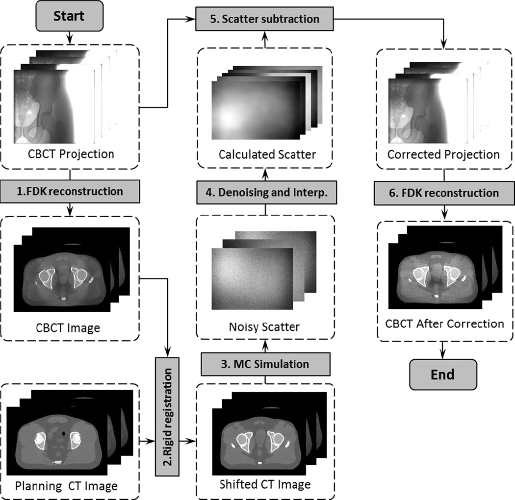
Figure 1 shows the workflow of our method, which consists of six steps. The first step uses an FDK algorithm (Feldkamp et al., 1984) to reconstruct a scatter-contaminated CBCT image directly using raw projections. After that, the second step rigidly registers the planning CT to match the CBCT, which is then used in the MC simulation step to generate noisy scatter signals at a few sparsely placed projection angles. Scatter denoising and interpolation are performed in the next step to yield calculated scatter data at all projection angles. Finally, the calculated scatter data is subtracted from the measured projections. The FDK reconstruction is performed again using the corrected projections to obtain the CBCT image with reduced scatter artifacts.
Figure 1.
Work flow of the CBCT scatter correction process with MC simulations. Shaded boxes are key operations, whereas dashed boxes are data sets in this process.
In the rest of this section, we will first discuss the rationale of using the planning CT data for MC scatter estimations, as opposed to using a scatter-contaminated CBCT. We will then present our techniques to achieve the fast scatter estimations.
2.1 MC-based scatter calculations using a planning CT
In IGRT, a planning CT is always available for treatment planning purposes. Using the planning CT to help scatter estimation has several advantages compared with the method using a scatter-contaminated CBCT image. First, the planning CT image has superior image quality to the CBCT, ensuring more accurate MC modeling and therefore improved calculation accuracy. It has been demonstrated that calculated scatter is inaccurate when using a scatter-contaminated CBCT due to the incorrect HU values (Poludniowski et al., 2009). We also computed scatter signal via MC simulation using a scatter-contaminated CBCT and using a planning CT. The planning CT was deformed to the CBCT to ensure they have the same geometry. It was found that the average differences of the scatter signal magnitude were 18.2% and 29.6% for a full-fan headneck case and a half-fan prostate case, respectively. The average differences of SPR were 2.8% and 13.5% for these two cases. The difference was calculated as |ACT − ACBCT|/ACT pixelwise and then averaged over the entire projection plane, where ACT and ACBCT were scatter signal or SPR calculated using the CT and the CBCT, respectively. Hence, additional strategies have to be employed to handle this issue. For instance, it has been proposed to segment the CBCT image and reassign the HU values before MC simulation (Sisniega et al., 2011). However, the resulting scatter estimation accuracy may still be limited by the uncertainty in those steps. Iterative approaches have also been utilized where several rounds of scatter estimations and correction are performed, aiming at gradually improving the estimation accuracy. There is, nonetheless, no theoretical justification for the convergence of this procedure. The computational cost is also increased accordingly.
The second advantage of using a planning CT is to avoid calculation error caused by the problem of image truncation. CBCT has a relatively small field of view. Laterally truncated CBCT images are frequently seen in IGRT, for instance when a large patient is scanned or when the isocenter is purposely placed very laterally in a patient. While this is typically not a problem for patient setup in IGRT, it significantly impairs MC simulation accuracy due to the missing anatomy in the truncated region. We have actually performed an MC simulation to study this effect. In a relatively large lung cancer patient, the isocenter was placed at the tumor center in the right lung. As a consequence, tissue of about ~3cm thickness on the left side of the patient was outside the field of view. Calculated scatter signals using the full body and the truncated body differed on average by 28% along the lateral projection direction. Another problem associated with the truncation issue is image artifacts within the field of view, which further deteriorate simulation accuracy. Furthermore, CBCT also has a short longitudinal coverage compared to CT (Yan et al., 2014), and this similarly introduces calculation error.
The proposed use of CT for scatter calculations also has its limitations. Rigid registration has been employed to place the planning CT to a correct spatial location for MC simulations. Theoretically speaking, deformable image registration is needed as the patient anatomy deforms from day to day in a non-rigid fashion. However, CT-to-CBCT deformable image registration is a challenging problem by itself. We simply used rigid registration in the proposed method for the considerations of computational efficiency and algorithm robustness. It is hoped that small deformable anatomy variations do not greatly impact the scatter estimation accuracy and hence rigid registration can still provide sufficient accuracy in scatter estimations. This issue will be further discussed in Section 4.
2.2 Techniques for fast scatter estimation
The proposed method involves two FDK reconstruction steps, one MC simulation step, and several other steps. Computations for all of these steps must be substantially accelerated to control the total time into an acceptable level. As such, all of the steps were implemented on one GPU card, which has been demonstrated to be effective for improving computational efficiency (Pratx and Xing, 2011; Jia et al., 2014). In addition, we also employed a few other techniques to speed up the whole process to meet our goal of ~30 sec total computation time. This ensures the practicality of our method, as it currently takes approximately 30 sec in the clinic to reconstruct a CBCT after a scan is completed.
2.2.1 GPU-based computation
In our computations, there were three main components implemented on GPU. The first one was FDK-based CBCT reconstruction (Feldkamp et al., 1984). There have been a number of publications reporting GPU implementations of this algorithm (Li et al., 2007; Sharp et al., 2007; Yan et al., 2008; Noel et al., 2010; Okitsu et al., 2010). Here, we used our in-house developed one. There were three main steps in this algorithm. 1) Reweighting projection data. This step processed each projection with a geometry filter in the FDK algorithm: Parker’s filter for full-fan scan cases (Naparstek, 1980; Parker, 1982; Wesarg et al., 2002), a filter to compensate redundant data in half-fan scan cases (Cho et al., 1995; Cho et al., 1996; Wang, 2002), and a low-pass filter to suppress noise. The computations were performed using one GPU thread for each pixel. 2) Applying a ramp filter. We achieved this step using image space convolution with one GPU thread for the convolution at each pixel. 3) Back-projecting the filtered projections to the image volume. This was computed by letting each GPU thread compute a voxel value. Note that 2D interpolation was necessary in this step, due to the need of fetching pixel values at the projection points of each voxel. GPU texture memory was used here to take advantages of hardware-enabled interpolations.
The second component was rigid registration. We rigidly registered a moving image I1(x), i.e. the planning CT, with a static image I2(x), i.e. the CBCT, by finding a vector y that maximized an energy function E(y) = ∫ dx I1(x + y)I2(x). This is the convolution of the two images, which can be efficiently computed in the Fourier domain. Specifically, we computed E(y) = ℱ−1[ℱ[I1]ℱ[I2]], where ℱ denotes a Fourier transform operation. In our implementation, a GPU-based fast Fourier transform package CUFFT was used (Podlozhnyuk, 2007). After the convolution operation, we found the location for the maximum value of the resulting data, which specified the shift vector y.
The third component was a GPU-based MC photon transport simulation for scatter calculations. We utilized a previously developed package, gDRR (Jia et al., 2012), in this step. The base materials for MC simulation were bone, tissue, and air. Once a CT image was ready for scatter calculations, each voxel was assigned to a material type by thresholding its CT number. Voxels of the same material can have different densities, which were determined from the CT numbers via a mapping that was calibrated to our CT scanner (Schneider et al., 2000). After that, a number of GPU threads were launched to simultaneously transport a group of photons. Each photon was transported from the x-ray source till it exited the phantom or was absorbed in the phantom. If a scattered photon hit the detector, it was tallied in the corresponding pixel location. gDRR considered physics relative to the kV CBCT energy range, namely Rayleigh scatter, Compton scatter, and photoelectric effect. An effective source model was utilized to generate source photons, which represents the beam by a poly-energetic spectrum and a spatially inhomogeneous particle fluence after the bowtie-filter. Parameters in this model were tuned through a calibration process to yield a good representation of our CBCT source. Detector responses were considered by an energy response curve. The accuracy of photon transport in this package has been previously demonstrated by comparing simulation results with those from EGSnrc, as well as indirectly by comparing computed radiation dose with measurements (Montanari et al., 2014).
2.2.2 Other acceleration strategies
In addition to employing GPU-based acceleration, we have used three techniques to further speed up the computations from the algorithmic side.
Due to the randomness inherent to the MC method, noise exists in the calculated scatter signal. As the signal is expected to be smooth along the spatial dimension, a scatter denoising technique can be utilized. The method we used is an optimization-based approach, which has been proposed in Jia et al. (2012). It solves an optimization problem
| (1) |
where S is the smoothed scatter signal to be estimated and Ŝ is the signal computed by MC simulation. β is a constant that controls the relative weight between the data fidelity term (first term in the objective function) designed for Poisson statistics and the smoothing term (second term) that penalizes the image gradient. A successive over-relaxation algorithm was employed to solve this problem (Golub and van Loan, 1996). The resulting accuracy of the signal S obviously depends on the noise level Ŝ, which is governed by the number of photons used in MC simulations. In practice, it is preferred to use fewer photons for efficiency considerations. In Section 3.1.1, we will study the trade-off between the simulation accuracy and the time cost in detail.
Another technique was to downsample the CT volume data for MC simulation. The rationale behind this technique is that the scatter data is typically a low frequency signal in the spatial dimension, and hence it is expected to be insensitive to the details of anatomical structures in the CT image. As such, we reduced the CT resolution and increased voxel size accordingly to speed up the photon transport simulations. Since the CT voxel size along the superior-inferior direction was already large compared to that in the transverse plane, we only downsampled the transverse plane. In Section 3.1.2, the relationship between accuracy and computation time will be analyzed.
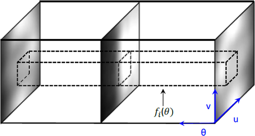
The third technique was to simulate scatter at sparse projection angles, and then interpolate the results to other projection angles. This is motivated by the fact that the scatter signal also varies smoothly along the angular direction. However, it is important to study the variation of the signal along this direction to determine the minimal number of projections needed to maintain the accuracy of the interpolated results. As such, we first accurately computed scatter images for a test pelvis phantom at all projection angles and stacked them to form a 3D volume as shown in Figure 2. We then extracted the pixel intensities for each pixel i at all projection angles θ to form a function fi(θ). Nyquist–Shannon sampling theorem (Jerri, 1977) was utilized on fi(θ) to determine a minimum sampling number Np,i for this pixel, such that a linearly interpolated signal can preserve over 99.9% of the energy. Finally, we took the maximum value of Np,i among all the pixels to determine the number of projections needed Np = maxiNp,i. Again, in Section 3.1.3 we will investigate the trade-off between accuracy and efficiency when the number of projections used in the MC simulation is varied.
Figure 2.
Illustration of minimum projection number analysis for MC simulations.
2.3 Postprocessing
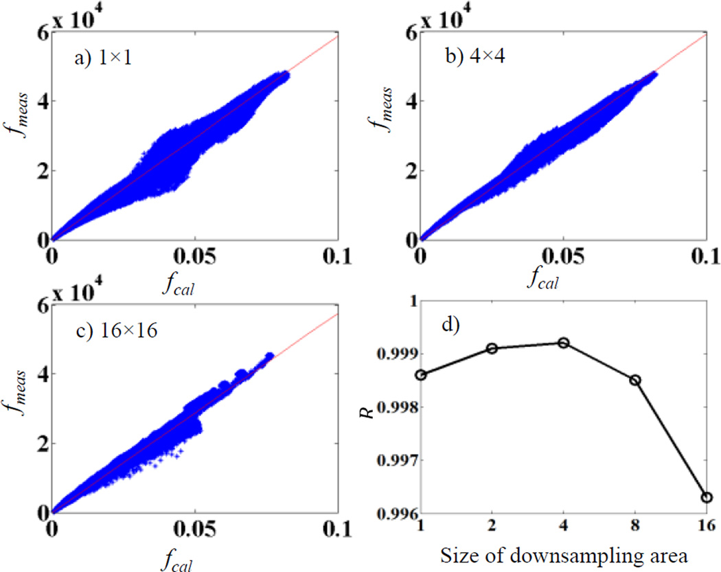
Pixel values from our calculations fcal are in the unit of energy deposited to that pixel per simulated particle, whereas pixel values recorded in a projection file acquired experimentally fmea are in a different unit. It is expected that there exists a calibration factor α, fmea(x, y) = αfcal(x, y). It is important to obtain this factor to convert a calculated scatter image to a scale matching the measurements, so that it can be subtracted from a measured raw projection. For this purpose, we performed the following calibration study. We selected a pelvis phantom and measured its CBCT projections fmea at all projection angles. We also performed MC simulations to get the calculated projections fcal at the same projection angles with 109 photons per projection. Note that in this calibration study, fcal contained both primary and scatter signals. Each projection was downsampled by averaging pixel values in square areas of 4 × 4 pixels, yielding fmea(i, j) and fcal (i, j), where (i, j) are pixel location indices. After that, fmea(i, j) was plotted versus fcal (i, j) and a linear fitting was performed to determine the slope α.
We remark that the downsampling step is actually important. This is because there may be a spatial misalignment between the measured and the calculated projections. Hence linear fitting using the original images would cause error. Figure 3a)–c) plot fmea vs fcal for cases with different sizes of the downsampling area. For cases without downsampling in a), the spatial misalignment leads to a poor linear relationship between fmea and fcal. The linearity is improved with increased downsampling area size. However, at cases with a too large size, averaging over many pixels also compromises the fitting. To demonstrate this effect, we plot R value of the linear fitting in Figure 3d), which peaks at 4. Hence we pick the size of 4 × 4 pixels in our study.
Figure 3.
a)–c) Relationship between fmea and fcal for downsampling with an area of 1 × 1 (no downsampling), 4 × 4, and 16 × 16 pixels. c) R value for the linear fitting.
It is expected that such a calibration factor α depends on specific parameters in each CBCT scan protocol, e.g. mAs. We therefore performed the calibration for each scan protocol. Once this factor was determined through this calibration step, in the scatter calculation and removal experiments, we used them to scale the calculated scatter signals to the proper physical scale.
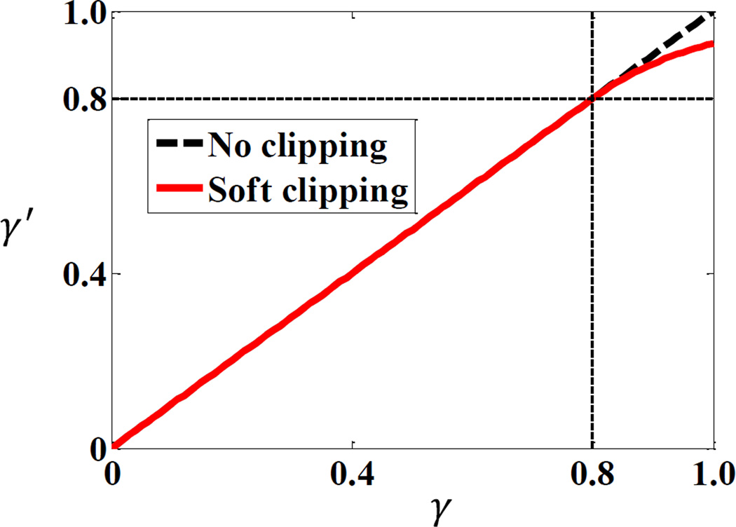
Another postprocessing step is to adjust the calculated scatter signal intensity based on scatter-to-total ratio (STR). At some pixels, the calculated scatter signal may be even larger than the value acquired by the image detector due to calculation errors. Simply subtracting the calculated signal would lead to negative, hence unphysical results. In order to avoid this issue, we employed a method to clip the maximum level of STR (Zhu et al., 2006; Sun and Star-Lack, 2010). Specifically, the STR γ at each pixel was first calculated by taking the quotient of the MC-calculated scatter signal and the measured total signal p0. A new STR level γ′(γ) was calculated based on this γ value via a function proposed by Zhu et al. (2006) to avoid unphysical results of γ > 1. Finally, the primary signal was estimated as p = p0(1 − γ′(γ)). The function form γ′(γ) is
| (2) |
where the parameter β = 0.8 was chosen empirically for all our tested cases. The function form γ′(γ) is shown in Figure 4. As γ → ∞, γ′ approaches unity.
Figure 4.
Function form for the clipping function of STR in scatter subtraction.
2.4 Evaluation
To evaluate our method, we performed the following studies. First, simulation studies in both full-fan and half-fan cases were conducted. As ground truth images were known in these simulation cases, we were able to study the impact of different parameters in our method, i.e. downsampling factor, photon history number, and number of projections, on the resulting scatter estimation accuracy and computational efficiency. This established the appropriate parameter values. For each of the simulation cases, two CT images for a patient were used, which were acquired at two different fractions during a treatment course. The resolution of each CT image dataset was 512 × 512 × 100 with a voxel size of 0.98 × 0.98 × 2.5 mm. To generate scatter-contaminated CBCT projections, we conducted MC simulations using gDRR (Jia et al., 2012) on the first CT image. The second CT image was utilized as the planning CT needed for our scatter estimation method. In those simulation cases, the relative scatter estimation error, E, was calculated as E = |Se − Sr|/|Sr|, where Se and Sr are vectors for the estimated scatter and the ground truth, respectively. |·| denotes standard L2 norm of a vector.
We then evaluated the performance of our method using an anthropomorphic male pelvic phantom (CIRS Inc., Norfolk, VA, USA). The phantom was first scanned in a Philips 16-slice Brilliance large-bore simulator (Philips Healthcare Inc, Cleveland OH). A CBCT scan was then performed with a Varian TrueBeam On-Board Imaging (OBI) system (Varian Medical System Inc. Palo Alto, CA). Six hundred and fifty nine projections were acquired under a pelvis scan protocol of 125 kVp and 1.6 mAs/projection in the half-fan mode. In addition to visually comparing CBCTs with and without scatter removal, we also utilized spatial nonuniformity (SNU) to characterize the improvement of image quality (Mail et al., 2009; Niu et al., 2012). Specifically, six ROIs that should have the same image intensity were selected and was calculated, where and were the maximum and the minimum of the mean CT numbers among these ROIs, respectively.
Finally, we validated our method in a head and neck (HN) cancer patient case and a prostate cancer patient case. For the HN case, 364 projections were acquired in the TrueBeam OBI system under a full-fan scan protocol with 100kVp and 0.4 mAS. For the prostate case, 656 projections were acquired with 120kVp and 1.6mAs under a half-fan protocol. Planning CT images for both cases were taken from a Philips 16-slice Brilliance large-bore 4-D CT simulator. The image resolutions were 512 × 512 × 100 with a voxel size of 0.98 × 0.98 × 2.5 mm.
3. RESULTS
3.1 Impact of parameters
We first investigated the impact of three parameters in our method on the resulting accuracy and computational efficiency. Studies were conducted in simulation cases where ground truth was known. The purpose of this step was to establish a practical set of parameters under which we could accomplish the whole scatter estimation and CBCT reconstruction process in ~30 sec while not compromising accuracy.
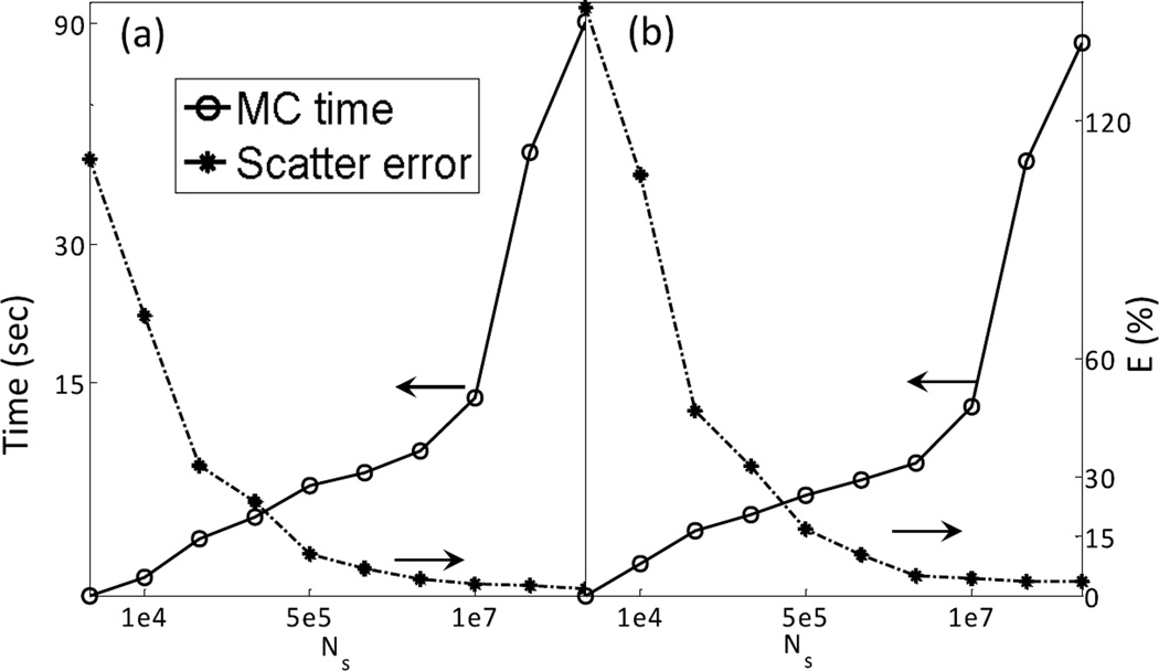
The three parameters we tuned were the number of photon histories per projection in MC simulation Ns, the factor to downsample the CT volume Nd, and the number of projections for which scatter is simulated Np. As stated in Sec 2.2.2, we downsample each transverse CT slice to improve photon transport efficiency. The downsampling factor Nd is defined to be the ratio of the new voxel size in the transverse slice to the original voxel size. Theoretically speaking, studies extending the entire domain of (Ns, Nd, Np) could be performed to explore all possible combinations of these parameters in order to select the optimal one . Yet this would be a tedious process, and presenting the variations of accuracy and efficiency in this three dimensional space would probably add little value to the demonstration of the validity of our method. In addition, it is expected that, strictly speaking, the exact number is case dependent. Hence, performing detailed investigations for a particular case is probably not important. Due to these considerations, our purpose was rather to establish a parameter set that could serve as a guideline for practical utilization of our method. As such, we first found an acceptable parameter set through a trial and error process in the entire three-dimensional parameter space. In each of the following three subsections, we will fix two of them to the acceptable parameter values and demonstrate the trade-off between accuracy and efficiency, while the third one is tuned. When evaluating the accuracy, we considered the ground truth as simulation results with 109 photons per projection with the denoising algorithm applied. Relative error E = |Se − Sr|/|Sr| was used to quantify the accuracy with Se and Sr denoting the estimated scatter and the ground truth, respectively. As for the efficiency evaluation, total computation time was used.
3.1.1 Photon history number
The number of photon histories per projection used in an MC simulation Ns can obviously impact both accuracy and efficiency. While it is possible to reduce computation time by using fewer photons, the resulting scatter signal becomes noisier, causing increased error. Figure 5 demonstrates this trade-off. Here we fix and vary Ns. The error is calculated on the denoised scatter signal, which is simulated at projection angles and then interpolated to all the angular directions. The computation time reported here is for the MC simulation step only. From this figure, it is clear that beyond 107 photons per projection, further increasing the number of photons does not significantly improve accuracy anymore. With this photon number, the computation time is within 15 sec. Since we would like to keep the total computation time within ~30 sec, and we found that the total time for FDK reconstructions and other steps is ~15 sec, MC simulation time is restricted to ~15 sec. Therefore, was selected.
Figure 5.
Scatter estimation error and computation time as a function of photon histories number for (a) full-fan and (b) half-fan cases.
3.1.2 Downsampling factor
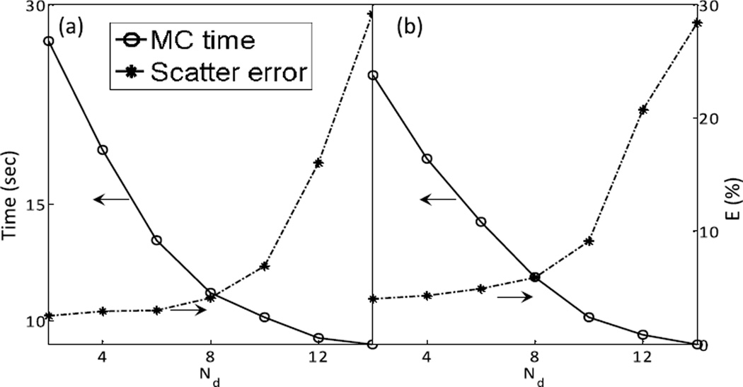
By downsampling the phantom volume, the photon transport can be sped up. Figure 6 depicts the computation time and accuracy of the resulting scatter signal as functions of the factor Nd used when downsampling the CT volume with fixed . As Nd increases, the computation error initially increases slowly. It then increases sharply when Nd becomes relatively large. In order to maintain simulation accuracy and keep the computation time to within the goal of ~15 sec, we chose in our method.
Figure 6.
Scatter estimation error and computation time as a function of downsampling times for (a) full-fan and (b) half-fan cases.
3.1.3 Number of views
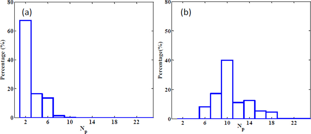
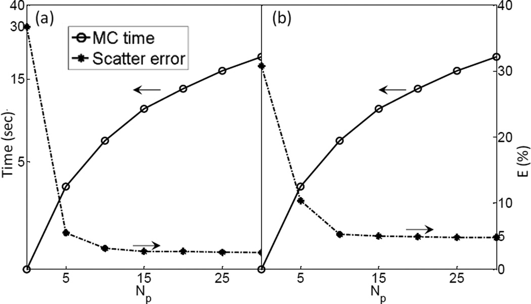
As mentioned in Section 2.2, in order to figure out the minimum number of projections needed to restore the completed scatter signal via interpolation, we performed Fourier analysis on each fi(θ), the variation of the scatter signal at a pixel i along the angular direction. Then the minimal number of views Np,i for this pixel was derived by Nyquist–Shannon sampling theorem, such that a linearly interpolated signal can preserve over 99.9% of the energy. Figure 7 shows the histogram of Np,i. It indicates that 10 views for the full-fan case and 20 views for the half-fan case are sufficient. We have also analyzed the trade-off between the accuracy and simulation time with , as shown in Figure 8. When the simulated projection number becomes larger than 15, further increasing this parameter value does not help reduce the error significantly anymore. Meanwhile, the MC simulation time is under 15 sec, as long as the view number is less than 20. Hence, we chose .
Figure 7.
Histogram of minimum number of views to yield sufficient accuracy after interpolation for (a) full-fan and (b) half-fan cases.
Figure 8.
Scatter estimation error and computation time as a function of view number for (a) full-fan and (b) half-fan cases.
3.2 Image quality
3.2.1 Simulation studies
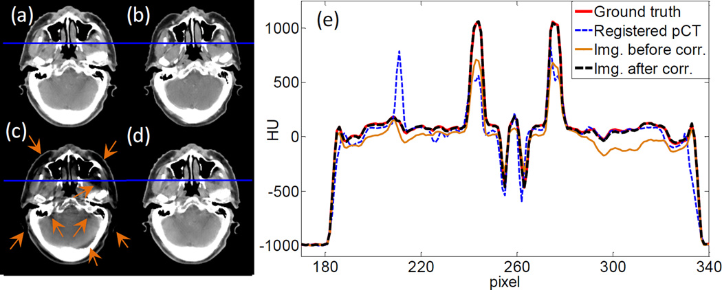
With the parameter settings determined, we move on to demonstrate the efficacy of our method in terms of image quality. Figure 9(a)–(d) are the ground truth image, the rigidly registered planning CT image, and the images before and after scatter correction in the full-fan simulation study, respectively. Compared with the uncorrected image, the one after scatter correction has much reduced scatter artifacts as indicated by the arrows. The overall HU accuracy is also improved. We have also plotted line profiles along a horizontal cut in Figure 9(e). It is clear that after scatter correction, the image intensity agrees with the ground truth much better than the uncorrected one.
Figure 9.
(a) Ground truth image. (b) Registered planning CT image. (c) CBCT before scatter correction. (d) CBCT after scatter correction. Display window [−125, 225] HU. (e) Profiles on the blue line in (a)~(d).
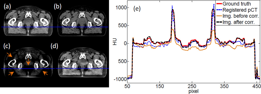
Figure 10 shows the results of the half-fan simulation study. Again, much improved image quality is observed after the scatter correction step. In particular, the bowtie filter artifacts are removed well, as indicated by the arrows. This bowtie filter artifact is due to the coupling between x-ray projection error and the air norm intensity after the bowtie filter. Suppose the x-ray air norm after the bowtie filter is Io. After the x-ray travels through an object, its intensity becomes Ioe−l, where l is the path integral of x-ray attenuation coefficient, which is needed in reconstruction. However, the detector receives a signal Ioe−l + s. Here s denotes a general error term with scatter being its main component. In the log transform prior to reconstruction, the transformed data becomes to the leading order of s. This implies that the error term after this log transformation has a leading component of sel/Io which is modulated by the air norm Io. Due to the bowtie filter design, Io is large in the center of the detector and small on the sides. This leads to spatially varying error in the transformed data, relatively small in the center and large on the peripheral region. After reconstruction, it will cause different amount of image error between the image center and its periphery. The transition between them appears as the bowtie artifact.
Figure 10.
(a) Ground truth image. (b) Registered planning CT image. (c) CBCT before scatter correction. (d) CBCT after scatter correction. Display window [−125, 225] HU. (e) Profiles on the blue line in (a)~(d).
To quantitatively evaluate the improvements in image quality, we have computed maximum error emax, 95th percentile error e95%, and mean error ē for the CBCT images before and after scatter correction. The results are summarized in Table 1. The proposed scatter correction method reduces the mean error from 44 HU to 3 HU and from 78 HU to 9 HU for the full-fan and the half-fan cases, respectively. Maximum error is reduced from 456 to 37 HU and from 584 to 128 HU for the two cases, respectively.
Table 1.
Errors of HU value before/after scatter correction for the simulation studies.
| emax (HU) | e95% (HU) | ē (HU) | |
|---|---|---|---|
| Full-fan | 456/37 | 136/10 | 44/3 |
| Half-fan | 584/128 | 386/34 | 78/9 |
3.2.2 Phantom and patient studies
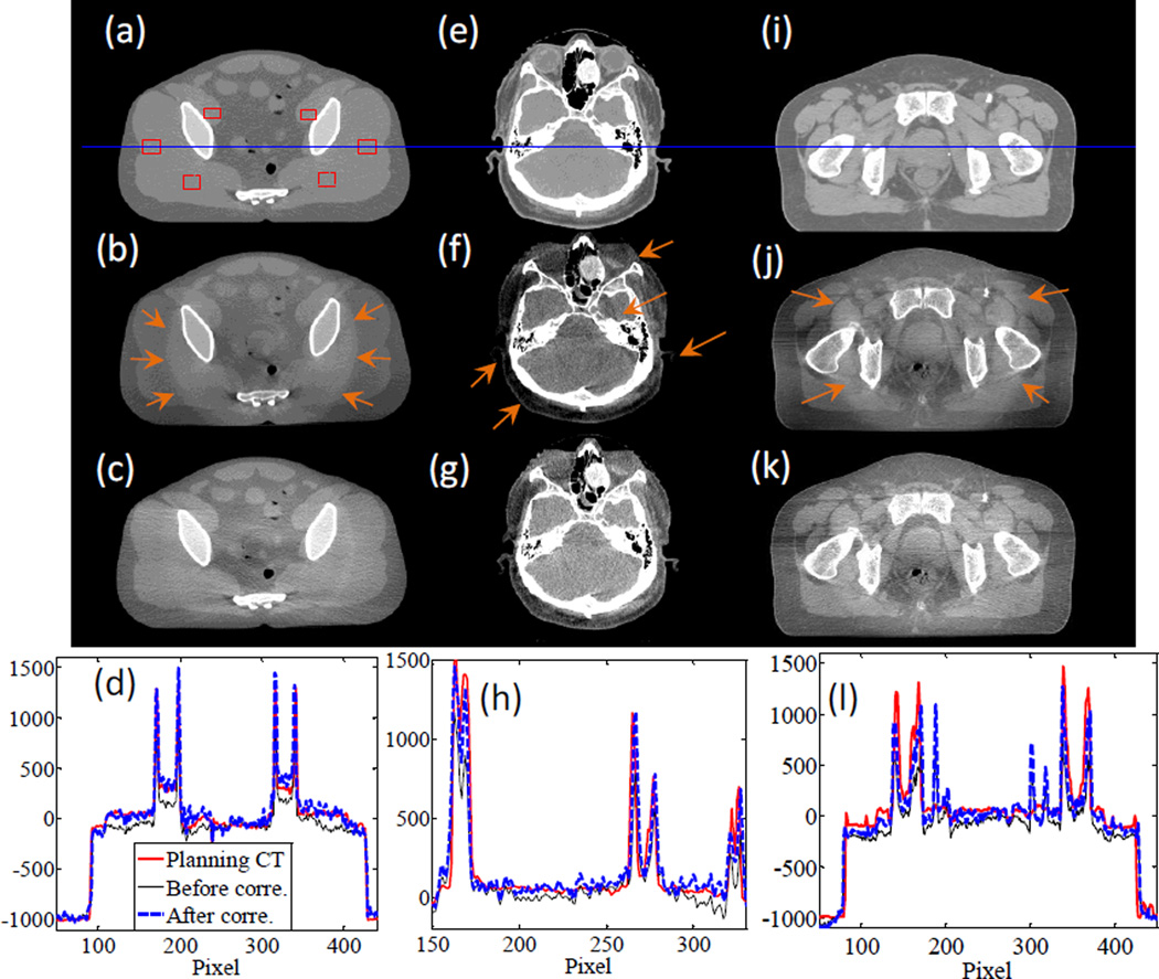
In Figure 11, we present the results for the pelvis phantom experiment and the two patient cases. For the pelvis phantom case, one of the obvious improvements in image quality is the reduction of the bowtie filter artifacts, as indicated by the arrows in Figure 11(b). The overall image intensity has also been corrected, and is in better agreement with the CT image, as indicated by the comparisons in image profiles. We have computed the SNU index using the six selected rectangular areas drawn in Figure 11(a). The SNU values for the CT and CBCT images before and after scatter correction are 0.7%, 12.1%, and 4.5%, respectively, indicating an improved HU value accuracy after scatter correction.
Figure 11.
From top to bottom: planning CT image, CBCT image before scatter correction, CBCT image after scatter correction, and profiles along the horizontal line in the first row. The three columns are for pelvis phantom experiment, full-fan clinical case, and half-fan clinical case, respectively. Display windows are [−500, 500] HU, [−300, 300] HU, and [−400, 300] HU for the three columns.
For the patient cases we have also observed improvements in image quality. Specifically, in the HN case scanned in the full-fan mode, image intensity accuracy at the periphery region is improved, and the scatter artifacts indicated by the arrows are largely reduced. For the half-fan prostate cancer patient case, the scatter correction step reduces the ring artifact caused by the bowtie filter. The overall intensity value is also corrected.
3.3 Computational efficiency
Table 2 summarizes the computational time for each step, as well as the total computation time. All the computations were performed on one NVIDIA Titan black GPU card. As expected, the most time-consuming step is MC scatter simulation. Under the parameter settings determined in Section 3.1, the time in this step is below 15 sec for all the cases. The time for the FDK reconstruction step primarily depends on the scan mode. The half-fan cases are slower than the full-fan cases, which is ascribed to the larger number of projections. The computational time for the registration and projection processing steps remains constant among all cases. With all the techniques employed, we have successfully reduced the computation time to within 30 sec, including two FDK reconstructions, one MC-based scatter estimation, and other necessary steps.
Table 2.
Computation time in different cases.
| Case | Step 1 FDK (sec) |
Step 2 Registration (sec) |
Step 3 MC Simu. (sec) |
Step 4, 5 Prj. Proc. (sec) |
Step 6 FDK (sec) |
Total (sec) |
|
|---|---|---|---|---|---|---|---|
| Simulation | Full-fan | 2.37 | 0.66 | 13.89 | 0.28 | 2.24 | 19.44 |
| Half-fan | 7.30 | 0.62 | 13.49 | 0.28 | 7.10 | 28.79 | |
| Clinical | Full-fan | 2.35 | 0.66 | 13.92 | 0.25 | 2.23 | 19.41 |
| Half-fan | 7.35 | 0.66 | 13.89 | 0.29 | 7.19 | 29.38 | |
| Phantom | Half-fan | 7.26 | 0.60 | 14.04 | 0.24 | 7.15 | 29.29 |
4. CONCLUSIONS AND DISCUSSION
In this paper, we have presented our recent development of a practical MC-based scatter estimation and removal method for CBCT. A patient planning CT image was used for MC simulation because of the advantages of accurate image intensity and absence of image truncation. A scatter calculation and removal workflow was developed, which was implemented on a GPU platform for high computational efficiency. The impact of three key parameters in the MC simulation step was studied to determine an optimal parameter set, under which the computation time was reduced to a clinically acceptable level without compromising accuracy. We studied the performance of our method in simulation, phantom, and patient cases. In the simulation cases our method reduced the mean HU error from 44 HU to 3 HU and from 78 HU to 9 HU for the full-fan and the half-fan cases, respectively. In both the phantom and the patient cases, improved overall accuracy of image intensity was observed. CBCT image artifacts caused by scatter, such as ring artifacts around the bowtie area, were reduced. With all the computational techniques, we were able to achieve computation time of less than 30 sec including the time for both scatter estimation and CBCT reconstruction steps. This makes the developed method practical for clinical use.
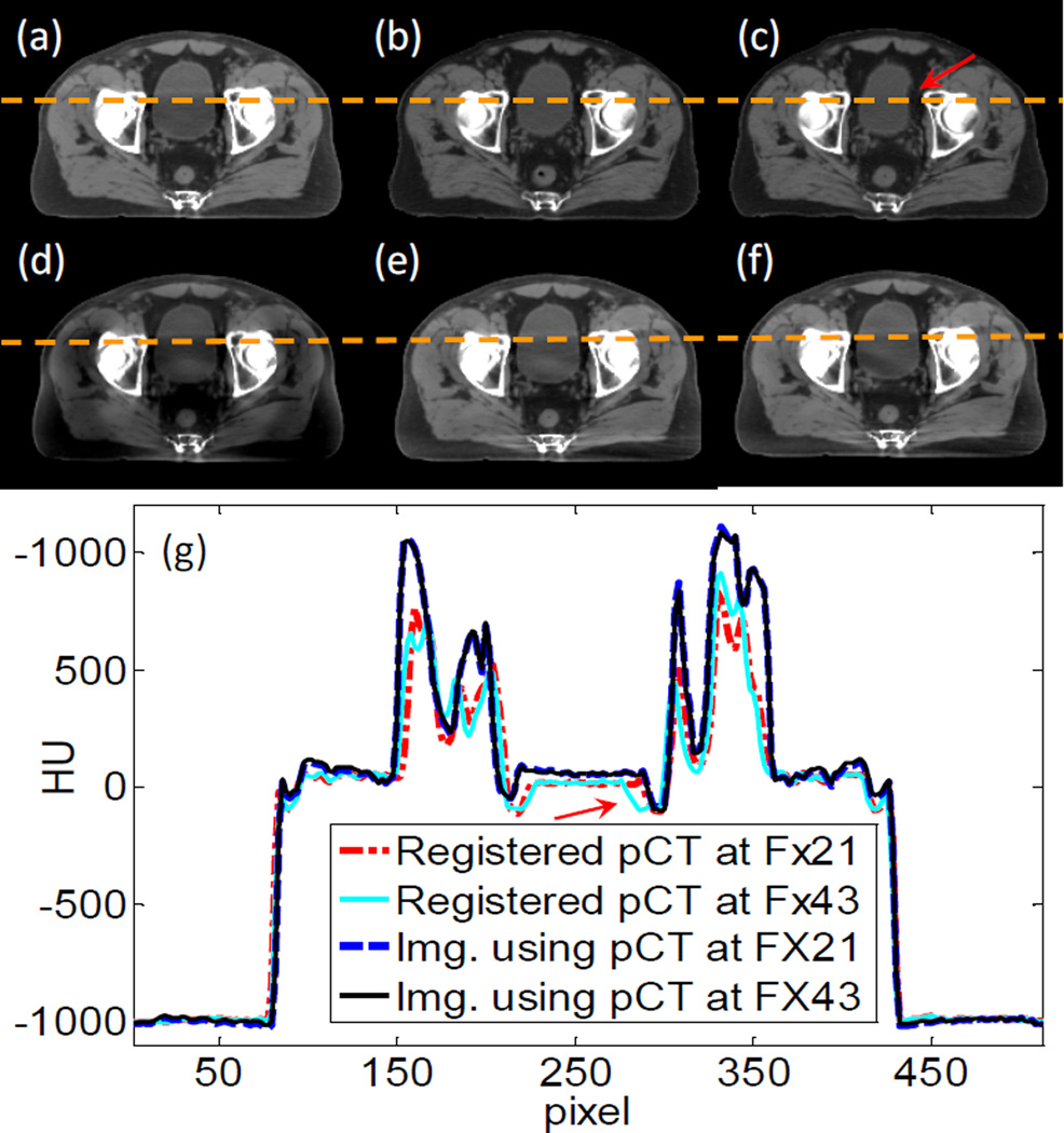
There are a few issues that we would like to discuss. First, one of the contributions of this work is to propose the use of a planning CT for MC-based scatter estimation. Although deformable image registration is needed theoretically to exactly match the planning CT with the CBCT, rigid registration was utilized for considerations of simplicity and robustness. The assumption is that scatter signal is not sensitive to small anatomy variations. Here, we validate this assumption via a simulation study using a prostate cancer patient who has three CT images acquired at the planning stage, at fraction (Fx) 21, and at Fx 43 as shown in Figure 12(a)–(c). We first computed scatter-contaminated CBCT projections for the patient anatomy in the planning CT using MC simulation. If the scatter was left uncorrected, the reconstructed CBCT would be degraded as shown in Figure 12(d). We conducted two scatter removal studies with our method using the CTs at Fx 21 and Fx 43 as prior CT images. Figure 12(e) and (f) are images after correction using the two different CTs. The anatomy deformation is relatively small between the planning stage and Fx 21. The scatter correction yields much improved image quality with reduced artifacts. At Fx 43 the deformations become large, especially in the bladder area as indicated by the arrow. However, the efficacy on scatter correction is still satisfactory. The corrected image in Figure 12(f) is almost the same as in (e), except for some residual artifacts in the bladder area. Hence, although our assumption is only valid to a certain degree, we think the impact of deformation on the resulting scatter estimation is small and acceptable in practice.
Figure 12.
(a)–(c) Three CT images taken at planning, Fx 21, and Fx 43. (d) CBCT image before scatter correction. (e) CBCT image after scatter correction with CT at Fx 21. (f) CBCT image after scatter correction with CT at Fx 43. Display window [−125 225] HU. (g) Profiles on the dash line in the image.
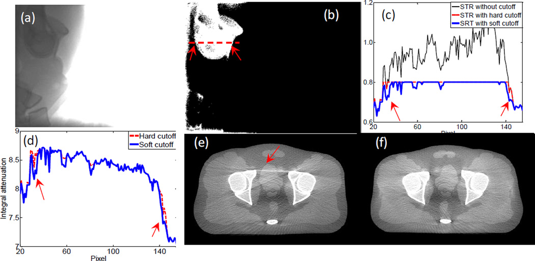
Another issue that affects scatter estimation accuracy is the way of imposing STR cutoff. There are two STR clamping methods reported in literature, namely a hard-cutoff method (Sun and Star-Lack, 2010) and a soft-cutoff method (Zhu et al., 2006). We found that the soft-cutoff method yields better image quality. For instance, Figure 3(a) is a measured projection for the pelvis phantom case along a lateral projection direction. The pixel values behind the bony structures, especially the femoral heads, are substantially lower than those in other areas such as behind soft tissue. Hence, the STR behind the bony structures is relatively high. In Figure 3(b), we show a Boolean image of STR value where the value is unity when STR is over 0.8 and zero otherwise. Figure 3(c) plots STR profile along the dashed line in (b). Not only is the STR high in this area, it is even over unity at some pixels due to inaccurately estimated scatter signals. Hence, a threshold is needed to avoid unphysical results. The resulting STRs after the two cutoff methods, as well as the corresponding primary signals, are shown in Figure 3(c) and (d), respectively. Because of the absence of ground truth, it is difficult to justify which estimated primary signal is more accurate. However, after CBCT image reconstruction, the one with the soft cutoff method has much fewer streak artifacts. This can probably be ascribed to the slightly different transition from the bone to the tissue region in the estimated primary signal, as indicated by the arrows in (d). In fact, the total signal changes dramatically when crossing the boundary of this bony structure region. If a constant STR cutoff were used, a sharp jump would appear in the estimated scatter. This is probably incorrect, because the scatter signal slowly varies along the spatial direction.
Rigid registration with only translation was used in our study due to its high efficiency. However, it should include rotational degrees of freedom in general. To investigate the necessity of rotations, we have compared scatter calculation results under rigid registrations with and without rotations. The rigid registration with rotations was achieved using 3D Slicer (version 4.2.2-1)(Fedorov et al., 2012). Average difference for calculated scatter signals was quite small, ~0.2% for all our tested cases. The impacts on corrected CBCT images were negligible. This is because the patient CBCT was acquired after the patient was carefully set up prior to a radiotherapy treatment and rotation was usually quite small. Regarding computation time with rotation degrees of freedom, it was ~10 sec longer. This prolonged the whole process of our method. However, we also noticed that recent advances in GPU computing shorten the computation time to ~1.5 s (Ledig and Chefdhotel, 2010). In summary, although rigid registration with rotational degrees of freedom is probably not needed for radiotherapy, it may be necessary for general applications. In that case, we can implement the advanced rigid-registration tool to maintain both accuracy and efficiency.
We would also like to point out that, at present, standard clinical scatter estimation and removal methods are already capable of eliminating scatter artifacts to a satisfactory degree in most cases. For instance, high-quality CBCT images can be produced in the OBI system of the Varian TrueBeam linear accelerator. Yet, in some challenging situations, e.g. the lung area, the efficacy of the clinical standard method is still limited, primarily due to the highly heterogeneous structure, which is quite different from the setup, under which this method was derived (Sun and Star-Lack, 2010). We show in Figure 14 a lung patient case in our clinic. After scatter correction by the commercial system, the overall image intensity accuracy is improved. However, obvious streaks and residue artifacts still exist. With our method, we are able to eliminate some of the streak artifacts and obtain improved image quality. There are still some dark areas in the image due to the residual scatter signal. Note that there are some other artifacts in the image, e.g. streaks, which are actually caused by respiratory motion. These artifacts cannot be addressed through a scatter correction process.
Figure 14.
(a) Reconstructed image without scatter correction. (b) CBCT reconstructed by the OBI system in Varian TrueBeam. (c) CBCT reconstructed by our proposed method. Display window [−300 300] HU.
It is also noted that noise is amplified in the projection images after scatter correction, resulting in an increased noise level in the projection domain and in the reconstructed image domain (Zhu et al., 2009a). Hence, a certain type of denoising algorithm is needed. Projection image denoising is another important topic, and there have been a lot of algorithms developed in the community. In this study, we did not implement a noise reduction method, as it is beyond the scope of this manuscript. However, such a step is necessary for routine clinical application.
Figure 13.
(a) A measured projection image. (b) A Boolean image showing STR>0.8 (white) or STR<0.8 (black). (c) Profile of STR along the dash line in (b). (d) Corrected primary signal along the dash line. (e) CBCT image after scatter correction with hard cutoff mapping. (f) CBCT image after scatter correction with soft cutoff mapping. Display window [−500 500] HU.
Acknowledgement
This work is supported in part by NIH (1R01CA154747-01, 1R21CA178787-01A1, 1R21EB017978-01A1), American Cancer Society (RSG-13-326-01-CCE), National Natural Science Foundation of China (81301940, 81428019), and Guangdong Strategic Emerging Industry Core Technology Research (2011A081402003). The authors would like to thank Ms. Dee Hill for proofreading the manuscript.
References
- Badal A, Badano A. Accelerating Monte Carlo simulations of photon transport in a voxelized geometry using a massively parallel graphics processing unit. Medical Physics. 2009;36:4878–4880. doi: 10.1118/1.3231824. [DOI] [PubMed] [Google Scholar]
- Bani-Hashemi A, Blanz E, Maltz J, Hristov D, et al. TU - D - I - 611 - 08: Cone Beam X - Ray Scatter Removal Via Image Frequency Modulation and Filtering. Medical Physics. 2005;32:2093. doi: 10.1109/IEMBS.2005.1616811. [DOI] [PubMed] [Google Scholar]
- Cai W, Ning R, Conover D. Simplified method of scatter correction using a beam-stop-array algorithm for cone-beam computed tomography breast imaging. Opt Eng. 2008;47:097003–097010. [Google Scholar]
- Cho PS, Johnson RH, Griffin TW. Cone-beam CT for radiotherapy applications. Physics in medicine and biology. 1995;40:1863. doi: 10.1088/0031-9155/40/11/007. [DOI] [PubMed] [Google Scholar]
- Cho PS, Rudd AD, Johnson RH. Cone-beam CT from width-truncated projections. Computerized medical imaging and graphics. 1996;20:49–57. doi: 10.1016/0895-6111(96)00031-6. [DOI] [PubMed] [Google Scholar]
- Colijn A-P, Beekman FJ. Accelerated simulation of cone beam X-ray scatter projections. Medical Imaging, IEEE Transactions on. 2004;23:584–590. doi: 10.1109/tmi.2004.825600. [DOI] [PubMed] [Google Scholar]
- Endo M, Tsunoo T, Nakamori N, Yoshida K. Effect of scattered radiation on image noise in cone beam CT. Med Phys. 2001;28:469–474. doi: 10.1118/1.1357457. [DOI] [PubMed] [Google Scholar]
- Fedorov A, Beichel R, Kalpathy-Cramer J, Finet J, et al. 3D Slicer as an Image Computing Platform for the Quantitative Imaging Network. Magn Reson Imaging. 2012;30(9):1323–1341. doi: 10.1016/j.mri.2012.05.001. http://www.slicer.org. [DOI] [PMC free article] [PubMed] [Google Scholar]
- Feldkamp LA, Davis LC, Kress JW. Practical cone beam algorithm. Journal of the Optical Society of America A-Optics Image Science and Vision. 1984;1:612–619. [Google Scholar]
- Gao H, Zhu L, Fahrig R. Modulator design for x-ray scatter correction using primary modulation: Material selection. Med Phys. 2010;37:4029–4037. doi: 10.1118/1.3457472. [DOI] [PMC free article] [PubMed] [Google Scholar]
- Golub GH, van Loan CF. Matrix computation. JHU Press; 1996. [Google Scholar]
- Hangartner TN. Correction of scatter in computed tomography images of bone. Medical physics. 1987;14:335–340. doi: 10.1118/1.596089. [DOI] [PubMed] [Google Scholar]
- Jaffray DA, Drake DG, Moreau M, Martinez AA, et al. A radiographic and tomographic imaging system integrated into a medical linear accelerator for localization of bone and soft-tissue targets. International Journal of Radiation Oncology* Biology* Physics. 1999;45:773–789. doi: 10.1016/s0360-3016(99)00118-2. [DOI] [PubMed] [Google Scholar]
- Jaffray DA, Siewerdsen JH, Wong JW, Martinez AA. Flat-panel cone-beam computed tomography for image-guided radiation therapy. International Journal of Radiation Oncology* Biology* Physics. 2002;53:1337–1349. doi: 10.1016/s0360-3016(02)02884-5. [DOI] [PubMed] [Google Scholar]
- Jarry G, Graham SA, Moseley DJ, Jaffray DJ, et al. Characterization of scattered radiation in kV CBCT images using Monte Carlo simulations. Med Phys. 2006;33:4320–4329. doi: 10.1118/1.2358324. [DOI] [PubMed] [Google Scholar]
- Jerri AJ. The Shannon sampling theorem—Its various extensions and applications: A tutorial review. Proceedings of the IEEE. 1977;65:1565–1596. [Google Scholar]
- Jia X, Yan H, Cerviño L, Folkerts M, et al. A GPU tool for efficient, accurate, and realistic simulation of cone beam CT projections. Medical physics. 2012;39:7368–7378. doi: 10.1118/1.4766436. [DOI] [PMC free article] [PubMed] [Google Scholar]
- Jia X, Ziegenhein P, Jiang SB. GPU- based high-performance computing for radiation therapy. Physics in Medicine and Biology. 2014;59:R151. doi: 10.1088/0031-9155/59/4/R151. [DOI] [PMC free article] [PubMed] [Google Scholar]
- Kruger DG, Zink F, Peppler WW, Ergun DL, et al. A regional convolution kernel algorithm for scatter correction in dual - energy images: Comparison to single - kernel algorithms. Medical physics. 1994;21:175–184. doi: 10.1118/1.597297. [DOI] [PubMed] [Google Scholar]
- Kyriakou Y, Riedel T, Kalender WA. Combining deterministic and Monte Carlo calculations for fast estimation of scatter intensities in CT. Physics in medicine and biology. 2006;51:4567. doi: 10.1088/0031-9155/51/18/008. [DOI] [PubMed] [Google Scholar]
- Ledig C, Chefdhotel C. Efficient Computation of Joint Histograms and Normalized Mutual Information on CUDA Compatible Devices. HP-MICCAI. 2010;2010:90–99. [Google Scholar]
- Li M, Yang H, Koizumi K, Kudo H. Fast cone-beam CT reconstruction using CUDA architecture. Medical Imaging Technology. 2007;25:243–250. [Google Scholar]
- Mail N, Moseley D, Siewerdsen J, Jaffray D. The influence of bowtie filtration on cone-beam CT image quality. Medical Physics. 2009;36:22–32. doi: 10.1118/1.3017470. [DOI] [PubMed] [Google Scholar]
- Mainegra-Hing E, Kawrakow I. Variance reduction techniques for fast Monte Carlo CBCT scatter correction calculations. Physics in medicine and biology. 2010;55:4495. doi: 10.1088/0031-9155/55/16/S05. [DOI] [PubMed] [Google Scholar]
- Maltz JS, Blanz W-E, Hristov D, Bani-Hashemi A. Engineering in Medicine and Biology Society, 005. IEEE-EMBS 2005. 27th Annual International Conference of the. IEEE; 2006. Cone beam X-ray scatter removal via image frequency modulation and filtering; pp. 1854–1857. [DOI] [PubMed] [Google Scholar]
- Montanari D, Scolari E, Silvestri C, Graves CYJ, et al. Cone beam CT dose assessments using Monte Carlo simulations. Phys Med Biol. 2014;59:1239. doi: 10.1088/0031-9155/59/5/1239. [DOI] [PubMed] [Google Scholar]
- Naparstek A. Short-Scan Fan-Beam Algorithms for Cr. Nuclear Science, IEEE Transactions on. 1980;27:1112–1120. [Google Scholar]
- Ning R, Tang X, Conover D. X-ray scatter correction algorithm for cone beam CT imaging. Medical physics. 2004;31:1195–1202. doi: 10.1118/1.1711475. [DOI] [PubMed] [Google Scholar]
- Ning R, Tang X, Conover DL. Medical Imaging 2002. International Society for Optics and Photonics; 2002. X-ray scatter suppression algorithm for cone-beam volume CT; pp. 774–781. [Google Scholar]
- Niu T, Al-Basheer A, Zhu L. Quantitative cone-beam CT imaging in radiation therapy using planning CT as a prior: first patient studies. Medical physics. 2012;39:1991–2000. doi: 10.1118/1.3693050. [DOI] [PMC free article] [PubMed] [Google Scholar]
- Niu T, Sun M, Star-Lack J, Gao H, et al. Shading correction for on-board cone-beam CT in radiation therapy using planning MDCT images. Med Phys. 2010;37:5395–5406. doi: 10.1118/1.3483260. [DOI] [PubMed] [Google Scholar]
- Niu T, Zhu L. Scatter correction for full-fan volumetric CT using a stationary beam blocker in a single full scan. Med Phys. 2011;38:6027–6038. doi: 10.1118/1.3651619. [DOI] [PMC free article] [PubMed] [Google Scholar]
- Noel PB, Walczak AM, Xu J, Corso JJ, et al. GPU-based cone beam computed tomography. Computer Methods and Programs in Biomedicine. 2010;98:271–277. doi: 10.1016/j.cmpb.2009.08.006. [DOI] [PubMed] [Google Scholar]
- Ohnesorge B, Flohr T, Klingenbeck-Regn K. Efficient object scatter correction algorithm for third and fourth generation CT scanners. European radiology. 1999;9:563–569. doi: 10.1007/s003300050710. [DOI] [PubMed] [Google Scholar]
- Okitsu Y, Ino F, Hagihara K. High-performance cone beam reconstruction using CUDA compatible GPUs. Parallel Computing. 2010;36:129–141. [Google Scholar]
- Ouyang L, Song K, Wang J. A moving blocker system for cone-beam computed tomography scatter correction. Medical physics. 2013;40:071903. doi: 10.1118/1.4811086. [DOI] [PubMed] [Google Scholar]
- Parker DL. Optimal short scan convolution reconstruction for fan beam CT. Medical Physics. 1982;9:254–257. doi: 10.1118/1.595078. [DOI] [PubMed] [Google Scholar]
- Podlozhnyuk V. FFT-based 2D convolution. NVIDIA white paper. 2007 [Google Scholar]
- Poludniowski G, Evans PM, Hansen VN, Webb S. An efficient Monte Carlo-based algorithm for scatter correction in keV cone-beam CT. Physics in Medicine and Biology. 2009;54:3847–3864. doi: 10.1088/0031-9155/54/12/016. [DOI] [PubMed] [Google Scholar]
- Pratx G, Xing L. GPU computing in medical physics: A review. Medical Physics. 2011;38:2685–2697. doi: 10.1118/1.3578605. [DOI] [PubMed] [Google Scholar]
- Schneider W, Bortfeld T, Schlegel W. Correlation between CT numbers and tissue parameters needed for Monte Carlo simulations of clinical dose distributions. Physics in Medicine and Biology. 2000;45:459–478. doi: 10.1088/0031-9155/45/2/314. [DOI] [PubMed] [Google Scholar]
- Seibert J, Boone J. X - ray scatter removal by deconvolution. Medical physics. 1988;15:567–575. doi: 10.1118/1.596208. [DOI] [PubMed] [Google Scholar]
- Sharp GC, Kandasamy N, Singh H, Folkert M. GPU-based streaming architectures for fast cone-beam CT image reconstruction and demons deformable registration. Physics in Medicine and Biology. 2007;52:5771–5783. doi: 10.1088/0031-9155/52/19/003. [DOI] [PubMed] [Google Scholar]
- Shaw C-G, Ergun DL, Myerowitz P, Van Lysel M, et al. A technique of scatter and glare correction for videodensitometric studies in digital subtraction videoangiography. Radiology. 1982;142:209–213. doi: 10.1148/radiology.142.1.7031761. [DOI] [PubMed] [Google Scholar]
- Siewerdsen JH, Jaffray DA. Cone-beam computed tomography with a flat-panel imager: magnitude and effects of x-ray scatter. Med Phys. 2001;28:220–231. doi: 10.1118/1.1339879. [DOI] [PubMed] [Google Scholar]
- Sisniega A, Abella M, Lage E, Desco M, et al. Nuclear Science Symposium and Medical Imaging Conference (NSS/MIC), 2011 IEEE. IEEE; 2011. Automatic Monte-Carlo Based Scatter Correction For X-ray cone-beam CT using general purpose graphic processing units (GP-GPU): A feasibility study; pp. 3705–3709. [Google Scholar]
- Sisniega A, Zbijewski W, Badal A, Kyprianou I, et al. Monte Carlo study of the effects of system geometry and antiscatter grids on cone-beam CT scatter distributions. Medical physics. 2013;40:051915. doi: 10.1118/1.4801895. [DOI] [PMC free article] [PubMed] [Google Scholar]
- Sisniega A, Zbijewski W, Xu J, Dang H, et al. High-fidelity artifact correction for cone-beam CT imaging of the brain. Physics in medicine and biology. 2015;60:1415–1439. doi: 10.1088/0031-9155/60/4/1415. [DOI] [PubMed] [Google Scholar]
- Star-Lack J, Sun M, Kaestner A, Hassanein R, et al. SPIE Medical Imaging. International Society for Optics and Photonics; 2009. Efficient scatter correction using asymmetric kernels. 72581Z-Z-12. [Google Scholar]
- Sun M, Nagy T, Virshup G, Partain L, et al. Correction for patient tableinduced scattered radiation in cone-beam computed tomography (CBCT) a) Medical physics. 2011;38:2058–2073. doi: 10.1118/1.3557468. [DOI] [PMC free article] [PubMed] [Google Scholar]
- Sun M, Star-Lack J. Improved scatter correction using adaptive scatter kernel superposition. Physics in medicine and biology. 2010;55:6695. doi: 10.1088/0031-9155/55/22/007. [DOI] [PubMed] [Google Scholar]
- Wang G. X-ray micro-CT with a displaced detector array. Medical physics. 2002;29:1634–1636. doi: 10.1118/1.1489043. [DOI] [PubMed] [Google Scholar]
- Wang J, Mao W, Solberg T. Scatter correction for cone-beam computed tomography using moving blocker strips: a preliminary study. Medical physics. 2010;37:5792–5800. doi: 10.1118/1.3495819. [DOI] [PubMed] [Google Scholar]
- Wesarg S, Ebert M, Bortfeld T. Parker weights revisited. Medical physics. 2002;29:372–378. doi: 10.1118/1.1450132. [DOI] [PubMed] [Google Scholar]
- Yan D, Vicini F, Wong J, Martinez A. Adaptive radiation therapy. Physics in Medicine and Biology. 1997;42:123–132. doi: 10.1088/0031-9155/42/1/008. [DOI] [PubMed] [Google Scholar]
- Yan GR, Tian J, Zhu SP, Dai YK, et al. Fast cone-beam CT image reconstruction using GPU hardware. Journal of X-Ray Science and Technology. 2008;16:225–234. [Google Scholar]
- Yan H, Mou X, Tang S, Chen X. SPIE Medical Imaging. International Society for Optics and Photonics; 2009. Iterative scatter correction for x-ray cone-beam CT with semi-transparent beam stop array. In: 725838--8. [Google Scholar]
- Yan H, Mou X, Tang S, Xu Q, et al. Projection correlation based view interpolation for cone beam CT: primary fluence restoration in scatter measurement with a moving beam stop array. Physics in medicine and biology. 2010;55:6353. doi: 10.1088/0031-9155/55/21/002. [DOI] [PubMed] [Google Scholar]
- Yan H, Wang X, Shi F, Bai T, et al. Towards the clinical implementation of iterative low-dose cone-beam CT reconstruction in image-guided radiation therapy: Cone/ring artifact correction and multiple GPU implementation. Medical physics. 2014;41 doi: 10.1118/1.4898324. [DOI] [PMC free article] [PubMed] [Google Scholar]
- Zbijewski W, Beekman FJ. Efficient Monte Carlo based scatter artifact reduction in cone-beam micro-CT. Medical Imaging, IEEE Transactions on. 2006;25:817–827. doi: 10.1109/tmi.2006.872328. [DOI] [PubMed] [Google Scholar]
- Zhu L, Bennett NR, Fahrig R. Scatter correction method for X-ray CT using primary modulation: Theory and preliminary results. Medical Imaging, IEEE Transactions on. 2006;25:1573–1587. doi: 10.1109/tmi.2006.884636. [DOI] [PubMed] [Google Scholar]
- Zhu L, Gao H, Bennett NR, Xing L, et al. SPIE Medical Imaging. International Society for Optics and Photonics; 2009a. Scatter correction for x-ray conebeam CT using one-dimensional primary modulation; pp. 725820–725828. [Google Scholar]
- Zhu L, Wang J, Xing L. Noise suppression in scatter correction for cone-beam CT. Med Phys. 2009b;36:741–752. doi: 10.1118/1.3063001. [DOI] [PMC free article] [PubMed] [Google Scholar]
- Zhu L, Xie Y, Wang J, Xing L. Scatter correction for cone-beam CT in radiation therapy. Med Phys. 2009c;36:2258–2268. doi: 10.1118/1.3130047. [DOI] [PMC free article] [PubMed] [Google Scholar]


