Abstract
Purpose:
Most clinically deployed strategies for respiratory motion management in lung radiotherapy (e.g., gating and tracking) use external markers that serve as surrogates for tumor motion. However, typical lung phantoms used to validate these strategies are based on a rigid exterior and a rigid or a deformable-interior. Such designs do not adequately represent respiration because the thoracic anatomy deforms internally as well as externally. In order to create a closer approximation of respiratory motion, the authors describe the construction and experimental testing of an externally as well as internally deformable, programmable lung phantom.
Methods:
The outer shell of a commercially available lung phantom (RS-1500, RSD, Inc.) was used. The shell consists of a chest cavity with a flexible anterior surface, and embedded vertebrae, rib-cage and sternum. A custom-made insert was designed using a piece of natural latex foam block. A motion platform was programmed with sinusoidal and ten patient-recorded lung tumor trajectories. The platform was used to drive a rigid foam “diaphragm” that compressed/decompressed the phantom interior. Experimental characterization comprised of determining the reproducibility and the external–internal correlation of external and internal marker trajectories extracted from kV x-ray fluoroscopy. Experiments were conducted to illustrate three example applications of the phantom—(i) validating the geometric accuracy of the VisionRT surface photogrammetry system; (ii) validating an image registration tool, NiftyReg; and (iii) quantifying the geometric error due to irregular motion in four-dimensional computed tomography (4DCT).
Results:
The phantom correctly reproduced sinusoidal and patient-derived motion, as well as realistic respiratory motion-related effects such as hysteresis. The reproducibility of marker trajectories over multiple runs for sinusoidal as well as patient traces, as characterized by fluoroscopy, was within 0.25 mm RMS error. The motion trajectories of internal and external radio-opaque markers as measured by fluoroscopy were found to be highly correlated (R > 0.95). Using the phantom, it was demonstrated that the motion trajectories of regions-of-interest on the surface as measured by VisionRT are highly consistent with corresponding fluoroscopically acquired surface marker trajectories, with RMS errors within 0.26 mm. Furthermore, it was shown that the trajectories of external and internal marker trajectories derived from NiftyReg deformation vector fields were within 1 mm root mean square errors comparing to trajectories obtained by segmenting markers from individual fluoro frames. Finally, it was shown that while 4DCT can be used to localize internal markers for sinusoidal motion with reasonable accuracy, the localization error increases significantly (by a factor of ∼2) in the presence of cycle-to-cycle variations that are observed in patient-derived respiratory motion.
Conclusions:
The authors have developed a realistic externally and internally deformable, programmable lung phantom that will serve as a valuable tool for clinical and investigational motion management studies in thoracic and abdominal radiation therapies.
Keywords: lung phantom, programmable, deformable, motion management
1. INTRODUCTION
Effective management of respiratory motion has been one of the major challenges of modern thoracic radiation therapy. A variety of investigational and clinical motion management techniques have been described in the literature. These techniques often employ external and/or internal markers that serve as surrogates for tumor position.1 The assumption underlying these marker-based techniques is that the motion of the surrogates is correlated with that of the tumor target.
The empirical validation of these techniques is usually performed using programmable lung motion phantoms, a variety of which have been described previously. For example, Serban et al.2 created a deformable phantom which consists of a Lucite cylinder filled with water containing a latex balloon. To emulate the structure of the lung, the balloon was stuffed with dampened sponges glued with nylon wires and Lucite beads. The balloon was compressed and decompressed by a piston attached to a programmable motor. Chang et al.3 designed a similar phantom using the cylinder and balloon setup. They added a silicon membrane which functions as a diaphragm between the balloon and the piston in order to improve motor efficiency and minimize metal usage. Nioutsikou et al.4 reported a deformable phantom that composed of two accordion-type flexible bottles simulating lungs mounted inside a container. A solid cylindrical “tumor” with several slits to hold dosimetric films was placed into one of the bottles and the tumor was linked to a 3D position gantry to move according to a programmed 3D trajectory. Kashani et al.5 designed a deformable phantom using a rigid commercial thoracic phantom (RS-330, Radiology Support Devices, Long Beach, CA) as the main shell. The original abdominal insert was removed and replaced by foam infused with iodine. Tumor-simulating objects were embedded in the foam which was compressed and decompressed by a piston-driven diaphragm. Court et al.6 created a flexible resin model tumor using rapid prototyping techniques based on a CT image of an actual patient’s tumor. The model tumor was then inserted into a dynamic breathing phantom (Radiology Support Devices, Inc., Long Beach, CA). Both the pump that inflates and deflates the lung phantom and the motor that drives the tumor were programmed according to an actual patient’s respiratory motion trajectory. Niu et al.7 proposed a technique to build a deformable phantom using gel dosimeters. Gold seeds used for image-guided prostate cancer radiotherapy were implanted in the gel for motion tracking. An actuator was used to apply sinusoidal compressions to the gel. Remmert et al.8 constructed a dynamic lung phantom based on a fresh porcine heart–lung explants placed inside a double-walled container filled with saline solution. A vacuum pump was connected to the container to expand the lung. A water-filled silicon balloon, which could be inflated and deflated by another pump, was inserted into the container as a surrogate diaphragm. More recently, Steidl et al. reported on a six degree-of-freedom programmable motion phantom with a stepper motor and a robotic arm to independently control thoracic and tumor motions, respectively.9
Most of these phantom designs, with the exception of the one described by Court et al., were based on a rigid exterior shell and a deformable-interior. Due to the fact that human thoracic anatomy deforms both externally as well as internally, these phantom designs cannot be considered as completely adequate tools to characterize surrogate-based motion management techniques.
In this work, we describe the construction and experimental validation of a more realistic, programmable lung phantom that is deformable internally as well as externally. We perform a systematic geometric characterization of phantom using kV fluoroscopy in order to assess the reproducibility of motion trajectories and the correlation of external and internal radio-opaque markers for sinusoidal as well as patient-derived tumor motion trajectories. We demonstrate three radiotherapy-related applications of this phantom as illustrative case studies (i) to validate the geometric accuracy of a commercially available external-surrogate-based surface photogrammetry system VisionRT (VisionRT Ltd., United Kingdom), which is widely used for real-time motion tracking applications in radiation therapy; (ii) to validate the geometric accuracy of an open-source deformable image registration software, NiftyReg (University College London, UK); and (iii) to quantify geometric errors that can occur in four-dimensional computed tomography (4DCT) when it is used to perform pretreatment simulation for patients with irregular breathing patterns.
2. METHODS AND MATERIALS
2.A. Phantom design
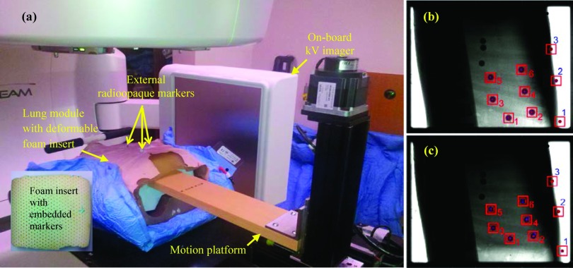
The phantom and the overall experimental setup are shown in Fig. 1(a). A commercially available dynamic breathing lung phantom (RS-1500, Radiology Support Devices, Inc., Long Beach, CA) was used as the outer shell. This shell is made from water-equivalent materials in the shape of a human torso, with an embedded ribcage and spinal column. The posterior half of this lung module is rigid, but the anterior half, which includes the chest surface and anterior rib cage, is composed of SuperFlab and is therefore flexible. The original insert for the inner cavity consists of a latex pouch filled with ∼3 mm diameter foam beads. This insert, while compressible, is not reproducibly deformable. (The study reported by Court et al.6 used the RS-1500 lung module with these manufacturer-supplied beads.) In order to enable programmable, reproducible deformation within the interior of the lung module, a custom-made insert was designed using an approximately 42 × 28 × 20 cm3 natural latex foam block [Fig. 1(a), inset]. Nine glass beads, each 9 mm in diameter, were embedded into the foam and four tungsten beads, each 2 mm in diameter, were placed on the surface of the torso. A piece of rigid foam was cut out in the shape of the opening of the cavity of the torso and served as the diaphragm. The lung module was immobilized using a Vacu-Lock bag placed inside a wingboard. The foam diaphragm was coupled to a high-precision programmable 3-axis motion platform developed at Washington University, St. Louis, MO.10 The coupled assembly was positioned on a Truebeam treatment couch, with the wingboard held in place by two-pin locating bars to aid reproducibility. For the remainder of our discussion, the entire assembly will be referred to as the phantom, while the individual components will be referred to as the lung module and the motion platform. In all experiments and illustrative examples described in this section, the motion platform was programmed with one-dimensional (1D) motion traces in the superior–inferior (SI) direction.
FIG. 1.
(a) Experimental setup for validation of the phantom, depicting the lung module, the 3-axis platform (used in 1D mode) used for motion actuation, and (inset) the latex foam insert. The locations of the external markers are indicated. Also shown are image frames in (b) inhale and (c) exhale phases, acquired using kV fluoroscopy. The three external and six internal markers segmented in the figure were used in the analysis.
2.B. Performance characterization
The performance of the phantom was characterized in terms of its ability to reproducibly simulate motion and the correlation between external and internal markers.
2.C. Validation of phantom
The motion platform was programmed, first with sinusoidal motion in the SI direction (±15 mm, 10 cycles per minute) and subsequently with ten patient traces (also in the SI direction) recorded in a previous study from lung cancer patients using the Synchrony system (Accuray, Sunnyvale, CA).11 The motion of internal and external markers was captured using the on-board kV imager on a Truebeam Linac. The kV imager was operated in fluoroscopic mode; 40 kVp, 70 mAs, 15 frames per second. Each acquisition lasted approximately 60 s. For each fluoroscopic sequence, image segmentation was performed frame-by-frame using a Hough transform in order to extract the centroid of each marker [Figs. 1(b) and 1(c)]. The motion trajectories of three external and six internal markers were constructed.
The reproducibility of motion trajectories for internal and external markers was determined by programming the aforementioned sinusoidal motion into the motion platform and acquiring five sets of fluoroscopic data and mapping the motion trajectories for the internal and external markers. For each marker, the trajectory corresponding to the first acquisition was treated as the reference with respect to which deviations of subsequent trajectories were calculated. These measurements were performed over several days of which one session is reported. Day-to-day systematic variations (<2 mm) were ascribed primarily to setup uncertainties (as seen from kV images).
Subsequently, the motion platform was programmed with ten tumor motion trajectories previously recorded from lung cancer patients using the Synchrony system.11 Correlation between the trajectories of the external and internal markers was calculated and linear regressions were performed for all external–internal combinations.
2.D. Geometric accuracy of the VisionRT surface photogrammetry system
As an example application, we used the phantom to validate the geometric accuracy of a clinically available surface photogrammetry system, Vision RT (Vision RT Ltd., London, United Kingdom). Briefly, this system projects a visible (red) optical pseudo-random speckle pattern on the thoraco-abdominal surface. A user-defined region-of-interest (ROI) is selected on the surface and imaged at a rate of 10 – 15 Hz. The system then computes a rigid-body transformation over the ROI in order to estimate the instantaneous motion-induced translational and rotational displacements. In our institution, we have a research version of this system which has high-speed-image-capture (HSIC) capability that enables the system to capture the entire surface pattern, represented by a point cloud ∼1.2 vertices/cm2, at a frequency of 8-10 Hz. This high capture rate is achieved by selecting a very small ROI (∼20 × 20 mm2 in this study) when the system monitors motion in real-time. While the small ROI enables a high frame capture rate, it does not provide adequate position information for the rigid-transformation-based calculation in the clinical software. Therefore, the time sequence of the surfaces captured by the HSIC was analyzed offline using in-house software developed in matlab (Mathworks, Inc.).
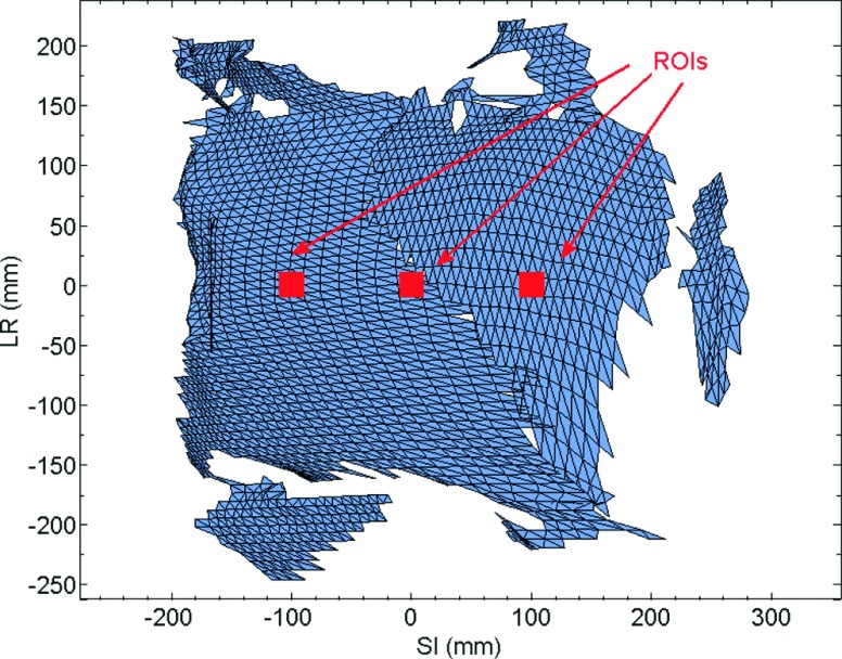
In this study, we quantified the accuracy of position information calculated from the VisionRT surface with respect to corresponding position information extracted from fluoroscopic image frames of externally placed radio-opaque markers. The motion platform was programmed with the aforementioned ten tumor motion trajectories. VisionRT surface data were recorded using the HSIC system at a rate of ∼10 Hz. Concurrently, sagittal kV fluoro images were acquired at ∼15 Hz. The surface data were postprocessed in the following manner. A 20 × 20 mm2 ROI was selected around each external marker [Fig. 2]. For each ROI, the average motion trajectory of the points within, along the SI direction, was computed. Each motion trajectory was compared with the kV fluoro-derived trajectory of the corresponding external marker.
FIG. 2.
Regions of interest (20 × 20 mm2) selected around each of the three external markers.
2.E. Validation of an image registration software tool
In this study, the phantom was used to validate an image registration tool, NiftyReg (University College London, UK).12 NiftyReg is an open-source software for medical image registration, which provides rigid as well as deformable image registration (DIR) algorithms. The motion platform was programmed with a sinusoidal motion trace and subsequently with a patient-derived lung tumor motion trace. Fluoroscopic scans were acquired for both traces to track motion trajectories of four internal markers and two external radio-opaque markers. Ground truth motion trajectories were obtained by segmenting the markers in each frame of the fluoro sequence using the techniques described in the phantom validation experiment.
For each fluoroscopic sequence acquired, frame-by-frame deformable image registrations were performed and a time series of deformation vector fields [DVF(t)] was obtained. The location of each marker was identified in the first frame of the fluoro sequence and the motion trajectories of the makers were calculated from the DVF(t). Each motion trajectory was compared with the corresponding ground truth.
2.F. Quantifying the geometric error due to irregular motion in 4DCT
4DCT has become the workhorse of modern motion-managed thoracic radiotherapy. In this technique, CT projections are acquired over several respiratory cycles and then sorted into 6-10 volumes to form a single average cycle.13–15 It is well-recognized that this technique does not account for cycle-to-cycle variations, which typical patients exhibit.11,16
In this example, we used the phantom to quantify the error in 4DCT-based position estimation in the presence of irregular respiratory motion. The phantom was placed inside the bore of a commercial 16-slice CT scanner (Brilliance CT Big Bore, Phillips, Amsterdam, Netherlands). An abdominal pressure belt was placed around the lung module (to mimic our clinical 4DCT acquisition technique) and the motion platform was programmed with a sinusoidal (±15 mm, 10 cycles per minute) motion trace and patient trace recorded by the Synchrony system.11 For each of the ten phase-specific volumes reconstructed, the positions of four internal markers were manually segmented. The same setup and motion trajectories were repeated in the Linac room and kV fluoroscopic images were acquired using the on-board imager. Internal marker positions from the 4DCT volumes were overlaid upon the motion trajectories derived from the fluoroscopic time series to calculate the difference between estimated (4DCT) and “actual” (kV fluoro) positions.
3. RESULTS
3.A. Reproducibility
Tables I and II list root mean square errors (RMSE) and ranges of motion for six internal and three external markers over five repeated measurements for the same sinusoidal motion trajectory. Overall, all of the marker trajectories exhibited high levels of reproducibility. The RMSE for internal markers ranged from 0.09 to 0.24 mm in the SI direction and from 0.06 to 0.25 mm in the AP direction. Corresponding values of RMSE for external markers were 0.05 to 0.14 mm (SI) and 0.02 to 0.13 mm (AP). As expected, higher RMSE values are observed for markers closer to the diaphragm which exhibit larger amplitude of motion.
TABLE I.
RMSE of internal marker trajectories over five consecutive measurements and corresponding range of motion.
| RMSE (mm) | Range of motion (mm) | |||
|---|---|---|---|---|
| Internal marker | SI | AP | SI | AP |
| 1 | 0.24 | 0.08 | 10.89 | 2.17 |
| 2 | 0.21 | 0.08 | 9.31 | 2.44 |
| 3 | 0.09 | 0.08 | 2.31 | 0.53 |
| 4 | 0.09 | 0.06 | 3.72 | 1.72 |
| 5 | 0.15 | 0.25 | 1.43 | 1.48 |
| 6 | 0.10 | 0.10 | 2.17 | 1.13 |
TABLE II.
RMSE of external marker trajectories over five consecutive measurements and corresponding range of motion.
| RMSE (mm) | Range of motion (mm) | |||
|---|---|---|---|---|
| External marker | SI | AP | SI | AP |
| 1 | 0.14 | 0.13 | 5.65 | 4.53 |
| 2 | 0.09 | 0.04 | 3.67 | 1.61 |
| 3 | 0.05 | 0.02 | 1.97 | 0.46 |
3.B. External and internal correlation
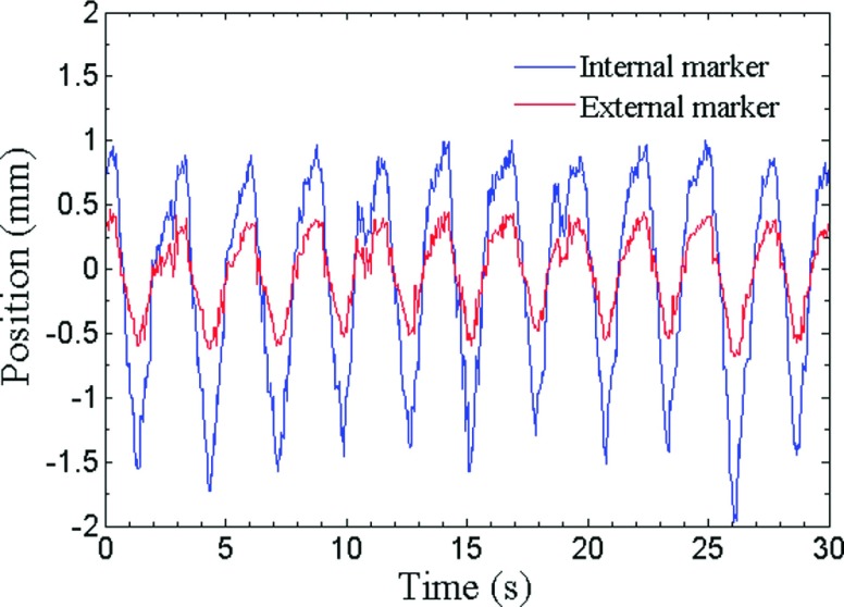
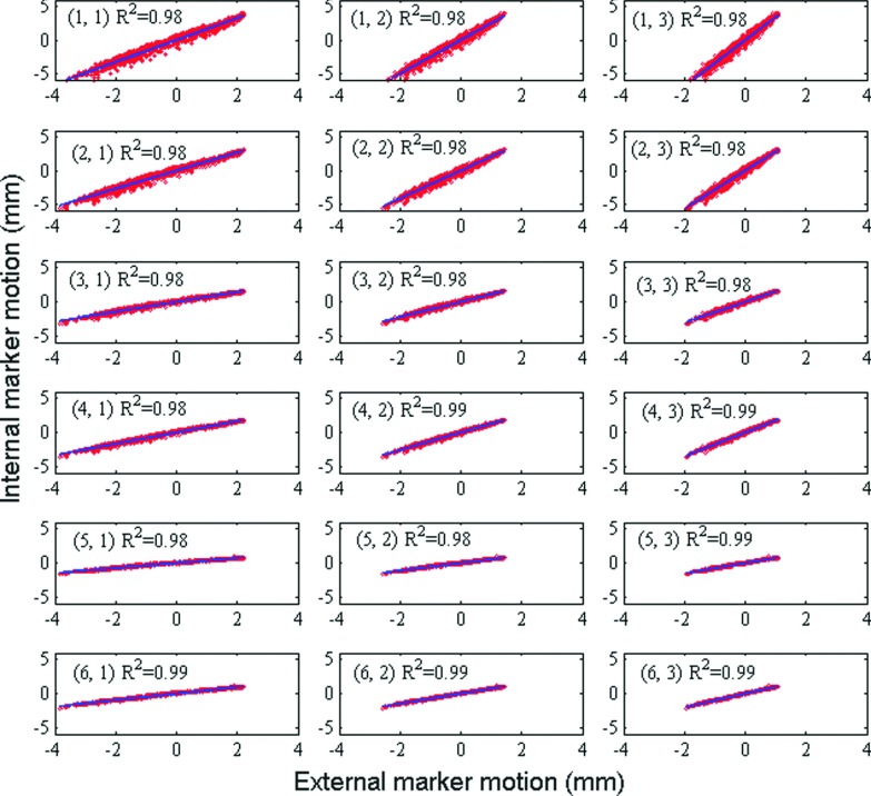
Figure 3 shows trajectories of one internal marker and one external marker for patient respiratory profile #1. Figure 4 shows linear regression between trajectories in SI direction of each external–internal marker pair in one measurement, along with the corresponding coefficients of determination of linear regression R2. There exists consistently high correlation between external and internal markers over all motion trajectories. Mean values of R2 between SI motion of internal and external markers over all ten patient-derived motion traces are listed in Table III. External markers #2 and #3 show slightly but consistently higher correlation with internal markers than external marker #1. We suspect that this effect may be due to overlying structures and consequent uncertainties in image segmentation for marker #1.
FIG. 3.
A plot of trajectories in AP direction of one internal marker and one external marker for patient respiratory profile #1.
FIG. 4.
Linear regression between trajectories in SI direction of marker pairs (internal marker #, external marker #) in one measurement.
TABLE III.
Average R2 between internal and external trajectories over ten patient motion traces.
| External marker | |||
|---|---|---|---|
| Internal marker | 1 | 2 | 3 |
| 1 | 0.89 | 0.94 | 0.95 |
| 2 | 0.90 | 0.95 | 0.96 |
| 3 | 0.91 | 0.96 | 0.96 |
| 4 | 0.95 | 0.99 | 0.99 |
| 5 | 0.87 | 0.91 | 0.91 |
| 6 | 0.96 | 0.99 | 0.99 |
3.C. Hysteresis
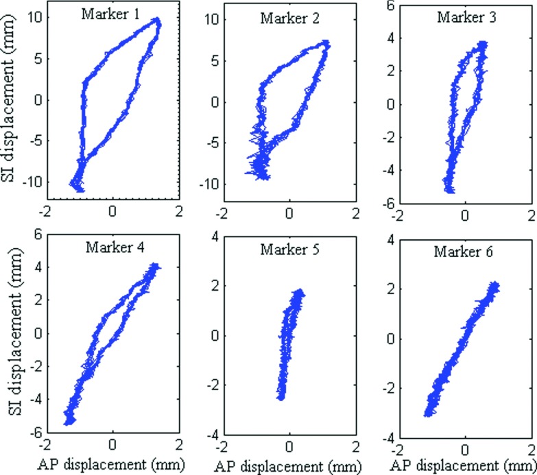
The design of the phantom allows the latex lung insert to deform differently from inhalation to exhalation and exhalation to inhalation. As a result, marker trajectories show various extents of hysteresis, analogous to that observed in actual respiratory motion. Figure 5 shows plots of SI motion vs AP motion for six internal markers. Markers closest to the diaphragm (#1 and #2) exhibit significantly larger amount of hysteresis while markers located further away show progressively reduced amounts of displacement as well as hysteresis. Finite but significantly less hysteresis was observed in the external markers (not shown for brevity).
FIG. 5.
SI vs AP motion of internal markers, showing various extents of hysteresis.
3.D. Geometric accuracy of VisionRT
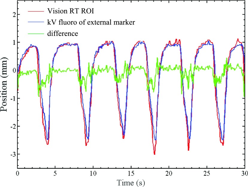
Figure 6 shows the AP trajectory of external marker #2 derived from kV fluoroscopic images (treated as the ground truth). Also superimposed is the AP trajectory of an ROI on the phantom surface encompassing the marker, as measured by VisionRT. The VisionRT trajectory follows the kV fluoro trajectory quite closely with sub 1-mm difference. Table IV lists RMSE between VisionRT ROI trajectories in AP direction and the corresponding external marker trajectories extracted from fluoroscopy. Also shown are the maximum differences and standard deviation (STD) between trajectory pairs. The RMSE between VisionRT measurements and synchronous fluoroscopically acquired external marker trajectories varies between 0.09 and 0.97 mm over ten patient-derived motion traces, indicating that the VisionRT system is capable of achieving sub 1-mm geometric accuracy of surface monitoring for realistic respiratory motion.
FIG. 6.
Motion trajectories of a VisionRT ROI and a synchronous fluoroscopically acquired trajectory of external marker #2.
TABLE IV.
RMSE, maximum difference, and standard deviation between motion trajectories obtained from fluoroscopy of external radio-opaque markers and from corresponding ROIs monitored by VisionRT.
| ROI #1 (around external marker #1) | ROI #2 (around external marker #2) | ROI #3 (around external marker #3) | |||||||
|---|---|---|---|---|---|---|---|---|---|
| Patient respiratory profile | RMSE (mm) | Maximum difference (mm) | STD (mm) | RMSE (mm) | Maximum difference (mm) | STD (mm) | RMSE (mm) | Maximum difference (mm) | STD (mm) |
| 1 | 0.16 | 0.80 | 0.76 | 0.23 | 0.83 | 0.70 | 0.20 | 0.67 | 0.44 |
| 2 | 0.17 | 0.62 | 0.62 | 0.21 | 0.56 | 0.56 | 0.20 | 0.66 | 0.39 |
| 3 | 0.16 | 0.97 | 0.57 | 0.23 | 0.89 | 0.53 | 0.16 | 0.55 | 0.34 |
| 4 | 0.20 | 0.83 | 0.70 | 0.22 | 0.84 | 0.63 | 0.19 | 0.64 | 0.39 |
| 5 | 0.15 | 0.72 | 0.38 | 0.16 | 0.87 | 0.32 | 0.18 | 0.55 | 0.28 |
| 6 | 0.13 | 0.47 | 0.45 | 0.16 | 0.53 | 0.30 | 0.17 | 0.51 | 0.31 |
| 7 | 0.09 | 0.45 | 0.32 | 0.14 | 0.38 | 0.24 | 0.18 | 0.47 | 0.25 |
| 8 | 0.20 | 1.27 | 0.61 | 0.23 | 0.78 | 0.55 | 0.19 | 0.73 | 0.36 |
| 9 | 0.26 | 1.48 | 1.30 | 0.24 | 0.97 | 1.22 | 0.21 | 0.68 | 0.66 |
| 10 | 0.30 | 1.33 | 1.01 | 0.26 | 0.90 | 0.94 | 0.23 | 0.69 | 0.57 |
3.E. Validation of NiftyReg image registration tool
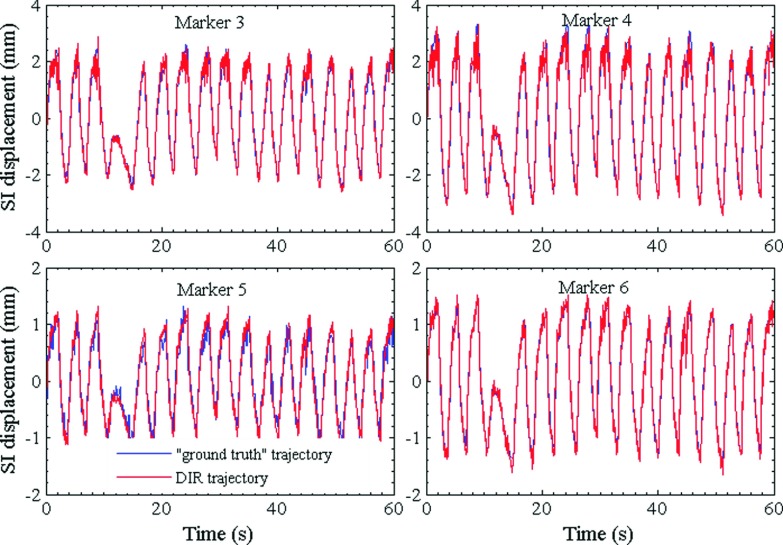
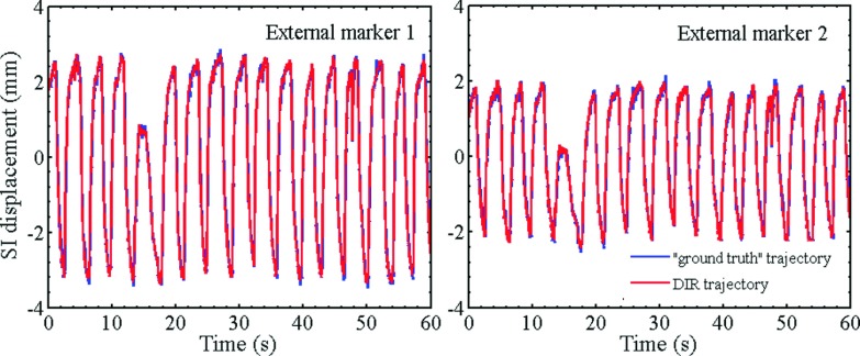
Figures 7 and 8 show the plots of trajectories of four internal markers and two internal markers, respectively, computed from DVF(t) which were obtained by registering the image from each fluoro sequence using NiftyReg. As a ground truth, corresponding trajectories obtained by segmenting the markers in each image frame are also shown. The RMS differences of all trajectories pairs computed by the two techniques are listed in Table V. In all cases, the marker trajectories extracted by NiftyReg closely resemble those computed by segmentation. The RMSE varies from 0.1 to 0.3 mm indicating high accuracy of the deformable registration algorithm.
FIG. 7.
Patient-derived SI trajectories of internal markers computed using DVFs. The DVFs were obtained by applying deformable image registration to a kV fluoroscopic time series. Also shown for comparison are “ground truth” trajectories obtained by segmenting the markers in individual frames of the fluoro sequence.
FIG. 8.
Patient-derived SI trajectories of external markers computed from NiftyReg DVFs and compared with ground truth trajectories obtained by segmentation of kV fluoro images.
TABLE V.
RMS differences between marker trajectories computed by deformable image registration and trajectories computed by image segmentation for a patient motion trace.
| Internal markers | External markers | |||||
|---|---|---|---|---|---|---|
| RMSE | 1 | 2 | 3 | 4 | 1 | 2 |
| SI (mm) | 0.23 | 0.30 | 0.16 | 0.10 | 0.28 | 0.20 |
| AP (mm) | 0.21 | 0.13 | 0.17 | 0.11 | 0.19 | 0.20 |
3.F. Validation of 4DCT
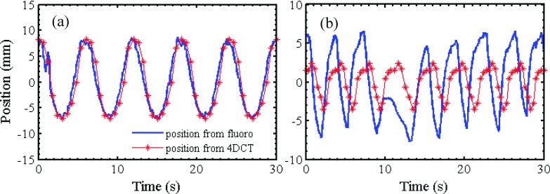
Figures 9(a) and 9(b) show sinusoidal and patient-derived SI motion trajectories respectively obtained via manually segmenting an internal marker from fluoroscopic images. For the same motion traces, marker positions segmented from breathing phases of a 4DCT scan are superimposed and the cycle is duplicated over the duration of motion (as assumed in clinical 4DCT). As expected, under conditions of well-behaved, periodic sinusoidal motion, the repeated 4DCT marker positions match closely to the corresponding fluoroscopic trajectories. However, when an actual patient trace is used, the 4DCT-derived positions show significant mismatch with the fluoroscopic trajectory. Table VI lists the RMS differences between 4DCT-derived and fluoroscopically derived positions for four internal markers. In each case, the RMSE for the patient-derived motion is approximately twice as high as that for sinusoidal motion, indicating the potential errors (e.g., geometric miss and/or overdose) that can arise if cycle-to-cycle variations in respiratory motion are not adequately accounted for in the treatment planning process.
FIG. 9.
SI positions of an internal marker computed from 4DCT and kV fluoroscopy for (a) a sinusoidal motion trace and (b) a patient motion trace.
TABLE VI.
RMS differences of marker trajectories obtained from 4DCT and trajectories extracted from fluoroscopic scans.
| Internal marker # | ||||
|---|---|---|---|---|
| RMSE (mm) | 1 | 2 | 3 | 4 |
| Sinusoidal trajectory | 1.71 | 2.88 | 0.38 | 0.69 |
| Patient trajectory | 4.24 | 5.32 | 1.05 | 1.43 |
4. DISCUSSION AND CONCLUSION
We have developed and validated an anthropomorphic, programmable, and externally and internally deformable lung phantom for thoracic radiotherapy applications. The phantom is designed to be modular and can be assembled from commercially available components. The only custom-made module in our case was the 3D motion platform from Washington University (already available to us), which can be easily replaced by a commercially available programmable 1D motion stage. The experiments in this study show that the phantom exhibits good fidelity, reproducibility, and realistic effects such as hysteresis for mathematically derived as well as patient-derived respiratory motion trajectories.
Human respiration uses relatively few motion actuators to produce complex motion. Respiratory motion is actuated by two muscle groups (scalene+intercostal for chest breathing and diaphragmatic+abdominal for abdominal breathing). It is characterized by variable amplitude, variable frequency, external and internal deformations, interplay between organs, and hysteresis.11 As observed from the trajectories of external and internal markers in Fig. 3, 4, 6-9, the prototype design uses a single motion actuator and produces these effects. Therefore, this prototype behaves closer to human respiration than other rigid+rigid or rigid+deformable designs, which produce some but not all of the above effects.
These capabilities of external and internal deformations open up the possibility of clinical testing applications that may not be possible using other phantom designs. One example is assessing the impact of variation in external surrogate placement or ROI selection on 4DCT images. Clinically, 4DCT slices are sorted using a respiratory motion trace from an external surrogate, e.g., optical marker(s), abdominal belt, ROI from surface photogrammetry. Marker placement variations can cause variations in amplitude of the motion trace as well as phase offsets between external points and internal structures, leading to significant differences in 4DCT phase estimation and errors in target localization.17,18 The prototype phantom can be easily employed to characterize such errors for arbitrarily many external markers and marker placements. A phantom design based on a rigid-exterior+rigid or deformable interior will not be appropriate for such characterization.
The three used cases described in this work are illustrative of other applications that the prototype phantom can be used for. Prominent among these applications is the use of this phantom to validate the geometric accuracy of clinically used surrogate-based patient monitoring systems. These include systems based on purely external surrogates such as external markers (e.g., RPM) and surface photogrammetry (e.g., VisionRT Ltd., C-RAD); systems based on internal surrogates such as implanted gold fiducials or electromagnetic beacons (e.g., Calypso) and; systems that use a combination of external and internal surrogates (Synchrony, Accuray).
It is important, nevertheless, to understand the design limitations of the phantom and therefore its indications and contraindications for clinical quality assurance (QA). The users of all surrogate-based monitoring systems make the implicit assumption that there is one-to-one correspondence between the position information given by the monitoring system and the position of the tumor. In an actual patient, this correlation may change or may not be sufficiently strong (which is why most users update the surrogate information with daily/weekly imaging). The biomechanics of human respiration are quite complex. In addition to 3D translation, rotation, and deformation, there is sliding motion between the lobes of the lung and the inner chest wall surface as well as sliding between adjacent lobes. On a patient-specific level, especially for lung cancer patients, there may be comorbidities such as partial or complete emphysema, pneumonitis, atelectasis, fibrosis, paralysis of diaphragm, etc., which can further alter the nature and strength of correlation of the tumor position with that of external and even internal surrogates. In contrast, the phantom will always exhibit high external-to-internal correlation due to the fact that there is a single mechanical actuator that generates the motion. Thus, when this phantom is used in the validation of a patient monitoring system, all it can test is how accurate and reproducible is the system in calculating the position of external and/or internal surrogates in a deforming anatomy. The phantom cannot be used to test the ability of a system to predict tumor position in an actual patient nor, by extension, as a patient-specific QA tool. In this context, several researchers have discussed the use of patient-specific virtual phantoms derived from digital 3D and 4D image data to use in patient-specific QA for thoracic and abdominal radiotherapy applications.19–21
There are several enhancements and modifications that are being considered for future prototypes. First, in order to make the phantom more useful in clinical applications, it would be desirable to modify the design so as to enable the user to change the external–internal correlation. This feature can be used to test the ability of model-based monitoring systems such as Synchrony to correctly determine tumor position based on external and internal surrogates. Second, the phantom inserts could be modified so as to be dosimetrically similar to lung tissue and internal organs. Efforts on creating lung-equivalent material have been described by Kashani et al., who soaked the foam insert of their phantom in iodine solution of appropriate concentration to match CT values of human lungs.5 Court et al. created a replica of a lung tumor from a gel using 3D printing and attached dosimeters around the tumor.6 Finally, efforts are ongoing in our group to interface the phantom with an MRI-compatible motion platform in order to create a multimodality test tool for integrated MRI+radiotherapy systems that are being investigated and clinically deployed within the community.
ACKNOWLEDGMENTS
This work was partially supported through research funding from the National Institutes of Health (R01CA169102), Varian Medical Systems, Palo Alto, CA, and Vision RT Ltd., London, UK.
REFERENCES
- 1.Yan H., Zhu G., Yang J., Lu M., Ajlouni M., Kim J. H., and Yin F. F., “The investigation on the location effect of external markers in respiratory-gated radiotherapy,” J. Appl. Clin. Med. Phys. 9, 57–68 (2008). [DOI] [PMC free article] [PubMed] [Google Scholar]
- 2.Serban M., Heath E., Stroian G., Collins D. L., and Seuntjens J., “A deformable phantom for 4D radiotherapy verification: Design and image registration evaluation,” Med. Phys. 35, 1094–1102 (2008). 10.1118/1.2836417 [DOI] [PubMed] [Google Scholar]
- 3.Chang J., Suh T. S., and Lee D. S., “Development of a deformable lung phantom for the evaluation of deformable registration,” J. Appl. Clin. Med. Phys. 11, 281–286 (2010). [DOI] [PMC free article] [PubMed] [Google Scholar]
- 4.Nioutsikou E., Richard N. S.-T. J., Bedford J. L., and Webb S., “Quantifying the effect of respiratory motion on lung tumour dosimetry with the aid of a breathing phantom with deforming lungs,” Phys. Med. Biol. 51, 3359–3374 (2006). 10.1088/0031-9155/51/14/005 [DOI] [PubMed] [Google Scholar]
- 5.Kashani R., Lam K., Litzenberg D., and Balter J., “Technical note: A deformable phantom for dynamic modeling in radiation therapy,” Med. Phys. 34, 199–201 (2007). 10.1118/1.2400612 [DOI] [PubMed] [Google Scholar]
- 6.Court L. E., Seco J., Lu X. Q., Ebe K., Mayo C., Ionascu D., Winey B., Giakoumakis N., Aristophanous M., Berbeco R., Rottman J., Bogdanov M., Schofield D., and Lingos T., “Use of a realistic breathing lung phantom to evaluate dose delivery errors,” Med. Phys. 37, 5850–5857 (2010). 10.1118/1.3496356 [DOI] [PubMed] [Google Scholar]
- 7.Niu C. J., Foltz W. D., Velec M., Moseley J. L., Al-Mayah A., and Brock K. K., “A novel technique to enable experimental validation of deformable dose accumulation,” Med. Phys. 39, 765–776 (2012). 10.1118/1.3676185 [DOI] [PMC free article] [PubMed] [Google Scholar]
- 8.Remmert G., Biederer J., Lohberger F., Fabel M., and Hartmann G. H., “Four-dimensional magnetic resonance imaging for the determination of tumour movement and its evaluation using a dynamic porcine lung phantom,” Phys. Med. Biol. 52, N401–N415 (2007). 10.1088/0031-9155/52/18/n02 [DOI] [PubMed] [Google Scholar]
- 9.Steidl P., Richter D., Schuy C., Schubert E., Haberer T., Durante M., and Bert C., “A breathing thorax phantom with independently programmable 6D tumour motion for dosimetric measurements in radiation therapy,” Phys. Med. Biol. 57, 2235–2250 (2012). 10.1088/0031-9155/57/8/2235 [DOI] [PubMed] [Google Scholar]
- 10.Malinowski K., Lechleiter K., Hubenschmidt J., Low D., and Parikh P., “Use of the 4D phantom to test real-time targeted radiation therapy device accuracy,” Med. Phys. 34, 2611 (2007). 10.1118/1.2761600 [DOI] [Google Scholar]
- 11.Suh Y., Dieterich S., Cho B., and Keall P. J., “An analysis of thoracic and abdominal tumour motion for stereotactic body radiotherapy patients,” Phys. Med. Biol. 53, 3623–3640 (2008). 10.1088/0031-9155/53/13/016 [DOI] [PubMed] [Google Scholar]
- 12.Modat M., McClelland J., and Ourselin S., “Lung registration using the NiftyReg package,” Med. Image Anal. Clin.-A Grand Challenge 33–42 (2010). [Google Scholar]
- 13.Mageras G. S., Pevsner A., Yorke E. D., Rosenzweig K. E., Ford E. C., Hertanto A., Larson S. M., Lovelock D. M., Erdi Y. E., Nehmeh S. A., Humm J. L., and Ling C. C., “Measurement of lung tumor motion using respiration-correlated CT,” Int. J. Radiat. Oncol., Biol., Phys. 60, 933–941 (2004). 10.1016/j.ijrobp.2004.06.021 [DOI] [PubMed] [Google Scholar]
- 14.Keall P., “4-dimensional computed tomography imaging and treatment planning,” Semin. Radiat. Oncol. 14, 81–90 (2004). 10.1053/j.semradonc.2003.10.006 [DOI] [PubMed] [Google Scholar]
- 15.Wink N., Panknin C., and Solberg T. D., “Phase versus amplitude sorting of 4D-CT data,” J. Appl. Clin. Med. Phys. 7, 77–85 (2006). 10.1120/jacmp.2027.25373 [DOI] [PMC free article] [PubMed] [Google Scholar]
- 16.Seppenwoolde Y., Shirato H., Kitamura K., Shimizu S., van Herk M., Lebesque J. V., and Miyasaka K., “Precise and real-time measurement of 3D tumor motion in lung due to breathing and heartbeat, measured during radiotherapy,” Int. J. Radiat. Oncol., Biol., Phys. 53, 822–834 (2002). 10.1016/s0360-3016(02)02803-1 [DOI] [PubMed] [Google Scholar]
- 17.Chi P. C., Balter P., Luo D., Mohan R., and Pan T., “Relation of external surface to internal tumor motion studied with cine CT,” Med. Phys. 33, 3116–3123 (2006). 10.1118/1.2241993 [DOI] [PubMed] [Google Scholar]
- 18.Killoran J. H., Allen A. M., Kann B. H., and Lyatskaya Y., “Inter fractional variability of breathing phase definition as determined by fiducial location,” Med. Phys. 35, 753–763 (2008). 10.1118/1.2828197 [DOI] [PubMed] [Google Scholar]
- 19.Stanley N., Glide-Hurst C., Kim J., Adams J., Li S., Wen N., Chetty I. J., and Zhong H., “Using patient-specific phantoms to evaluate deformable image registration algorithms for adaptive radiation therapy,” J. Appl. Clin. Med. Phys. 14, 177–194 (2013). 10.1120/jacmp.v14i6.4363 [DOI] [PMC free article] [PubMed] [Google Scholar]
- 20.Williams C. L., Mishra P., Seco J., James S. S., Mak R. H., Berbeco R. I., and Lewis J. H., “A mass-conserving 4D XCAT phantom for dose calculation and accumulation,” Med. Phys. 40, 071728 (10pp.) (2013). 10.1118/1.4811102 [DOI] [PMC free article] [PubMed] [Google Scholar]
- 21.Segars W. P., Bond J., Frush J., Hon S., Eckersley C., Williams C. H., Feng J., Tward D. J., Ratnanather J. T., Miller M. I., Frush D., and Samei E., “Population of anatomically variable 4D XCAT adult phantoms for imaging research and optimization,” Med. Phys. 40, 043701 (11pp.) (2013). 10.1118/1.4794178 [DOI] [PMC free article] [PubMed] [Google Scholar]


