



Abstract
In this paper, we present a system capable of automatically steering a bevel-tipped flexible needle under ultrasound guidance toward a physical target while avoiding a physical obstacle embedded in gelatin phantoms and biological tissue with curved surfaces. An ultrasound pre-operative scan is performed for three-dimensional (3D) target localization and shape reconstruction. A controller based on implicit force control is developed to align the transducer with curved surfaces to assure the maximum contact area, and thus obtain an image of sufficient quality. We experimentally investigate the effect of needle insertion system parameters such as insertion speed, needle diameter and bevel angle on target motion to adjust the parameters that minimize the target motion during insertion. A fast sampling-based path planner is used to compute and periodically update a feasible path to the target that avoids obstacles. We present experimental results for target reconstruction and needle insertion procedures in gelatin-based phantoms and biological tissue. Mean targeting errors of 1.46 ± 0.37 mm, 1.29 ± 0.29 mm and 1.82 ± 0.58 mm are obtained for phantoms with inclined, curved and combined (inclined and curved) surfaces, respectively, for insertion distance of 86–103 mm. The achieved targeting errors suggest that our approach is sufficient for targeting lesions of 3 mm radius that can be detected using clinical ultrasound imaging systems.
Keywords: Computer-assisted surgery, Minimally invasive procedures, Ultrasound, Needle steering
1. Introduction
Needle insertion into soft-tissue is a minimally invasive procedure used for diagnostic and therapeutic purposes such as biopsy and brachytherapy, respectively. In the current study, we present an image-guided robotic system that scans the soft-tissue phantom with a curved surface to localize the target and reconstruct its shape, pre-operatively. The image-guided robotic system then steers the needle to reach the localized target position while avoiding obstacles (Fig. 1). Two-dimensional (2D) and three-dimensional (3D) ultrasound imaging were used to localize the target and the needle during needle insertion [1]. The ultrasound transducer used for visualization of the needle and target needs to be controlled in order to scan the curved surface of the soft-tissue phantom. An algorithm based on implicit force control is proposed to move a transducer over a curved surface to maximize contact surface area for improved needle and target visualization.
Fig. 1.

The experimental setup used for needle insertion into a soft-tissue phantom that includes biological tissue (chicken breast tissue) with a curved surface. The inset shows an ultrasound transducer moving over a curved surface.
The effect of system parameters on needle deflect and target movement during biopsy were investigated in several studies [2–5]. These parameters include needle diameter, insertion speed and bevel angle. Prior to needle insertion, these parameters can be set to minimize the target movement during insertion and consequently, improve the targeting accuracy.
1.1. Related work
In previous studies, robotic systems have been used to control the ultrasound transducer for scanning [6–9]. An example of an early study that explores the advantage of robotic ultrasound systems for scanning curved surfaces is the development of Hippocrate, a robot arm for medical applications with force feedback [10]. One of the applications of Hippocrate is the manipulation of an ultrasound transducer on a patient’s skin in an automatic manner while maintaining a constant exerted force. The ultrasound images are used to reconstruct the 3D profile of arteries. The same robot has been used in studies of Krupa et al. that investigated an ultrasound-based visual servoing system [11,12]. Abolmaesumi et al. developed a tele-operated ultrasound system that allows the radiologist to view and manipulate the ultrasound transducer at remote site, while being assisted by force and image servo controllers [13]. Javier et al. developed an ultrasound system to 3D reconstruct the shape of in-vitro stenoses using an industrial robotic arm with force feedback [14]. Nadeau et al. presented a hybrid visual/force control to automatically align the transducer and keep the ultrasound image static even in the presence of physiological motion disturbances [15]. Besides proper contact force, the alignment/orientation of the ultrasound transducer is important to maintain the image quality. This alignment can be achieved by visual servoing [11] and also by force/torque control. However, the presented scanning systems require a pre-determined transducer path. This means that any deformation or change in the path causes scanning inaccuracies and consequently, errors in needle steering.
Flexible needles are used to steer around sensitive and hard tissue such as blood vessels and bones, respectively [16–18]. Such needles are fabricated with an asymmetric tip (bevel tip) that naturally deflect during insertion into soft-tissue [19]. The needle deflection due to its tip-asymmetry is used to steer the needle toward a certain target position [20,17]. In previous studies, control algorithms were developed for needle steering in 2D space. DiMaio and Salcudean presented a path planning and control algorithm that related the needle motion at the base (outside the soft-tissue phantom) to the tip motion inside the tissue [21]. Abayazid et al. presented a 2D ultrasound image-guided steering algorithm, and a 3D steering algorithm where they used Fiber Bragg Grating sensors for feedback [22,23]. Several 3D path planning algorithms have been introduced that are based on rapidly exploring random trees (RRTs) [24,25]. Our approach integrates the algorithm presented by Patil et al. to quickly compute feasible, collision-free paths in 3D-space [25].
1.2. Contributions
In the current study, we introduce a complete system where we scan a curved (breast-like) soft-tissue phantom to localize the target and obstacle positions, and also reconstruct the target shape. In previous studies, the ultrasound-guided steering experiments were performed on soft-tissue phantoms with flat surfaces but this is not the case in many needle insertion procedures such as breast biopsy [26,27]. In the current study, a robot is used to control the ultrasound transducer to keep contact between the transducer and the curved surface of the soft-tissue phantom using force feedback. We then integrate 3D tracking, path planning and control algorithms to steer a bevel-tipped flexible needle in a curved phantom to reach the localized target in 3D-space while avoiding a physical obstacle. Before conducting the insertion experiments, we investigate experimentally the effect of system parameters on target movement in biological tissue. The parameters include the needle insertion speed, bevel angle, needle diameter, skin thickness, target distance and target size. The results of this study is used to select the system parameters that reduce the target motion to minimize the targeting error while steering the needle. The algorithms are validated by conducting insertion experiments into a soft-tissue phantom and biological tissue (ex vivo chicken breast tissue) while avoiding a physical obstacle. To the best of our knowledge, the use of 3D ultrasound tracking combined with 3D path planning for needle steering toward a target and avoiding physical obstacles in a curved phantom has not been demonstrated.
2. Ultrasound scanning over curved surfaces
In this section, we present a method for ultrasound scanning of phantoms with curved surfaces. The scan is performed in steps using an ultrasound transducer. The target location is estimated using the ultrasound images that are captured at the end of each scanning step. Proper contact between the ultrasound transducer and the phantom surface is crucial for generating ultrasound images. A five degrees-of-freedom (DOF) device is designed in order to properly scan curved surfaces using a 2D ultrasound transducer. The system is an extension of the 3DOF Cartesian transducer positioning device presented by Vrooijink et al. [28]. In this study, a rotational mechanism is attached to the previous device in order to include two more DOF (Fig. 2).
Fig. 2.

Ultrasound transducer positioning device with a 2 degrees-of-freedom rotational mechanism. The positioning device provides movements in x-, y- and z-axis and the rotation mechanism allows for pitch (θ) and roll (ϕ) movements. The force/torque sensor is attached to the rotational mechanism to measure the contact force (fc) and the torque (tx) round the x-axis. The geometry of the curved phantom consists of different inclination angles. The dimensions of the cuboidal flat phantom are 230 mm × 148 mm × 48 mm.
2.1. Mechanical design
The ultrasound positioning device is augmented with a 2-DOF rotational mechanism. The mechanism design allows the transducer to roll and pitch using differential gears (Fig. 2). The midpoint of the transducer contact surface is assumed to be the end-effector of the system. The rotational mechanism is actuated by two ECMax22 motors with GP22 gear head (Maxon Motor, Sachseln, Switzerland), which are controlled by Elmo Whistle 2.5/60 motor controller (Elmo Motion Control Ltd, Petach-Tikva, Israel). The system has a force/torque sensor (ATI Nano-17, Industrial Automation, USA) to measure the contact forces applied to the transducer. The force measurements are used to align the transducer contact surface with the curved phantom surface.
2.2. Alignment control algorithm
A controller based on implicit force control [29], is developed to align the transducer with the phantom surface. The alignment control is important to assure the maximum contact area between the transducer and the phantom. The alignment control is done in three steps as described in Algorithm 1, where fref–c is the reference contact force, fc is the exerted contact force, fref is the vector with reference forces (which is non-zero only in the contact normal direction), fs is the vector force measured by the force/torque sensor, a is a constant, Kf is the controller gain, ve is the end-effector velocity, J† is the pseudo-inverse of the Jacobian of the robot and is the joint velocities. First, the transducer moves vertically downward until it gets in contact with the phantom with a reference contact force of 3 N. This reference force guarantees proper ultrasound images [30]. The alignment control loop keeps the exerted force constant using the implicit force control algorithm described in Algorithm 1. The Cartesian transducer velocities (ve) are defined by the force error (fs – fref) multiplied by the controller gain (Kf). The joint velocities of the rotational mechanism are then calculated using the pseudo-inverse of the Jacobian (J†). After aligning the transducer, the ultrasound image and the transducer pose are saved in order to be used as an input to the target localization algorithm. Finally, the transducer is moved forward a step of 0.4 mm in the scan direction, and again the control loop is executed. This step length is set to be equal to the thickness of the ultrasound image plane in order to prevent overlap or loss of ultrasound image data. The outputs of the alignment control algorithm are sequence of ultrasound image frames and the corresponding transducer pose at each step. The mean error of the alignment angle of the ultrasound transducer is 0.67 ± 0.33°. The detailed experimental evaluation and validation of the alignment control algorithm using force feedback are presented in [30].
| Algorithm 1 (Transducer alignment control during the scan). |
|
|
| while fc ≠ fref-c do |
| if fs > fref then |
| moveup() |
| else |
| movedown() |
| end if |
| end while |
| {Starting the scan with N steps} |
| for i = 0 : N do |
| while fc < fref-c – a or fref-c + a < fc do |
| ve = Kf (fs – fref) {End-effector velocity is defined by the force error} |
| = J†ve {Transform end-effector velocities to joint velocities} |
| SendVelocityCommand( ) {send the velocity commands to the robot} |
| end while |
| GetUltrasoundImage() {Save the ultrasound image} |
| GetTransducerPose() {Save the transducer pose} |
| MoveTransducer(StepSize) {move the transducer in the scan direction} |
| end for |
|
|
2.3. Target localization and shape reconstruction
The set of ultrasound images and the corresponding transducer poses while capturing the images are processed offline to determine the target location and reconstruct its 3D shape (Fig. 3). First, each image is inverted and has its contrast enhanced by a contrast-limited adaptive histogram equalization. The images are then converted to a binary image based on a threshold value. The image is morphologically closed resulting in the segmented cross-sectional view of the target. The center of mass of this segmented target area is computed for each image and the average of all centers of mass is defined as the target center of mass. The target surface is reconstructed using the contour points of the segmented images. The volume that this surface comprises is used to calculate the corresponding diameter. The target reconstruction is evaluated using the mean absolute distance (MAD) [31] and target shape is assumed to be an ideal sphere. The location of the reconstructed target is used as an input to the control algorithm to steer the needle toward the target.
Fig. 3.
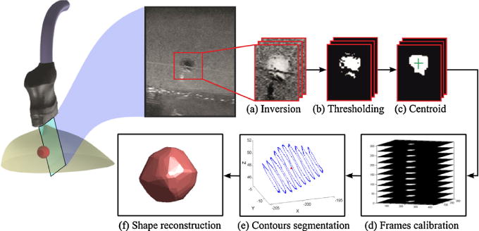
Target localization and reconstruction. (a) The image is inverted and the contrast is enhanced by transforming the values using contrast-limited adaptive histogram equalization. (b) The image is converted to a binary image based on threshold. (c) Small pixel groups are removed and the image is morphologically closed resulting in the final segmented image. (d) The binary images are staked together based on the position and orientation of the probe while acquiring each image frame. (e) The centroid of the target volume is calculated using all image frames that include the target. (f) The target surface is reconstructed using the contour points of the segmented images.
3. Ultrasound-guided needle steering
The ultrasound-based needle tracking algorithm provides the needle control algorithm with the tip position during insertion. The needle tracker used for feedback is based on the method presented by Vrooijink et al. [28]. The tracker is modified to allow the ultrasound probe to scan curved surfaces. The ultrasound image should visualize the needle tip, and the image plane should be always perpendicular to the needle insertion axis. This is achieved by moving the transducer with variable velocities to keep the needle tip in the image. The transducer orientation is kept constant by controlling the position of pitch and roll angles (Fig. 2). An implicit force control is implemented to keep the transducer orthogonal to the needle insertion axis and to properly adjust the probe position over the curved surface during the insertion. The desired probe velocity in z-axis (vz) is defined as
| (1) |
where k is the feedback gain, fd is the desired contact force and fc is the exerted contact force. Constant contact force is essential to keep the needle tip visible in the ultrasound images while steering.
The bevel-tipped needle is assumed to move along a path composed of circular arcs during insertion [19,32]. The needle path is computed by a path planner [25]. The planner is re-executed in a closed-loop manner using the tip pose estimated from the ultrasound imaging. The direction of the circular path depends on the orientation of the bevel tip. The bevel tip orientation is controlled by needle rotation about its insertion axis at the base. This rotation enables the needle to move along the planned path and reach the target position. Further details regarding the steering algorithm is presented in the work by Abayazid et al. [23].
4. Experimental results
This section presents the experimental setup used for target motion study, target reconstruction and needle steering. The aim of performing the target motion experiments is to determine the effect of needle parameters on target motion. The results are used to adjust the parameters to minimize the target motion during steering experiments. The results of the target reconstruction and steering experiments are also described in the current section.
4.1. Experimental setup
The experimental setup consists of a needle insertion device and an ultrasound transducer positioning device (Fig. 1). The insertion device has two DOFs: translation along and rotation about the needle insertion axis [22]. On the other hand, the positioning device has five DOFs and is designed to position an ultrasound transducer in 3D space [28]. The rotational mechanism with the force/torque sensor described in Section 2.1 to ensure having a sufficient ultrasound image quality.
4.2. Effect of needle parameters on target motion
The experiments are performed in a biological tissue (ex vivo chicken breast tissue). The default parameters include a 1 mm diameter nitinol needle with a 30° bevel angle which is inserted 40 mm into the biological tissue with a velocity of 4 mm/s. A 4 mm diameter silicone target is embedded into the biological tissue phantom, which is the size of a clinically significant tumor [33]. The silicon target is made using two different gel components, Wacker SilGel 612A (Wacker Chemie AG, Germany) and Wacker SilGel 612B. The components are mixed in a 1.5:1 ratio and then cast into a mold. The needle is inserted until it hits the target but does not penetrate it. Every experiment is performed five times.
The experimental plan is presented in Table 1 and results are presented in Fig. 4. The results show that increasing the insertion speed (between 1 mm/s and 30 mm/s) and target distance (between 10 mm and 50 mm) cause decrease in the target motion by 0.73 mm and 0.51 mm, respectively, while increasing the needle diameter (between 0.5 mm and 1.5 mm) and the skin thickness (between 0 mm and 1.6 mm) lead to increased target motion by 3.47 mm and 2.63 mm, respectively. Varying the target size or bevel angle does not influence the target motion.
Table 1.
Experimental plan for ultrasound measurements to investigate the effect of system parameters on target motion. Each experiment is repeated five times.
| System parameters | |||||||||||||||||||||||||
|---|---|---|---|---|---|---|---|---|---|---|---|---|---|---|---|---|---|---|---|---|---|---|---|---|---|
|
| |||||||||||||||||||||||||
| Experiment | Insertion speed (mm/s)
|
Bevel angle (°)
|
Needle diameter (mm)
|
Skin thickness (mm)
|
Target distance (mm)
|
Target diameter (mm)
|
|||||||||||||||||||
| 1 | 4 | 10 | 20 | 30 | 30 | 45 | 60 | 0.5 | 0.75 | 1 | 1.25 | 1.5 | 0 | 0.8 | 1.6 | 10 | 20 | 30 | 40 | 50 | 3 | 4 | 6 | 8 | |
| #1 | ✓ | ✓ | ✓ | ✓ | ✓ | ✓ | ✓ | ✓ | ✓ | ✓ | |||||||||||||||
| #2 | ✓ | ✓ | ✓ | ✓ | ✓ | ✓ | ✓ | ✓ | |||||||||||||||||
| #3 | ✓ | ✓ | ✓ | ✓ | ✓ | ✓ | ✓ | ✓ | ✓ | ✓ | |||||||||||||||
| #4 | ✓ | ✓ | ✓ | ✓ | ✓ | ✓ | ✓ | ✓ | |||||||||||||||||
| #5 | ✓ | ✓ | ✓ | ✓ | ✓ | ✓ | ✓ | ✓ | ✓ | ✓ | |||||||||||||||
| #6 | ✓ | ✓ | ✓ | ✓ | ✓ | ✓ | ✓ | ✓ | ✓ | ||||||||||||||||
Fig. 4.

Effect of system parameters (Table 1) on the absolute displacement of the target during needle insertion. (a) Needle insertion speed and bevel angle. (b) Skin thickness and needle diameter. (c) Target size and target distance.
4.3. Needle steering results
The needle parameters are selected based on the results presented in Section 4.2. A 0.5 mm diameter nitinol needle is used during the experiments as it minimizes the target motion. The bevel angle does not affect the target motion. A 30° bevel angle is used to increase the needle curvature and the steering capabilities of the needle [34]. The effect of needle insertion velocity on target motion is not significant as varying the insertion speed from 1 mm/s to 30 mm/s increases the target motion by less than 0.70 mm. In order to reduce the effect of delay of the steering system, we use 1 mm/s insertion velocity during the steering experiments. The target localization and shape reconstruction are determined by ultrasound scanning of the soft-tissue phantom surface before steering the needle (as described in Section2.3).
4.3.1. Experimental plan
Different experimental scenarios are conducted to evaluate the performance of the proposed target reconstruction, needle tracking, path planning and control algorithms. The needle radius of curvature (270 mm in the gelatin phantom), used as an input to the control algorithm, is determined empirically [23]. Closed-loop control corrects possible curvature deviations. The insertion distance ranges between 86 mm and 103 mm. Each experimental case is performed five times. Before every experiment the phantom is scanned to localize the 3 mm radius target and reconstruct its shape.
In Case 1, the steering algorithm controls the needle to avoid a cylindrical obstacle of 7.5 mm radius and reach the target in a soft tissue phantom with a flat surface. The phantom is placed on an inclined surface (Fig. 5(a)). In Case 2, the needle is steered to avoid the obstacle and reach the target embedded in a phantom with a curved surface (Fig. 5(b)). In Case 3, the needle is steered to avoid the obstacle and reach the target in biological tissue. The biological tissue is embedded into a curved gelatin phantom placed on an inclined surface (Fig. 5(c)).
Fig. 5.

Experimental cases. The steering algorithm controls the needle to avoid an obstacle reach a 3 mm radius target in a soft tissue phantom. (a) Case 1: the phantom is placed on an inclined surface. (b) Case 2: the phantom has an curved surface. (c) Case 3: the target is embedded in biological tissue. The biological tissue is embedded into a curved gelatin phantom placed on an inclined surface.
4.3.2. Results
The target reconstruction is evaluated using the MAD method and target shape is assumed to be an ideal sphere of 3 mm radius. The results of the MAD evaluation method and target radius obtained using the reconstruction algorithm are presented in Table 2.
Table 2.
The results of target reconstruction and steering experiments. The target reconstruction is evaluated using the mean absolute distance (MAD) geometric comparison method [31] assuming that the actual target shape is spherical (3 mm radius). The targeting error is the absolute distance between the target and needle tip at the end of insertion. Each experiment is performed five times.
| Cases | Target reconstruction
|
Needle steering Targeting error (mm) | |
|---|---|---|---|
| Radius | MAD (mm) | ||
| Case 1 | 2.88 ± 0.07 | 0.36 ± 0.05 | 1.46 ± 0.37 |
| Case 2 | 2.90 ± 0.18 | 0.38 ± 0.03 | 1.29 ± 0.29 |
| Case 3 | 2.95 ± 0.06 | 0.47 ± 0.06 | 1.82 ± 0.58 |
In the steering experimental cases presented in Fig. 5, the error is defined as the absolute distance between the tip and the center of the target that is localized pre-operatively. The experimental results for the experimental cases are also presented in Table 2. The needle tip reaches the target in each experimental trial. The maximum targeting error is 1.82 mm, and it is noted in Case 3. On the other hand, the minimum targeting error is 1.29 mm, and it is observed in Case 2. The results show that the targeting error increases while steering in biological tissue due to its inhomogeneity. The inhomogeneity of the biological tissue causes deviation of the needle from its circular path. Please refer to the accompanying video as supplementary material that demonstrates the experimental procedure and results.1
5. Conclusions and recommendations
This study introduces a complete steering system that combines pre-operative 3D target localization and shape reconstruction algorithms with intra-operative path planning and ultrasound-guided control algorithms to steer a bevel tip needle toward a physical target while avoiding a physical obstacle in soft-tissue phantoms. The effect of system parameters such as insertion speed, needle diameter and bevel angle on target motion during needle insertion are investigated experimentally. The results of this study can be used to improve target motion models and hence improve steering and path planning. An algorithm is developed using feedback from a force/torque sensor to keep the ultrasound transducer in contact with phantom surface to ensure sufficient images during the insertion procedure. Three experimental cases are performed to validate the steering system in soft-tissue phantoms and biological tissue (chicken breast) with inclined and curved surfaces. The phantom is scanned before every experimental trial to localize the target and reconstruct its shape. The reconstruction evaluation method (MAD) results for the three experimental cases are 0.36 ± 0.05 mm, 0.38 ± 0.03 mm and 0.47 ± 0.06 mm, respectively. The steering experimental results show that needle reaches the target in each experimental trial and the mean targeting errors range between 1.29 ± 0.29 mm and 1.82 ± 0.58 mm.
Further improvements are required to bring the system to the clinical practice. A technique should also be developed for 3D reconstruction of different irregular target and obstacle shapes, and a model should be developed to estimate their deformation intra-operatively. In future work, the ultrasound needle tracking device will be adapted to track target position during insertion. The steering system can be extended to detect the patient movements that occur during needle insertion such as respiration and fluid flow. Real-time shared control between the steering algorithm and the operator will be established to achieve a practical system for clinical operations.
Supplementary Material
Acknowledgments
The authors would like to thank Peter-Jan Vos and Kaj Gijsbertse for their help in conducting the experiments.
Funding: The Netherlands Organization for Scientific Research (NWO-11204), by the United States National Science Foundation under award IIS-1149965, and by the United States National Institutes of Health under award R21EB017952.
Appendix A. Supplementary Data
Supplementary data associated with this article can be found, in the online version, at http://dx.doi.org/10.1016/j.medengphy.2014.10.005.
Footnotes
Video link: http://goo.gl/LxhjuV.
Conflict of interest
This is to certify that the authors have no financial or personal relationships with other people or organizations that would inappropriately influence our work.
Contributor Information
Pedro Moreira, Email: p.lopesdafrotamoreira@utwente.nl.
Navid Shahriari, Email: n.shahriari@utwente.nl.
Sachin Patil, Email: sachinpatil@berkeley.edu.
Ron Alterovitz, Email: ron@cs.unc.edu.
Sarthak Misra, Email: s.misra@utwente.nl.
References
- 1.Prager RW, Ijaz UZ, Gee AH, Treece GM. Three-dimensional ultrasound imaging. Proceedings of the Institution of Mechanical Engineers, Part H. J Eng Med. 2010;224(2):193–223. doi: 10.1243/09544119JEIM586. [DOI] [PubMed] [Google Scholar]
- 2.Riviere CN, Thakral A, Iordachita II, Mitroi G, Stoianovici D. Predicting respiratory motion for active canceling during percutaneous needle insertion. Proceedings of the IEEE International Conference in Medicine and Biology Society (EMBS) 2001;4:3477–80. [Google Scholar]
- 3.Abolhassani N, Patel RV. Deflection of a flexible needle during insertion into soft tissue. Proceedings of the IEEE International Conference on Engineering in Medicine and Biology Society (EMBS) 2006:3858–61. doi: 10.1109/IEMBS.2006.259519. [DOI] [PubMed] [Google Scholar]
- 4.Majewicz A, Marra SP, van Vledder MG, Lin M, Choti M, Song DY, et al. Behavior of tip-steerable needles in ex vivo and in vivo tissue. IEEE Trans Biomed Eng. 2012;59(10):2705–15. doi: 10.1109/TBME.2012.2204749. [DOI] [PMC free article] [PubMed] [Google Scholar]
- 5.Abayazid M, op den Buijs J, de Korte CL, Misra S. Effect of skin thickness on target motion during needle insertion into soft-tissue phantoms. Proceedings of the IEEE RAS & EMBS International Conference on Biomedical Robotics and Biomechatronics (BioRob) 2012:755–60. [Google Scholar]
- 6.Hong J, Dohi T, Hashizume M, Konishi K, Hata N. An ultrasound-driven needle-insertion robot for percutaneous cholecystostomy. J Phys Med Biol. 2004;49(3):441–55. doi: 10.1088/0031-9155/49/3/007. [DOI] [PubMed] [Google Scholar]
- 7.Delgorge C, Courreges F, Bassit LA, Novales C, Rosenberger C, Smith-Guerin N, et al. A tele-operated mobile ultrasound scanner using a light-weight robot. IEEE Trans Inf Technol Biomed. 2005;9(1):50–8. doi: 10.1109/titb.2004.840062. [DOI] [PubMed] [Google Scholar]
- 8.Onogi S, Yoshida T, Sugano Y, Mochizuki T, Masuda K. Robotic ultrasound guidance by B-scan plane positioning control. Procedia CIRP. 2013;5:100–3. [Google Scholar]
- 9.Kim C, Chang D, Petrisor D, Chirikjian G, Han M, Stoianovici D. Ultrasound probe and needle-guide calibration for robotic ultrasound scanning and needle targeting. IEEE Trans Biomed Eng. 2013;60(6):1728–34. doi: 10.1109/TBME.2013.2241430. [DOI] [PubMed] [Google Scholar]
- 10.Pierrot F, Dombre E, Dégoulange E, Urbain L, Caron P, Boudet S, et al. Hippocrate: a safe robot arm for medical applications with force feedback. Med Image Anal. 1999;3(3):285–300. doi: 10.1016/s1361-8415(99)80025-5. [DOI] [PubMed] [Google Scholar]
- 11.Krupa A, Chaumette F. Control of an ultrasound probe by adaptive visual servoing. Proceeding of the IEEE/RSJ International Conference on Intelligent Robots and Systems (IROS) 2005:2681–6. [Google Scholar]
- 12.Krupa A. Automatic calibration of a robotized 3D ultrasound imaging system by visual servoing. Proceedings of the IEEE International Conference on Robotics and Automation (ICRA) 2006:4136–41. [Google Scholar]
- 13.Abolmaesumi P, Salcudean SE, Sirouspour MR, DiMaio SP. Image-guided control of a robot for medical ultrasound. IEEE Trans Robot Autom. 2002;18(1):11–23. [Google Scholar]
- 14.Janvier MA, Durand L-G, Cardinal M-HR, Renaud I, Chayer B, Bigras P, et al. Performance evaluation of a medical robotic 3D-ultrasound imaging system. Med Image Anal. 2008;12(3):275–90. doi: 10.1016/j.media.2007.10.006. [DOI] [PubMed] [Google Scholar]
- 15.Nadeau C, Krupa A, Moreira P, Zemiti N, Poignet J, Gangloff P. Active stabilization of ultrasound image for robotically-assisted medical procedures. 5th Hamlyn Symposium on Medical Robotics. 2012 [Google Scholar]
- 16.Grant A, Neuberger J. Guidelines on the use of liver biopsy in clinical practice. J Gastroenterol Hepatol. 1999;45:IV1–11. doi: 10.1136/gut.45.2008.iv1. [DOI] [PMC free article] [PubMed] [Google Scholar]
- 17.Kallem V, Cowan NJ. Image-guided control of flexible bevel-tip needles. Proceedings of the IEEE International Conference on Robotics and Automation (ICRA) 2007:3015–20. doi: 10.1109/ROBOT.2007.363930. [DOI] [PMC free article] [PubMed] [Google Scholar]
- 18.Cowan NJ, Goldberg K, Chirikjian GS, Fichtinger G, Reed KB, Kallem V, et al. Surgical robotics. US: Springer; 2011. Robotic needle steering: design, modeling, planning, and image guidance; pp. 557–82. [Google Scholar]
- 19.Webster RJ, Kim JS, Cowan NJ, Chirikjian GS, Okamura AM. Non-holonomic modeling of needle steering. Int J Robot Res. 2006;25(5–6):509–25. [Google Scholar]
- 20.Abolhassani N, Patel RV, Moallem M. Needle insertion into soft tissue: a survey. Med Eng Phys. 2007;29(4):413–31. doi: 10.1016/j.medengphy.2006.07.003. [DOI] [PubMed] [Google Scholar]
- 21.DiMaio SP, Salcudean SE. Needle steering and model-based trajectory planning. Proceedings of the International Conference on Medical Image Computing and Computer-Assisted Intervention (MICCAI) 2003;2878:33–40. [Google Scholar]
- 22.Abayazid M, Roesthuis RJ, Reilink R, Misra S. Integrating deflection models and image feedback for real-time flexible needle steering. IEEE Trans Robot. 2013;29(2):542–53. [Google Scholar]
- 23.Abayazid M, Kemp M, Misra S. 3D flexible needle steering in soft-tissue phantoms using fiber Bragg grating sensors. Proceedings of the IEEE International Conference on Robotics and Automation (ICRA) 2013:5823–9. [Google Scholar]
- 24.Xu J, Duindam V, Alterovitz R, Goldberg K. Motion planning for steerable needles in 3D environments with obstacles using rapidly-exploring random trees and backchaining. Proceedings of the IEEE International Conference on Automation Science and Engineering (CASE) 2008:41–6. [Google Scholar]
- 25.Patil S, Alterovitz R. Interactive motion planning for steerable needles in 3D environments with obstacles. Proceedings of IEEE RAS and EMBS International Conference on Biomedical Robotics and Biomechatronics (BioRob) 2010:893–9. doi: 10.1109/BIOROB.2010.5625965. [DOI] [PMC free article] [PubMed] [Google Scholar]
- 26.Abayazid M, Vrooijink GJ, Patil S, Alterovitz R, Misra S. Experimental evaluation of ultrasound-guided 3D needle steering in biological tissue. Int J Comput Assist Radiol Surg. 2014;9(6):931–9. doi: 10.1007/s11548-014-0987-y. [DOI] [PMC free article] [PubMed] [Google Scholar]
- 27.Vrooijink GJ, Abayazid M, Patil S, Alterovitz R, Misra S. Needle path planning and steering in a three-dimensional non-static environment using two-dimensional ultrasound images. Int J Robot Res. 2014;33(10):1361–74. doi: 10.1177/0278364914526627. [DOI] [PMC free article] [PubMed] [Google Scholar]
- 28.Vrooijink GJ, Abayazid M, Misra S. Real-time three-dimensional flexible needle tracking using two-dimensional ultrasound. Proceedings of the IEEE International Conference on Robotics and Automation (ICRA) 2013:1680–5. [Google Scholar]
- 29.Roy J, Whitcomb LL. Adaptive force control of position/velocity controlled robots: theory and experiment. IEEE Trans Robot Autom. 2002;18(2):121–37. [Google Scholar]
- 30.Gijsbertse K. 3D localization of targets in curved soft-tissue phantoms using 2D ultrasound images. The Netherlands: Faculty of Science and Technology, University of Twente; 2013. (Master’s thesis) [Google Scholar]
- 31.Ghose S, Oliver A, Mart R, Llad X, Freixenet J, Mitra J, et al. A hybrid framework of multiple active appearance models and global registration for3D prostate segmentation in MRI. Proc SPIE 8314, Medical Imaging 2012: Image Processing. 2012;8314 [Google Scholar]
- 32.Misra S, Reed KB, Schafer BW, Ramesh KT, Okamura AM. Mechanics of flexible needles robotically steered through soft tissue. Int J Robot Res. 2010;29(13):1640–60. doi: 10.1177/0278364910369714. [DOI] [PMC free article] [PubMed] [Google Scholar]
- 33.Canto EI, Singh H, Shariat SF, Kadmon D, Miles BJ, Wheeler TM, et al. Effects of systematic 12-core biopsy on the performance of percent free prostate specific antigen for prostate cancer detection. J Urol. 2004;172(3):900–4. doi: 10.1097/01.ju.0000134619.72675.8d. [DOI] [PubMed] [Google Scholar]
- 34.van Veen YRJ, Jahya A, Misra S. Macroscopic and microscopic observations of needle insertion into gels. Proceedings of the Institution of Mechanical Engineers. Part HJ Eng Med. 2012;226(6):441–9. doi: 10.1177/0954411912443207. [DOI] [PubMed] [Google Scholar]
Associated Data
This section collects any data citations, data availability statements, or supplementary materials included in this article.