

Abstract
Cytoplasmic dynein is a motor protein that walks along microtubules (MTs) and performs mechanical work to power a variety of cellular processes. It remains unclear how a dynein dimer is able to transport cargos against load without coordinating the stepping cycles of its two heads. Here, by using a DNA-tethered optical trapping geometry, we find that the force-generating step of a head occurs in the MT-bound state, while the ‘primed’ unbound state is highly diffusional and only weakly biased to step towards the MT minus end. The stall forces of the individual heads are additive, with both heads contributing equally to the maximal force production of the dimer. Based on these results, we propose that the heads of dynein utilize a ‘load-sharing’ mechanism, unlike kinesin and myosin. This mechanism may allow dynein to work against hindering forces larger than the maximal force produced by a single head.
INTRODUCTION
Cytoplasmic dynein (herein referred to as dynein) motors walk processively towards the MT minus end and generate forces of several pN1,2. The mechanical work produced by dynein motors has a broad range of cellular functions, including cargo transport, mitotic spindle positioning, and organization of the MT network3. Despite its central roles in neurobiology and development, the mechanism of dynein force production remains poorly understood in comparison with other molecular motors, in part due to its large size and complex structure4.
Dynein is a homodimer of two ~500 kDa heavy chains. In contrast to kinesin and myosin, which have a single ATP binding site per motor domain, the dynein motor domain (head) contains six AAA+ ATPase subunits arranged into a hexameric ring (Fig. 1a). Four of the AAA+ subunits bind nucleotide and the AAA1 subunit serves as the primary site of ATP hydrolysis. The AAA+ ring connects to a MT via a 15 nm coiled-coil stalk bearing a small MT binding domain (MTBD), resulting in a ~25 nm separation between the MTBD and the AAA1 site5,6. The two rings dimerize through an N-terminal tail domain, which also serves as the binding site for a number of light chains and adapter proteins7. Dynein-driven transport requires other components such as the cofactor dynactin, and regulatory proteins Lis1 and NudE4.
Figure 1. Domain organization and mechanochemical cycle of cytoplasmic dynein.

(a) The dynein heavy chain consists of an N-terminal cargo-binding tail domain, an AAA+ ATPase ring attached to the tail via the mechanically active linker, and a microtubule binding domain (MTBD) separated from the AAA+ ring by a ~15 nm coiled-coil stalk. Individual AAA subunits are numbered 1 through 6. (b) Following the binding of ATP at the principal ATPase site (AAA1, colored dark blue), the dynein head releases from the MT and its linker undergoes a priming stroke. The primed linker exits the ring at AAA2 rather than AAA4, and a dynein monomer attains an extended conformation. After the head re-binds the MT, its linker undergoes a power stroke, returning to its initial conformation exiting the ring at AAA4. The AAA1 site then releases ADP, completing the mechanochemical cycle.
The following model of dynein's mechanochemical cycle has been proposed to explain how a dynein monomer generates force. ATP binding to the AAA1 site8 triggers the head's release from the MT and drives a priming stroke of the linker9. The linker, a long hinged domain at the base of the tail10,11, undergoes large-scale conformational changes across the face of the AAA+ ring in an ATP-dependent manner9,12,13 (Fig. 1b). Notably, the linker exits the ring at the AAA4 site in the unprimed state and at the AAA2 site in the primed state. The priming stroke has been proposed to move the stalk and MTBD of the unbound head towards the minus end of the MT9. After ATP hydrolysis, the head re-binds to MT at a new location and releases inorganic phosphate10. The linker then undergoes a ‘power stroke’, generating tension in the process and returning the monomer to its unprimed state13. While intramolecular tension has been proposed to play a significant role in dynein motility, the magnitude of this tension remains to be measured directly. The proposed model does not explain how much mechanical work is being produced by conformational changes of the linker and how two heads function together in a dimer to walk against a hindering load.
In this study, we use a head-tethered optical trapping geometry14 to directly observe the force production and stepping of individual heads of a walking dynein dimer. We find that each head relies on diffusion to travel to the next binding site on the MT following its priming stroke. Force is then produced by the power stroke after the head rebinds to the MT. The stall forces of the two heads are approximately additive despite the absence of coordination in their stepping, leading us to propose a load sharing model for dynein-driven cargo transport. These results reveal unique properties of dynein force generation in comparison with other cytoskeletal motors.
RESULTS
Development of head-tethered dynein geometry
Force production of cytoskeletal motors has been studied extensively by attaching an optically trapped bead to the dimerization domain. Such assays directly measure the step size and stall force of the motor's tail2, providing detailed information about the load dependence of each head's stepping kinetics under the assumption that the heads alternately take steps and swap the leading position. However, dynein's heads can adapt a wide variety of orientations and step independently of each other15,16. Therefore, not much can be learned about the force production and stepping of an individual head from these assays.
In order to characterize the behavior of a dynein head under load, we linked an optically trapped bead to one of the heads at the C-terminus of GST-Dyn1331kDa, a tail-truncated S. cerevisiae dynein dimerized with glutathione S-transferase (GST) (Supplementary Fig. 1). This construct takes steps of the same size and duration as full-length dynein17, stalls at approximately 70% of full-length dynein's stall force2, and is herein referred to as WT. Dynein was covalently linked to a DNA tether at its C-terminus (Fig. 2a). The labeling efficiency of the DNA tether to dynein was adjusted (Fig. 2b) to be <15% to minimize the likelihood of dual labeling. The length of the tether (74bp, 25nm) was sufficiently long to minimize steric hindrance from the trapped bead on the walking molecule. To test the impact of C-terminal DNA tethers on dynein motility in unloaded conditions, we labeled the distal end of the tether with Cy3 (Supplementary Fig. 2a) and observed the motility of DNA-tagged motors in a single-molecule fluorescence assay (Fig. 2c). Labeled motors remained active and processive, walking at 98 ± 9 nm s−1 (mean ± s.e.m., N = 73), slightly slower than DNA-free motors tagged with GFP (117 ± 7 nm s−1, N = 64). (Supplementary Fig. 2b,c). These results show that dynein's motility is not significantly hampered by the presence of a DNA tether. Yet, the tether remains relatively rigid18 and does not introduce excessive noise into the trap recordings. The distal ends of the DNA tethers were attached to polystyrene beads through a biotin-streptavidin linkage.
Figure 2. Measuring forces produced by a single dynein head.

(a) Schematic of the head-tethered optical trapping assay for measuring forces produced by a single dynein head. One head of a GST-dimerized motor (GST shown in orange) is labeled with a DNA tether at the C-terminal HT tag (yellow), and tethered to a trapped bead through a biotin-streptavidin (green) linkage. (b) Cy5-DNA labeled dynein migrates in two distinct bands in a denaturing gel. Fluorescent image identifies the labeled fraction. Labeling efficiency was 31% in the gel shown here. (c) Kymograph shows that Cy3-DNA labeled dynein moves processively towards the MT minus end. Scale bars: 2 μm (horizontal), 10 s (vertical). (d) Measurement of the stall force of head-tethered dynein. Valid stall events are marked with red ticks. Trap stiffness (ktrap) is 0.037 pN nm−1. (e,f) Stall force histograms of head- and tail-tethered dynein motors, respectively (mean ± s.e.m.; N = 97 and 123, respectively).
Effects of load on stepping and force production of a head
Using a similar geometry, it has been shown that a kinesin-1 head takes twice the steps size of the tail, but its stall force halves relative to that of the tail14. This is consistent with the energetics of a kinesin step, which harnesses the hydrolysis energy from one ATP and produces the same amount of work19. Because dynein lacks a regular stepping pattern15,16 and possesses multiple ATP hydrolysis sites, a dynein head may respond differently to external load, which would in turn affect its measured force production. To test this, we compared the stall force of a DNA-tethered dynein head to the combined force production through the tail domain (Fig. 2d). Unlike kinesin, the head-tethered motor stalls at a force of 3.0 ± 0.1 pN (mean ± s.e.m.), similar to the stall force of the tail-tethered motor (3.1 ± 0.1 pN, mean ± s.e.m.) (two-tailed t-test, p = 0.28) (Fig. 2e,f). These values are in agreement with the tail-tethered force measurements using the same construct (Arne Gennerich, personal communication). Stall forces are not affected by the C-terminal fusion of the HaloTag (HT) domain, because a construct with an N-terminal HT fusion stalls at similar forces (Supplementary Fig. 3)
Next, to determine the effect of load on the stepping of a dynein head, we collected and analyzed position traces of head- and tail-tethered dynein motors under near-stall (2.5 pN) hindering loads in the presence of saturating (1 mM) ATP (Fig. 3a). The size of steps taken by the DNA-tethered head (12.1 ± 6.7 nm backward and 11.0 ± 5.1 nm forward steps, mean ± s.d.) was indistinguishable (two-tailed t-test, p = 0.67) from the size of steps measured at the tail (12.7 ± 5.7 nm backward and 12.3 ± 5.6 nm forward steps) (Fig. 3b). This is consistent with our previous observation that stall forces remain the same between the two geometries because one ATP-driven step is capable of generating a specific amount of work, which is a product of force and step size. Moreover, stepping rates remained similar between the two geometries (10.2 ± 0.5 s−1 head-tethered, 10.6 ± 0.5 s−1 tail, mean ± 95% conf. interval) (Fig. 3c). This is in contrast to unloaded conditions, in which the head takes nearly twice the center-of-mass step size and steps less frequently15,17. Our findings indicate that the DNA-tethered head decreases its step size to match that of tail-tethered dynein17 under load.
Figure 3. Observation of steps taken by a dynein head under load.

(a) Stepping traces of head-tethered dynein in force-feedback mode under 2.5 pN hindering load. Position traces (gray lines) are decimated to 330 Hz. The output of the step-fitting algorithm is shown in blue (ktrap = 0.025 pN nm−1). (b) Step size distributions of head- and tail-tethered motors under 2.5 pN hindering load (mean ± s.d.; N = 2300 and 3293, respectively). (c) Stepping rates (k) of head-tethered and tail-tethered motors under 2.5 pN hindering load, obtained by fitting cumulative probability distributions (solid black lines) to single exponentials (dashed red lines). Reported values are mean ± 95% confidence interval boundaries.
Measurement of force generated by dynein's power stroke
The linker swing mechanism is essential for force generation and motility of dynein motors8,13. It has been proposed that force is produced in the MT-bound state, as the linker transitions from the primed to unprimed conformation. On the other hand, the linker undergoes a priming transition as it releases from MT, and this was proposed to drive the movement of the stepping head towards the minus end9. It remains unclear how much work is performed by each of these conformational changes. To address this question, we measured the stall force and step size of a dynein heterodimer in which one head is rendered catalytically inactive. Force production in one head was abolished by introducing a K/A mutation in the Walker A motif of the AAA1 site, preventing ATP from binding20. The mutant (AAA1K/A) head was dimerized with a WT head using an N-terminal FRB-FKBP12 tags (WT/AAA1K/A, Fig. 4a)17. Constructs dimerized via the FRB-rapamycin-FKBP12 chemistry exhibit similar processivity and stepping properties to GST-dimerized dynein17. The stall force of head-tethered FRB/FKBP12-dimerized WT/WT dynein is similar (3.0 ± 0.1 pN, t-test, p = 0.90, N =13) to the GST-dimerized construct, verifying that heterodimerization tags do not hinder the motor's force production.
Figure 4. Behavior of a mutant head under load.

(a) Schematic of the mutant head-tethered optical trapping assay. The DNA tether is attached to an AAA1K/A mutant head, which cannot bind ATP at the AAA1 site. The mutant head is heterodimerized with a WT head through rapamycin-induced FRB/FKBP binding. (b) Stall force measurement of a mutant-head tethered heterodimer at 1 mM ATP (ktrap = 0.017 pN nm−1). (c) The mutant head-tethered construct stalls at half the stall force of WT (mean ± s.d.; N = 48) (d) Stall force of the mutant head-tethered construct is independent of ATP concentration. Error bars represent s.e.m. N = 48 to 88 stalls for each data point.
By attaching the DNA tether to either the WT head or the mutant head, we were able to separately investigate the energetics of the two strokes. Because the mutant (AAA1K/A) head remains in an unprimed, tightly-bound state, and is incapable of undergoing a power stroke12, motility is powered solely by the active (WT) head. High resolution tracking studies of this construct showed that WT head mostly remains in the lead and drags the mutant head forward21. The force required to pull the mutant head is likely supplied by the power stroke of the WT head and transmitted via linker tension. In contrast, when the tether is directly attached to the sole active head, this head must step forward against load without any assistance provided by its inactive partner. An active dynein head releases from the MT and moves forward as its linker is primed. It is possible that, during this motion, the MT-bound head serves as an anchor that the stepping head actively pushes away from through the priming stroke of its linker 9. Therefore, we expect stall force measurements in the WT head-tethered geometry to test whether the priming stroke of the linker produces mechanical work during the stepping of a head.
The WT/AAA1K/A heterodimer walks processively at 13.6 ± 1.2 nm/s. When the DNA tether was attached to the AAA1K/A mutant head, the motor stalled at half the stall force of the WT/WT homodimer, 1.5 ± 0.4 pN (mean ± s.d., Fig. 4b,c). Because the DNA-tethered head is catalytically inactive, this assay constitutes a measurement of the minimal amount of force generated by dynein's powerstroke. The step size of the mutant head at near-stall (1.5 pN) hindering load was slightly lower than that of the WT head at 2.5 pN hindering load (9.5 ± 6.2 nm for backward steps and 8.5 ± 5.5 nm for forward steps, Supplementary Fig. 5a,b), and the stepping rate was approximately 2.5 times lower than that of a WT head at 3.6 ± 0.3 s−1 (Supplementary Fig. 5c). The stall force of a head remained nearly constant across 20 μM to 1 mM ATP (Fig. 4d). The lowest tested ATP concentration of 20 μM is less than half of the KM(ATP) of the Dyn1331kDa construct used in this study (46 μM, Supplementary Fig. 6). This contrasts with kinesin-1 that stall force decreases at limiting ATP concentrations23. Our results are consistent with the observation that the stall force of the dynein center-of-mass does not depend on ATP concentration2. Furthermore, because a stalled dynein is effectively in equilibrium between forward and backward steps, our finding suggests that both forward and backward steps are governed by the same ATP-dependent rate and slow down proportionately when ATP is limiting.
Priming stroke does not generate substantial work
To test whether the priming stroke of the linker produces mechanical work as the WT head searches for a new MT binding site, we attached the DNA tether to the WT head of the heterodimer (Fig. 5a). In contrast with our previous finding that mutant head-tethered heterodimers stall at half the stall force of the WT/WT homodimer, we measured the stall force of the live head-tethered construct to be as low as 0.5 ± 0.1 pN (mean ± s.d.) (Fig. 5b,c). This force corresponds to an energetic bias of ~1.5 kBT at room temperature, assuming an average step size of ~12 nm17. Therefore, a single dynein head is only minimally biased to move forward when it is not bound to the MT and is unable to generate appreciable forces in the unbound state. To rule out the possibility that the extremely low forces produced by the WT head-tethered construct are not caused by a loss of processivity upon DNA attachment, we verified that this construct still walks processively for hundreds of nanometers when subjected to sub-stall loads of 0.3-0.4 pN (Fig. 4d). The differences we observe between applying force to the two different heads of the WT/AAA1K/A heterodimer can be rationalized by considering the fundamental difference between pulling directly on the ‘active’ head and pulling on its inactive partner. In the first case, the head must move against the force of the trap at all times, even during the diffusional search for a new binding site after ATP-induced release from the MT. In the second case, the ‘active’ head is allowed to diffuse freely in the MT unbound state while the inactive head remains bound to the track and bears the load exerted by trap. In this case, the active head needs to perform work against the trap in the MT-bound state to pull its inactive partner forward. Our findings show that force required for dynein motility is produced once the stepping head rebinds the MT and the linker returns to its unprimed conformation (Fig. 4e). The priming stroke only generates minimal mechanical work and is insufficient to account for the force generation of a WT dynein dimer.
Figure 5. Characterization of a WT head of a WT/AAA1K/A heterodimer under load.

(a) Schematic of the WT head-tethered optical trapping assay. The DNA tether is attached to WT head, which is heterodimerized with an AAA1K/A mutant head. (b) Stall force measurement of the WT-head tethered heterodimer (ktrap = 0.008 pN nm−1). (c) WT-head tethered heterodimers stall at lower forces (0.5 ± 0.1 pN, mean ± s.d.; N = 39) than the mutant-head tethered motors. (d) Despite having a very low stall force, the live-head tethered construct is able to move processively over long distances against sub-stall (0.4 pN) hindering loads (ktrap = 0.008 pN/nm). (e) Model illustrating dynein force-production in the MT-bound state. Upon releasing from the MT, a dynein head undergoes a priming stroke. This component of the step is highly diffusional and can be biased backwards by external load. The force-generating step occurs after the head binds to a new site on the MT lattice.
We next tested the possibilities that interactions between the two AAA+ rings or the remaining ATPase active sites in the mutant head could influence the stall force of WT/AAA1K/A. We repeated both WT head-tethered and mutant head-tethered stall force measurements using a construct in which the AAA1K/A head is replaced with seryl tRNA synthetase (SRS) fused to a dynein MTBD21,24 (Supplementary Fig. 7a,b). In this heterodimer, only the ‘live’ head has a motor domain, while the SRS chimera acts as a true mechanical tether without the possibility of ring stacking or residual motor activity. Despite having only one functional dynein head, this construct walks robustly and is threefold slower but twice as processive as WT/WT 21. We measured the stall force of the SRS-tethered heterodimer to be 1.6 ± 0.6 pN (mean ± s.d.), and of the live head-tethered heterodimer to be 0.5 ± 0.2 pN (mean ± s.d.) (Supplementary Fig. 7c-f). The results are similar to those of the WT/AAA1K/A heterodimer (two-tailed t-test; SRS- tethered, p = 0.20; WT head-tethered, p = 0.77). These findings also indicate that tension experienced by the mutant head must be transmitted through the linker, and not through ring-ring interaction.
Force-velocity relationship of a dynein head
To investigate how the overall motility of a dynein dimer is affected by load when one or both heads are able to produce force, we measured the velocities of head-tethered WT/WT and mutant head-tethered WT/AAA1K/A under varying loads at saturating (1 mM) ATP. The shape of a motor's force-velocity (F-V) curve is determined by how forward and backward stepping rates are affected by external load23,25. Our findings differ from the F-V relationship previously reported for full-length dynein in center-of-mass trapping geometry2. The velocities we observe increase continuously as external force transitions from hindering to assisting values. There is no detectable plateau at near-zero forces, suggesting that the principal rate-limiting transition in the step of a dynein head involves substantial movement along the MT axis.
The F-V curve fits well (R2 = 0.975) to a simple one-state motor model (Fig. 6a), wherein the movement of a motor is fully described by load-dependent forward and backward stepping rates (see Supplementary Note 1). Interestingly, the best fit assigns all load dependence to the forward stepping rate and keeps the backward rate constant across the entire force regime. The load-dependence of the forward and backward stepping rates can also be independently estimated from stepping data. Comparing the stepping rates of a DNA-tethered head under 2.5 pN hindering load to the stepping rate of a dynein head in unloaded conditions15, we find that the forward rate decreases from 11.3 s−1 to 5.8 s−1, while the backward rate increases from 2.8 s−1 to 4.4 s−1. The decrease in forward rate is significantly larger than the increase in backward rate and is responsible for the bulk of the observed dramatic decrease in velocity under load. Meanwhile, the forward step size of the head under load (11.0 nm) remains very similar to the mean step size of an unloaded head (10.2 nm), emphasizing the importance of stepping rate rather than step size in velocity measurements. The results are consistent with the finding that dynein monomers release from MT in a force-dependent manner, with assisting (minus-end directed) forces greatly accelerating MT release, and hindering forces having little effect on release rates21.
Figure 6. WT and AAA1K/A force-velocity relationships.
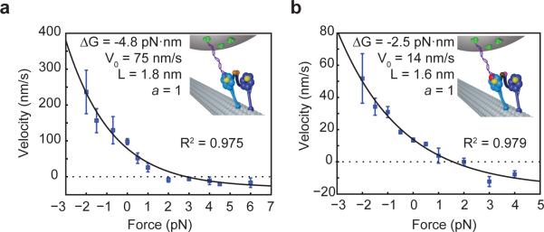
Force-velocity curves for head-tethered WT/WT homodimer (a) and mutant head-tethered AAA1K/A heterodimer (b) at 1 mM ATP are fitted with a one state model in which the backward stepping rate is load independent (black curve). The parameters obtained from the fit are the unloaded velocity V0, the characteristic length L, and the minimum velocity Vmin. Error bars represent S.E.M (Nbeads = 4-10). Velocities at “0 pN force” were obtained from single molecule fluorescence measurements (Nmotor >60).
The asymmetric response of a dynein monomer to load could arise from force-dependent inhibition of a particular step in the ATPase cycle. Alternatively, the interaction between the MTBD and the tubulin binding site may become stronger as force is applied in a particular direction. To distinguish between these possibilities, we repeated F-V measurements using the mutant head-tethered WT/AAA1K/A construct (Fig. 6b). If the force dependence of velocity of the WT head originated from one of the ATPase steps, such as nucleotide binding or hydrolysis, one would expect a different step to become rate-limiting in the AAA1K/A head-tethered construct since this head does not perform an ATP-dependent linker swing12. A novel rate-limiting step would in turn result in a different F-V relationship. We observed that the mutant head-tethered construct exhibited a concave-up F-V curve, similar to WT/WT. The ΔG parameter, which represents the effective energetic bias from ATP hydrolysis per step in our simple model, is almost exactly twice as large in WT/WT (4.8 pN·nm) as it is in the AAA1K/A head-tethered construct (2.5 pN·nm). This is consistent with our observation that constructs with two active heads are able to pull against twice the stall force of mutant heterodimers. Although WT/AAA1K/A is nearly four times slower, the characteristic length L, which determines how rapidly the motor's velocity scales with force, remains nearly identical (1.6 nm) to that of WT/WT (1.8 nm). The results suggest that the different response of forward and backward stepping rates to load arise from the asymmetry of the MT binding interface. It has been shown that the dynein MTBD behaves as a catch bond under load, as hindering forces slow down its ATP-dependent release from the MT21. The characteristic length arising from our F-V curve may thus correspond to a distance by which the head needs to move in order to release the catch bond of the MTBD.
DISCUSSION
Characterizing the behavior of both WT and mutant heads under load allowed us to provide a mechanistic description of the force production by the two heads of a walking dimer. The force is generated mainly in the MT bound state, consistent with the powerstroke model26. Our force measurements set a lower bound for the force produced by a power stroke at 1.5 pN (Fig. 4). This force also constitutes a measurement of the maximal force with which one head can pull on its partner head through linker tension. While the priming stroke of the unbound head has been proposed to push against the MT-tethered head and drive motility towards the MT minus end9, we found that it provides less than 1.5 kBT of directional bias per step and thus cannot account for the mechanical work performed by dynein over one mechanochemical cycle. However, the priming stroke remains vital to dynein's mechanochemical cycle as it is likely to increase the reach of the diffusional step and prime the linker to enable an effective subsequent powerstroke. We demonstrated that a dynein head is able to generate half the stall force of the dimer. Given dynein's flexibility and lack of strict interhead coordination, the heads in a dynein dimer can be thought of as a pair of mechanically coupled monomers as opposed to a single cyclic machine akin to myosin V or kinesin-1. We propose that each of dynein's monomers is capable of independently generating approximately half of the stall force of the dimer, and that each head's force production contributes to the total output of the dimer. We refer to this framework as ‘load-sharing’ between dynein heads to highlight its similarities with the additive forces observed when a cargo is driven by a low number of processive motors27–29.
Our vision of how load sharing may be achieved in cytoplasmic dynein is illustrated in Figure 7.A dynein dimer spends the majority of the time with both heads bound to the MT. Unlike kinesin and myosin, the hindering load is distributed among both heads with their long flexible tails acting as springs (Fig. 7i). When one head releases from the MT, the entire load is transferred to the bound head (Fig. 7ii). The bound head functions as an anchor while the released head performs a diffusional search for a new binding site. During this diffusional search, the tail may briefly move backwards in response to external load, but we expect this motion to be too rapid to be resolvable given the ~3 ms time resolution of our assay. When the stepping head rebinds to MT (Fig. 7iii) and its linker undergoes a power stroke (Fig. 7iv), load is redistributed between the heads. The tail of the leading head becomes more stretched, as this head bears a larger fraction of the total load. Since hindering force significantly decreases the rate at which a dynein head releases from the MT21, the leading head now serves as an anchor while the trailing head becomes more likely to take the subsequent step. Importantly, the work done by the power stroke of each head is stored in the form of linker tension and is applied to bias the subsequent step of the partner head against hindering load. As a result, each step effectively combines the force-generating capacities of the two partner heads, allowing a dynein dimer to work against hindering forces higher than the maximal force produced by each head.
Figure 7. Load-sharing model for dynein force production.
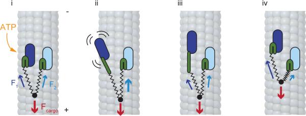
(i) When dynein is in a two-head bound state, the external load (F) is distributed between the two heads due to the elastic nature of the tail (stretched springs) and linker (bent green rods) regions. Because each panel represents an equilibrium state, the sum of the three forces (Fcargo, F1, and F2) is always equal to zero. (ii) ATP binding to the AAA1 site of one head triggers its release from the MT and priming of the linker (straight green rod). As this head diffuses to a new binding site, the external load is transferred in its entirety to the DNA-tethered head (iii) The stepping head rebinds to MT, with the linker still in the primed configuration. (iv) The linker returns to its original state via a powerstroke, the tail moves forward and the load is redistributed between the heads. Load sharing allows a dynein dimer to work against hindering forces larger than the forces that can be produced by a single head.
A distinguishing feature of dynein's motility under load is that the step size and stepping rate of a DNA-tethered head are the same as the size and rate of steps measured when the load is applied to the tail. This unusual finding can be explained by the large and flexible structure of the dynein dimer and tension-dependent changes in dynein's stepping pattern21 (Supplementary Fig. 8). Our findings further distinguish dynein from other cytoskeletal motors and provide new clues for understanding how it functions in vivo. Unlike kinesin-1, which readily releases from the MT at near-stall loads23, the dynein MTBD resists large backwards loads21. This may make dynein ideally suited for transportation of large cellular cargos or sliding of MTs under tension. The heads of a dimer produce force independently and they must be inhibited simultaneously by a regulatory protein to stall dynein movement15,30. A dimer with a single head inhibited would behave similarly to our WT/AAA1K/A heterodimer, slowing down by several fold yet still producing substantial force. Independent force generation can also enable dynein to perform work in unusual environments such as at the ends of MT's or while crosslinking two MTs and sliding them relative to each other31, and can potentially aid the understanding of collective force production by trimeric outer-arm dyneins32. Finally, it has been reported that multiple dyneins combine their efforts more effectively than do multiple kinesins33. The load-sharing mechanism inherent to a single dimer may explain dynein's enhanced ability to pull cargos when working in a team. In a system with multiple motors transporting the same cargo, individual motors experiencing a hindering force will tend to remain attached to the track and prevent the cargo from slipping backwards. Meanwhile, motors that are not subjected to a significant hindering force will have a much higher probability of stepping forward, resulting in self-regulating and efficient minus-end directed transport by multiple motors.
METHODS
Preparation of DNA tethers
Double-stranded DNA tethers labeled with HT ligand (Promega) on one end and biotin on the other were prepared as follows. A biotinylated DNA oligo (5’-/biotin/TTC GGT CAA TAC CCG GCG CAG AGC GCT CAG GCG CGA GGT CAA CAG AGG GCG GAG GGT GGG CCA GCG CGA CCC CG-3’) was hybridized with an amine-modified DNA oligo (5’-/C6 amino/GTG TCG GGG TCG CGC TGG CCC ACC CTC CGC CCT CTG TTG ACC TCG CGC CTG AGC GCT CTG CGC CGG GTA TTG AC-3’) in DNA buffer (20 mM NaHCO3, 50mM KCl, 1.25 mM MgCl2, pH = 8.4) at 90°C for two minutes, followed by incubation at 25°C for 40 minutes. An amine-reactive HT Succinimidyl Ester (O4) ligand (Promega) was then attached to the terminal amine group on the DNA by incubation for 6 hours at room temperature. The reaction was then quenched with 1mM glycine for 10 minutes to remove excess reactive ligand. The resulting tethers were sequentially de-salted into DLB buffer (30 mM HEPES, 2 mM MgCl2, 1 mM EDTA, 10% glycerol, pH 7.2) through two G-25 columns (GE Healthcare). De-salted tethers, at ~25 μM concentration in DLB, were frozen and stored at -20°C. Fluorescently labeled DNA molecules were prepared exactly as described above, except the biotinylated oligo was replaced with a 5’ Cy3-modified oligo with an identical nucleotide sequence.
Protein purification
S. cerevisiae cultures expressing the dynein constructs used in the study were grown to an OD600 of 1.0-1.5. They were then harvested by centrifugation and the pellets were resuspended in ~3mL of water per liter of starting culture. The resuspended pellets were frozen by dripping into liquid nitrogen and lysed by grinding in a commercial stainless steel coffee grinder (KitchenAid; pre-cooled with liquid nitrogen) for ~30 seconds. Following lysis, the ground powder was thawed in a 37°C water bath concurrently with the addition of 0.2 volumes of 5X lysis buffer (150 mM HEPES, 250 mM KAcetate, 10 mM MgAcetate, 5 mM EGTA, 5 mM PMSF, 500μM MgATP, 50% glycerol, pH 7.4). Note that due to their long-term instability in solution, PMSF and MgATP were stored separately and were only added to the stock buffer immediately preceding dynein purification. The resuspended lysis mixture was then centrifuged at 270,000 g for 45 min. The resulting supernatant was mixed with 200 μL of IgG sepharose beads (GE Healthcare Life Sciences) and incubated with rotation at 4°C for 1 hr. The beads were then washed twice with wash buffer (125 mM KCl, 30 mM HEPES, 50mM KAcetate, 2 mM MgAcetate, 1 mM EGTA, 1 mM PMSF, 100 μM MgATP, 10% glycerol, pH 7.4) and washed once with 10 mL of TEV buffer (150 mM KCl, 10 mM Tris-HCl, 10% glycerol, 1 mM TCEP, 1 mM PMSF, 100 μM ATP, pH 8.0). Following the wash, beads were incubated with TEV protease in 500 μL of TEV buffer for at 16°C for 1hr with rotation. The dynein-containing supernatant was then either immediately labeled with DNA tethers or aliquoted and flash-frozen if labeling was not necessary. .
Labeling
After TEV cleavage, dynein was mixed with an excess of de-salted tethers (e.g. 300 μL of 200 nM dynein and 100 μL of 25 μM tether) and nutated at 4°C for 5 hours. At the end of the labeling reaction, the microtubule bind and release (MTBR) protocol was used to remove excess DNA and enrich the population of active motors. For MTBR, freshly prepared microtubules (MT's) were suspended in dynein lysis buffer supplemented with 10 μM taxol (DLB: 30 mM HEPES, 50 mM KAcetate, 2mM MgAcetate, 1mM EGTA, 10% glycerol, pH 7.4) at a concentration of ~2 mg/mL, then added to 5 volumes of ~200 nM dynein and incubated for 7 min at room temperature. The dynein/MT mixture was then layered over 200 μL of sucrose cushion (DLB supplemented with 50% sucrose and 10 μM taxol) in an ultracentrifuge tube (Beckman TLA 120.2) and centrifuged at 54,000 g for 10 min at 23°C. The pellet was washed twice with 200 μL of wash buffer (DLB supplemented with 1 mM DTT and 10 μM taxol) and resuspended in ~200 μL of release buffer (DLB supplemented with 300 mM KCl, 2 mM MgATP, and 500 μM DTT). The resuspended pellet was allowed to incubate in release buffer for 10 min at room temperature and then centrifuged at 54,000 g for 10 min at 23°C. The supernatant of this second centrifugation run contained purified DNA-labeled dynein with excess tethers removed. . Fractions from MTBR purification were then analyzed on a denaturing gel. All dynein constructs used in this study were artificially dimerized with either GST or rapamycin-mediated FKBP– FRB binding (Supplementary Fig. 1). >96% of the GST-dimerized constructs were labeled with a single DNA. For tail-tethered dynein experiments, HT-GST-Dyn1331kD was labeled with a biotinylated HT ligand at the N-terminal HT. The FRB-FKBP pair was used whenever the experiment required heterodimerization between a mutated head and a wild-type (WT) head.
Conjugation of motors to microspeheres
0.9 μm carboxyl latex beads (Life Technologies), were coated with either streptavidin or custom-made rabbit polyclonal αGFP antibodies (Covance) as follows. The beads were washed four times in activation buffer (10 mM MES, 100 mM NaCl, pH 6.0) by vortexing, spinning down at 10,000 RCF for 3 min and resuspending. 1 mg each of EDC and Sulfo-NHS crosslinkers (Pierce Biotechnology), dissolved in 100 μL of DMF, were then added to the beads. The solution was sonicated for ~5 min and vortexed at low speed until visible clumps disappeared. Afterwards, the beads were washed 3 times with coupling buffer (100 mM sodium-phosphate buffer, pH 7.4), mixed with streptavidin or antibodies (at ~1 mg of dry streptavidin or antibody per 100 μL of 4% v/w bead stock) and reacted with shaking at room temperature for 30 min. The labeled beads were then passivated by adding powdered BSA to a final concentration of 10 mg/mL and shaking for 1.5 hrs at room temperature. Passivated beads were washed three times with 1x PBS (Phosphate Buffered Saline, pH 7.4) and stored at 4°C with 0.1% sodium azide and 0.5 mg/mL BSA.
Sample preparation
In FRB/FKBP12 heterodimer experiments, dynein monomers (of which only one was previously labeled with a biotinylated dsDNA tether at the C-terminal HT) were dimerized with 200 nM rapamycin for 10min at room temperature before being diluted to the final concentration and mixed with streptavidin-coated beads. In tail-tethered GST homodimer experiments, dynein dimers were diluted to the final concentration and immediately mixed with either αGFP antibody-coated beads (when working with the GFP-GST-Dyn1331kD-HT construct) or streptavidin-coated beads (when working with the biotinylated HT-GST-Dyn1331kD construct) (Supplementary Fig. 1). The final concentration was determined experimentally for each prep such that no more than 35% of beads exhibited any activity when brought in contact with an axoneme, ensuring that >95% of observed events can be attributed to the actions of single motors34. Dynein was allowed to bind to the beads for 10 min at 4°C before proceeding with sample preparation. The sample chamber was loaded by first flowing Cy5-labeled axonemes in low-salt DLB buffer (30 mM HEPES, 2 mM MgCl2, 1 mM EDTA, 10% glycerol, pH 7.2), waiting 30 seconds for the axonemes to adsorb to the glass surface, then chasing with a solution of dynein-coated beads in motility buffer (assay DLB as specified above with the addition of 35 μg/mL PCD, 2.5 mM PCA, 10 mM DTT, and 1 mg/mL casein, and 1 mM ATP unless specified otherwise). The ends of the sample chamber were then sealed with nail polish to prevent liquid evaporation.
Optical trapping assay
All trapping experiments were performed on a fully automated optical trap, custom-built in an acoustically isolated and temperature-controlled (±0.1°C) room around the body of a Nikon Ti-E inverted microscope. Dynein-coated beads were trapped with a 2W 1064 nm laser (Coherent), tightly focused in the image plane with a 100X 1.49 N.A. apochromat oil-immerision objective (Nikon). The trap was steered with a pair of perpendicular acousto-optical deflectors (AOD's, AA Opto-Electronic), placed in a plane conjugate to the BFP of the objective. Power in the trap was controlled throughout the experiment with a half-wave plate on a motorized rotary mount (New Focus). Position of the bead relatively to the center of the trap was monitored using back-focal plane interferometry, by imaging the back-focal plane of a 1.4 N.A. oil-immersion condenser (Nikon) onto a position-sensitive detector (First Sensor, Inc.) Raw data from the detector were digitized by an NI 9215 analog input module (National Instruments), connected to an NI cRIO-9114 reconfigurable chassis (National Instruments). Signals were acquired and saved to disk at either 5 kHz or 20 kHz, and position feedback was performed at up to 200 Hz using the field-programmable gate array (FPGA) built into the cRIO-9114 chassis. Detector response was calibrated by rapidly raster-scanning the laser across a trapped bead with the AOD's and fitting the resulting curve to a cubic polynomial (Supplementary figure 4c) and trap stiffness was obtained from the Lorentzian fit to the power spectrum of a trapped bead 35.
The temporal resolution of optical trap data is fundamentally limited by the stiffness of the trap, as Brownian noise dominates the recordings at frequencies higher than the corner frequency of the Lorentzian power spectrum. The trap stiffness values used in this work resulted in corner frequencies of up to 400 Hz, corresponding to a temporal resolution of ~ 2.5 ms. Due to the compliance of the dynein motor and the motor-bead linkage, the smallest step size that could be reliably detected by our step-finding algorithm was ~2 nm. The accuracy of position and stiffness calibrations was independently verified by measuring the stall force of kinesin-1 to be 5.6 ± 0.8 pN, in good agreement with previously published values. Axoneme tracks, labeled with Cy5, were excited with a 633nm laser (Coherent), visualized with a monochrome camera (The Imaging Source), and brought to the center of the field of view with a locking XY stage (M-687, Physik Instrumente). The trapped bead was lowered to the surface of the axoneme by moving the trapping objective with a piezo flexure objective scanner (P-721 PIFOC, Physik Instrumente). Only beads that walked for at least 50 nm against the trap were subjected to force feedback and used for further analysis. To minimize noise, the operator controlled the trap remotely throughout the experiment from an adjacent room through software custom-written in LabVIEW 2012 (National Instruments).
TIRF microscopy
Single-molecule motility assays were carried out on a custom-built objective-type TIRF setup, built around the body of a commercial Nikon Ti-E microscope15. Individual dyneins labeled with Cy5-tagged DNA tethers were excited with a 30 mW 633 nm laser (Coherent) and imaged with a 100X 1.49 N.A. apochromat oil-immersion objective (Nikon) onto an iXon EMCCD camera (Andor). Assay preparation was identical to the optical trap sample preparation described in a previous section, except without the addition of latex beads.
Data analysis
Position data were fit to steps using a fully automated, maximum likelihood-based step finding algorithm 36, implemented in Matlab. Because the algorithm assumes white noise with no autocorrelations, data were downsampled to approximately 50% of the corner frequency of the trap prior to fitting. Force-clamp runs that lasted shorter than 1 s, covered less than 50 nm, or included instantaneous jumps larger than 50 nm, were rejected from the analysis; otherwise the output of the step finding algorithm was accepted as is, without any further modifications. Motor velocities were determined by fitting individual runs with a straight line and calculating the slope of the line.
To generate dynein stall force histograms, position data from fixed-trap recordings were downsampled to 500 Hz for ease of visualization and stall events were manually selected. To qualify as a stall, the position trace had to reach a plateau and remain stationary (with mean deviations of less than ± 10nm) for at least half a second before terminating in a ‘rip’. A ‘rip’, indicating that the motor fully released from the MT, had to constitute a rapid (<2 ms) jump of at least 50 nm, larger than the maximum step a dynein molecule can be expected to take. For, the definition of stall was the same except the minimum duration of the plateau at the top of the stall was decreased to 0.1 s, to account for kinesin's faster stepping rate and shorter near-stall dwells.
Force-velocity (F-V) curves were fit to the velocity expression for a one-state motor model25, V(F) = V+e–aFL/KT(1 –eΔG+FL)/KT), where F is the external force, V+ is the unloaded velocity ΔG is the energetic bias provided by ATP hydrolysis, L is a characteristic distance, and a is a dimensionless parameter that defines the partitioning of load-dependence between the forward and backward stepping rates. The net unloaded velocity V0 can be expressed as V0 = V+(1 – eΔG/kT). See Supplementary Note 1 for detailed description of the model.
Supplementary Material
ACKNOWLEDGEMENTS
We are grateful to F.B. Cleary, M.A. Dewitt, J. Bandaria, and C.A. Cypranowska for critical reading of this manuscript. This work was supported by NIH (GM094522 (AY)), NSF CAREER Award (MCB-1055017 (AY)) and NSF Graduate Research Fellowship (DGE 1106400 (VB)).
Footnotes
AUTHOR CONTRIBUTIONS
V.B. and A.Y. designed experiments; V.B. performed the biochemical experiments; V.B., N.H., and A.C. performed optical trapping assays, V.B., N.H. and A.C. analyzed the data, and V.B. and A.Y. wrote the manuscript.
SUPPLEMENTARY INFORMATION
Supplementary information is linked to in the online version of this paper.
COMPETING FINANCIAL INTERESTS
The authors declare no competing financial interests.
REFERENCES
- 1.Mallik R, Carter BC, Lex SA, King SJ, Gross SP. Cytoplasmic dynein functions as a gear in response to load. Nature. 2004;427:649–52. doi: 10.1038/nature02293. [DOI] [PubMed] [Google Scholar]
- 2.Gennerich A, Carter AP, Reck-Peterson SL, Vale RD. Force-induced bidirectional stepping of cytoplasmic dynein. Cell. 2007;131:952–65. doi: 10.1016/j.cell.2007.10.016. [DOI] [PMC free article] [PubMed] [Google Scholar]
- 3.Roberts AJ, Kon T, Knight PJ, Sutoh K, Burgess SA. Functions and mechanics of dynein motor proteins. Nat. Rev. Mol. Cell Biol. 2013;14:713–26. doi: 10.1038/nrm3667. [DOI] [PMC free article] [PubMed] [Google Scholar]
- 4.Kardon JR, Vale RD. Regulators of the cytoplasmic dynein motor. Nat. Rev. Mol. Cell Biol. 2009;10:854–65. doi: 10.1038/nrm2804. [DOI] [PMC free article] [PubMed] [Google Scholar]
- 5.Carter AP, Cho C, Jin L, Vale RD. Crystal Structure of the Dynein Motor Domain. Science. 2011;331:1159–1165. doi: 10.1126/science.1202393. [DOI] [PMC free article] [PubMed] [Google Scholar]
- 6.Kon T, Sutoh K, Kurisu G. X-ray structure of a functional full-length dynein motor domain. Nat. Struct. Mol. Biol. 2011;18:638–642. doi: 10.1038/nsmb.2074. [DOI] [PubMed] [Google Scholar]
- 7.Höök P, Vallee RB. The dynein family at a glance. J. Cell Sci. 2006;119:4369–71. doi: 10.1242/jcs.03176. [DOI] [PubMed] [Google Scholar]
- 8.Imamula K, Kon T, Ohkura R, Sutoh K. The coordination of cyclic microtubule association/dissociation and tail swing of cytoplasmic dynein. Proc. Natl. Acad. Sci. U. S. A. 2007;104:16134–9. doi: 10.1073/pnas.0702370104. [DOI] [PMC free article] [PubMed] [Google Scholar]
- 9.Roberts AJ, et al. AAA+ Ring and linker swing mechanism in the dynein motor. Cell. 2009;136:485–95. doi: 10.1016/j.cell.2008.11.049. [DOI] [PMC free article] [PubMed] [Google Scholar]
- 10.Kon T, et al. The 2.8 Å crystal structure of the dynein motor domain. Nature. 2012;484:345–50. doi: 10.1038/nature10955. [DOI] [PubMed] [Google Scholar]
- 11.Schmidt H, Gleave ES, Carter AP. Insights into dynein motor domain function from a 3.3-Å crystal structure. Nat. Struct. Mol. Biol. 2012;19:492–7. doi: 10.1038/nsmb.2272. [DOI] [PMC free article] [PubMed] [Google Scholar]
- 12.Kon T, Mogami T, Ohkura R, Nishiura M, Sutoh K. ATP hydrolysis cycle-dependent tail motions in cytoplasmic dynein. Nat. Struct. Mol. Biol. 2005;12:513–9. doi: 10.1038/nsmb930. [DOI] [PubMed] [Google Scholar]
- 13.Roberts AJ, et al. ATP-Driven Remodeling of the Linker Domain in the Dynein Motor. Structure. 2012;20:1670–1680. doi: 10.1016/j.str.2012.07.003. [DOI] [PMC free article] [PubMed] [Google Scholar]
- 14.Guydosh NR, Block SM. Direct observation of the binding state of the kinesin head to the microtubule. Nature. 2009;461:125–8. doi: 10.1038/nature08259. [DOI] [PMC free article] [PubMed] [Google Scholar]
- 15.DeWitt MA, Chang AY, Combs PA, Yildiz A. Cytoplasmic dynein moves through uncoordinated stepping of the AAA+ ring domains. Science. 2012;335:221–5. doi: 10.1126/science.1215804. [DOI] [PMC free article] [PubMed] [Google Scholar]
- 16.Qiu W, et al. Dynein achieves processive motion using both stochastic and coordinated stepping. Nat. Struct. Mol. Biol. 2012;19:193–200. doi: 10.1038/nsmb.2205. [DOI] [PMC free article] [PubMed] [Google Scholar]
- 17.Reck-Peterson SL, et al. Single-molecule analysis of dynein processivity and stepping behavior. Cell. 2006;126:335–48. doi: 10.1016/j.cell.2006.05.046. [DOI] [PMC free article] [PubMed] [Google Scholar]
- 18.Lu Y, Weers B, Stellwagen NC. DNA persistence length revisited. Biopolymers. 2002;61:261–75. doi: 10.1002/bip.10151. [DOI] [PubMed] [Google Scholar]
- 19.Coy D, Wagenbach M, Howard J. Kinesin takes one 8-nm step for each ATP that it hydrolyzes. J. Biol. Chem. 1999;274:3667–3671. doi: 10.1074/jbc.274.6.3667. [DOI] [PubMed] [Google Scholar]
- 20.Kon T, Nishiura M, Ohkura R, Toyoshima YY, Sutoh K. Distinct functions of nucleotide-binding/hydrolysis sites in the four AAA modules of cytoplasmic dynein. Biochemistry. 2004;43:11266–74. doi: 10.1021/bi048985a. [DOI] [PubMed] [Google Scholar]
- 21.Cleary FB, et al. Tension on the linker gates the ATP-dependent release of dynein from microtubules. Nat. Commun. 2014;5:4587. doi: 10.1038/ncomms5587. [DOI] [PMC free article] [PubMed] [Google Scholar]
- 22.Cho C, Reck-Peterson SL, Vale RD. Regulatory ATPase sites of cytoplasmic dynein affect processivity and force generation. J. Biol. Chem. 2008;283:25839–45. doi: 10.1074/jbc.M802951200. [DOI] [PMC free article] [PubMed] [Google Scholar]
- 23.Visscher K, Schnitzer MJ, Block SM. Single kinesin molecules studied with a molecular force clamp. Nature. 1999;400:184–9. doi: 10.1038/22146. [DOI] [PubMed] [Google Scholar]
- 24.Gibbons IR, et al. The affinity of the dynein microtubule-binding domain is modulated by the conformation of its coiled-coil stalk. J. Biol. Chem. 2005;280:23960–5. doi: 10.1074/jbc.M501636200. [DOI] [PMC free article] [PubMed] [Google Scholar]
- 25.Thomas N, Imafuku Y, Tawada K. Molecular motors: thermodynamics and the random walk. Proc. R. Soc. B. 2001;268:2113–22. doi: 10.1098/rspb.2001.1764. [DOI] [PMC free article] [PubMed] [Google Scholar]
- 26.Burgess S. a, Walker ML, Sakakibara H, Knight PJ, Oiwa K. Dynein structure and power stroke. Nature. 2003;421:715–8. doi: 10.1038/nature01377. [DOI] [PubMed] [Google Scholar]
- 27.Hendricks AG, Holzbaur ELF, Goldman YE. Force measurements on cargoes in living cells reveal collective dynamics of microtubule motors. Proc. Natl. Acad. Sci. U. S. A. 2012;2012:1–6. doi: 10.1073/pnas.1215462109. [DOI] [PMC free article] [PubMed] [Google Scholar]
- 28.Rai AK, Rai A, Ramaiya AJ, Jha R, Mallik R. Molecular adaptations allow dynein to generate large collective forces inside cells. Cell. 2013;152:172–82. doi: 10.1016/j.cell.2012.11.044. [DOI] [PubMed] [Google Scholar]
- 29.Kunwar A, Mogilner A. Robust transport by multiple motors with nonlinear force-velocity relations and stochastic load sharing. Phys. Biol. 2010;7:16012. doi: 10.1088/1478-3975/7/1/016012. [DOI] [PMC free article] [PubMed] [Google Scholar]
- 30.Huang J, Roberts AJ, Leschziner AE, Reck-Peterson SL. Lis1 Acts as a “Clutch” between the ATPase and Microtubule-Binding Domains of the Dynein Motor. Cell. 2012;150:975–86. doi: 10.1016/j.cell.2012.07.022. [DOI] [PMC free article] [PubMed] [Google Scholar]
- 31.Tanenbaum ME, Vale RD, McKenney RJ. Cytoplasmic dynein crosslinks and slides anti-parallel microtubules using its two motor domains. Elife. 2013;2:e00943. doi: 10.7554/eLife.00943. [DOI] [PMC free article] [PubMed] [Google Scholar]
- 32.Hirakawa E, Higuchi H, Toyoshima YY. Processive movement of single 22S dynein molecules occurs only at low ATP concentrations. Proc. Natl. Acad. Sci. U. S. A. 2000;97:2533–7. doi: 10.1073/pnas.050585297. [DOI] [PMC free article] [PubMed] [Google Scholar]
- 33.Derr ND, et al. Tug-of-War in Motor Protein Ensembles Revealed with a Programmable DNA Origami Scaffold. Science. 2012;338:662–665. doi: 10.1126/science.1226734. [DOI] [PMC free article] [PubMed] [Google Scholar]
- 34.Svoboda K, Block SM. Force and velocity measured for single kinesin molecules. Cell. 1994;77:773–84. doi: 10.1016/0092-8674(94)90060-4. [DOI] [PubMed] [Google Scholar]
- 35.Neuman KC, Block SM. Optical trapping. Rev. Sci. Instrum. 2004;75:2787–809. doi: 10.1063/1.1785844. [DOI] [PMC free article] [PubMed] [Google Scholar]
- 36.Kalafut B, Visscher K. An objective, model-independent method for detection of non uniform steps in noisy signals. Comput. Phys. Commun. 2008;179:716–723. [Google Scholar]
Associated Data
This section collects any data citations, data availability statements, or supplementary materials included in this article.