Abstract
Present day cortical brain machine interfaces (BMI) have made impressive advances using decoded brain signals to control extracorporeal devices. Although BMIs are used in a closed-loop fashion, sensory feedback typically is visual only. However medical case studies have shown that the loss of somesthesis in a limb greatly reduces the agility of the limb even when visual feedback is available (for review see Robles-De-La-Torre, 2006). To overcome this limitation, this study tested a closed-loop BMI that utilizes intracortical microstimulation (ICMS) to provide ‘tactile’ sensation to a non-human primate (NHP). Using stimulation electrodes in Brodmann area 1 of somatosensory cortex (BA1) and recording electrodes in the anterior intraparietal area (AIP), the parietal reach region (PRR) and dorsal area 5 (area 5d), it was found that this form of feedback can be used in BMI tasks.
Keywords: Brain machine interface, Neural prosthesis, Stimulation, Macaque, Microelectrodes, Parietal cortex, Somatosensory cortex
Introduction
During the last decade, considerable progress has been made in research on upper extremity cortical neuroprostheses. Different cortical areas have been utilized as sources for providing control signals for neuroprosthetics which typically control computer cursors or robotic limbs. For these neuroprosthetic applications, neural signals can be recorded from motor cortex to provide continuous control of trajectories (Serruya, Hatsopoulos et al. 2002; Taylor, Tillery et al. 2002; Carmena, Lebedev et al. 2003; Santhanam, Ryu et al. 2006). More cognitive neural signals can be extracted from posterior parietal cortex (PPC) to provide both goal and trajectory information (Musallam, Corneil et al. 2004; Hwang and Andersen 2009; Hauschild, Mulliken et al. 2012; Hwang and Andersen 2012). However, most neural prosthetics research has focused on closed-loop control in which vision is the feedback signal to the subject for computer cursors (Serruya, Hatsopoulos et al. 2002; Taylor, Tillery et al. 2002; Hochberg, Serruya et al. 2006; Kim, Simeral et al. 2007; Kim, Simeral et al. 2008; Truccolo, Friehs et al. 2008; Kim, Simeral et al. 2011; Simeral, Kim et al. 2011) and robotic devices (Wessberg, Stambaugh et al. 2000; Carmena, Lebedev et al. 2003; Aaron, Herr et al. 2006; Velliste, Perel et al. 2008; Hochberg, Bacher et al. 2012). The almost complete absence of somesthetic information provided by current upper extremity prostheses severely limits their usability, particularly for the on-line control of robotic hands for grasping and object manipulation (Fagg, Hatsopoulos et al. 2007; Johansson and Flanagan 2009; Lebedev, Tate et al. 2011).
One approach for providing missing information from the prosthetic’s contact with objects is sensory substitution whereby an intact sensory system such as vision, hearing or cutaneous sensation elsewhere on the body is used as an input channel for information related to the prosthesis (Riso 1999). But none of these sensations feels natural and subjects must learn to translate and utilize input that is not direct (Marasco, Kim et al. 2011). For amputee subjects, natural sensation of missing limbs can be provided by stimulating peripheral afferent nerves in the limb’s stump with intrafascicular electrodes (Dhillon and Horch 2005; Horch, Meek et al. 2011) or cuff-like electrodes (Tyler and Durand 2002). For subjects who have had targeted reinnervation surgery, sensation of the limb can be provided by touching the part of the skin which is reinnervated as a consequence of surgically redirecting nerves that once served the lost limb (Kuiken, Marasco et al. 2007). However, none of these techniques will work for quadriplegic patients who have damage at a high level of the spinal cord. A plausible alternative is to directly stimulate the neurons in the corresponding intact somatosensory cortex which normally receive sensory signals from the limb. This stimulation is direct in the sense that sensors on the robotic limb provide input to topographically matching locations in the somatotopic map in cortex, with primary somatosensory cortex (S1) being a suitable target (Libet 1982; Ojemann and Silbergeld 1995).
Studies have demonstrated that somatosensory percepts can be elicited by both epicortical stimulation (Penfield and Boldrey 1937; Penfield and Rasmussen 1950; Penfield and Jasper 1954; Libet 1982; Richer, Martinez et al. 1993; Ojemann and Silbergeld 1995) or intracortical microstimulation (ICMS) (Romo, Hernandez et al. 1998; Romo, Hernández et al. 2000; Fitzsimmons, Drake et al. 2007; O’Doherty, Lebedev et al. 2009; O’Doherty, Lebedev et al. 2011; O’Doherty, Lebedev et al. 2012). Compared to epicortical stimulation, ICMS provides a more viable option for restoring sensory capacities. ICMS employs penetrating microelectrodes which produce more punctate activation than surface contact electrodes (Cogan 2008). Microelectrode arrays can be chronically implanted into the cortex and stay functional for a long period of time (Hathaway and McKinley 1989; Rousche and Normann 1999; Santhanam, Ryu et al. 2006; Parker, Davis et al. 2011; Torab, Davis et al. 2011; Berg, Dammann et al. 2013). Also, as mentioned above, using microelectrodes allows stimulation of a small volume of tissue, which should, with a sufficient number of electrodes, improve the selectivity and spatial resolution of functional responses compared to macroelectrode alternatives.
Two groups of scientists have demonstrated preliminary evidence of ICMS in NHPs being useful for providing somatosensory feedback for an upper limb neuroprosthetic. Nicolelis and his colleagues reported the operation of a bidirectional BMI that provided artificial tactile feedback to rhesus monkeys through ICMS of S1 (O’Doherty, Lebedev et al. 2011). In that study, control signals were derived from single unit activity recorded from primary motor cortex and were used to control a virtual-reality arm in a 2D environment. Artificial texture of different objects was conveyed to the animal via different ICMS patterns which were found to facilitate perception and minimize the detrimental effect of stimulation artifact on recorded brain signals. The results of two studies from Bensmaia’s group showed ICMS pattern could be precisely tuned to provide somatosensory feedback in an intuitive way (Hathaway and McKinley 1989; Berg, Dammann et al. 2013). One study implemented a somatosensory prosthesis which could intuitively convey information about contact force to the subject (Berg, Dammann et al. 2013). The other study developed approaches to intuitively convey information about contact location, pressure, and timing through ICMS (Hathaway and McKinley 1989). Both studies provided the evidence that sensory experience induced by ICMS was comparable to that caused by mechanical stimuli.
Here we present data from a study designed to show that tactile sensation of a virtual prosthetic limb can be fed back to a non-human primate subject to guide the movement of a virtual prosthetic limb via ICMS in Brodmann’s area 1 (BA1) of primary somatosensory cortex. We tested the somatosensory feedback in scenarios in which vision was either not helpful or was only partially helpful for performing a task. We also compared performance of tasks using somatosensory feedback versus tasks using auditory feedback as a sensory substitute. Additionally, we explored the possibility of closing the loop for the cortical neuroprosthesis by coupling stimulation evoked somatosensory feedback with real-time brain control of the prosthetic limb. In this case, high-level cognitive signals from the PPC (Musallam, Corneil et al. 2004) were employed as control signals for the virtual prosthetic limb. Our previous work in PPC showed brain control with spiking data (Hauschild, Mulliken et al. 2012). This current study for the first time adds stimulation feedback and also uses broadband multiunit activity for brain control. This study demonstrates that the movement of a virtual prosthetic limb can be controlled by signals recorded from PPC while ICMS artifacts are filtered out.
Methods
Approvals
We obtained approval for the animal use protocol in this study from the Caltech Institutional Animal Care and Use Committee. All experimental procedures are in compliance with the guidelines of the National Institutes of Health Guide for the Care and Use of Laboratory Animals.
Prosthetic system with a somatosensory feedback loop
We developed a neural prosthetic system consisting of a motion tracking system, cortically implanted electrode arrays, a neural data processing system, a neurostimulation system, and a virtual modular prosthetic limb (vMPL) which runs in a 3D virtual reality environment (VRE) (Figure 1). All tasks were designed in the VRE environment and were presented to the animal in stereoscopic 3D via shutter glasses. The monkey controlled the vMPL either by motion of his own right limb through a motion tracking system (trakSTAR, Ascension Technology Corporation, Milton, VT) or by decoded brain signals through a neural data processing system (indicated by the dashed arrow in Figure 1). Specific circumstances determined by the task (e.g. the virtual hand touching a target object) triggered the neurostimulation system to stimulate the monkey’s somatosensory cortex (S1). The monkey used the system in a total of 119 study sessions (over a period of 13 months). The components of this system are described in detail in the following sections.
Figure 1.
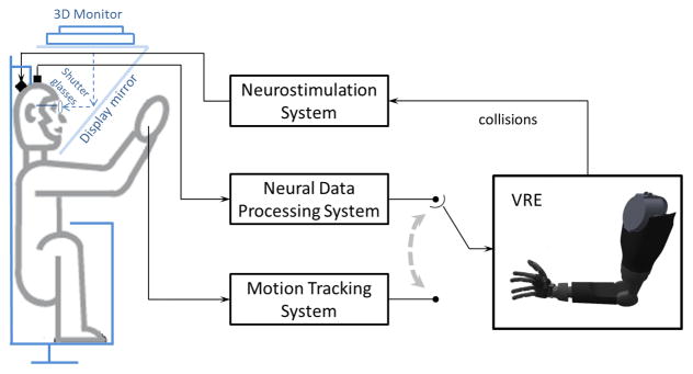
Schematic diagram of the neural prosthetic system. Collisions of target objects and the virtual hand in the VRE triggered the neurostimulation system to stimulate the monkey’s somatosensory cortex. The prosthetic limb was driven by either neural data or motion tracking data depending on the task.
Implantation of electrode arrays
One Utah electrode array (UEA) (CerePort Array, Blackrock Microsystems, Salt Lake City, UT) was implanted in S1 and used to convey electrical stimulation currents generated by the neurostimulation system for somatosensory feedback. The UEA array consists of 100 microelectrodes (1.5 mm in length) arranged in a 10 × 10 grid on a 4 mm × 4 mm silicon base that is 0.25 mm thick. Each microelectrode is insulated with Parylene-C polymer and is electrically isolated from neighboring electrodes by non-conducting glass. Each microelectrode has a tip that is coated with sputtered iridium oxide film (SIROF), allowing for stable neural recordings as well as electrical stimulation. Of the 100 electrodes, 96 are wire bonded using 25 μm gold alloy insulated wires collectively sealed with a silicone elastomer. The wire bundle is potted to a printed circuit board with epoxy, the printed circuit board is inserted into the Patient Pedestal (percutaneous connector), and then the Patient Pedestal is filled with silicone elastomer. Two fine platinum reference wires are also attached to the Patient Pedestal.
Four microwire-based electrode arrays (Floating Microelectrode Arrays (FMA); MicroProbes for Life Sciences, Gaithersburg, MD) were chronically implanted in the PPC to record neural activity from cortical neurons. Neural data were then transmitted to the neural data processing system where they were processed to decode movement intentions. The FMAs (Figure 2) each contain 34 microwire electrodes (1.4–7.1 mm in length) uniformly arranged in a 4 mm × 1.8 mm alumina ceramic base that is < 0.9 mm thick. 32 of these electrodes are used for recording and the remaining two provide a within-array reference. Each microwire recording electrode is insulated with Parylene-C while each reference electrode is uninsulated. All 34 electrodes are bonded to Omnetics connectors housed within a titanium percutaneous connector using Parylene-C polymer insulated 25 μm gold wires that are collectively sealed within a silicone elastomer. The Omnetics connectors are affixed to an in-house designed Percutaneous Connector with epoxy and the Percutaneous Connector is sealed with silicone elastomer. The FMA pedestal is designed and manufactured to be biocompatible (titanium/silicone base, small circumference wound margin, and rounded legs with flush mounted screws) (Huang, Pang et al. 2008).
Figure 2.
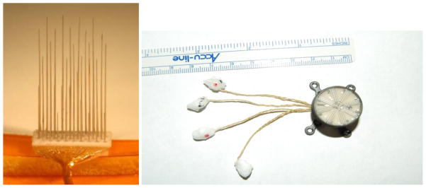
Side view of a 32 channel FMA array (Left) and a 128 channel percutaneous connector which can connect to up to four FMA arrays (Right). The arrays on the right are embedded in low temperature wax that is melted away prior to insertion.
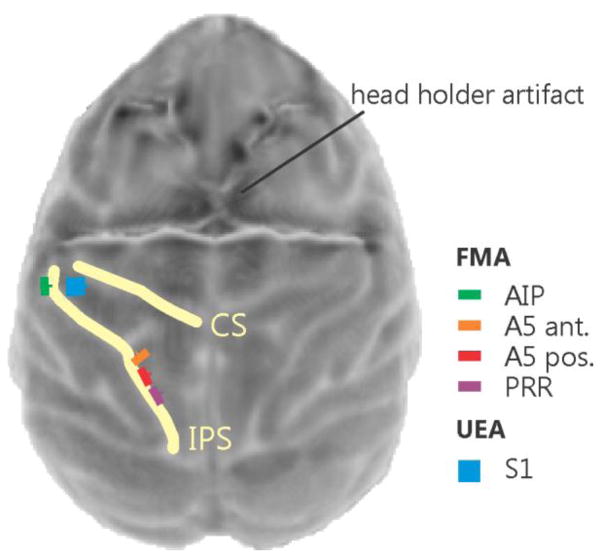
Aseptic surgery was performed according to Caltech-approved IACUC protocols. A biocompatible titanium head holder (Gray Matter Research, LLC) for stabilizing the head was initially affixed to the skull prior to the array placement (Adams, Economides et al. 2007). One UEA array and four FMA arrays were then implanted stereotaxically using pre-surgery anatomical magnetic resonance imaging (MRI) scans to guide the implantation (Figure 3). Two percutaneous connectors, one for stimulation and one for recording, were affixed to the skull with bone screws and acrylic. The UEA array was implanted in the hand representation of Brodmann’s area 1 located in S1. The four FMA arrays were implanted in PPC (two in area 5, one in parietal reach region (PRR) and one in the anterior intraparietal area (AIP)). The UEA array was inserted with a pneumatic inserter (Blackrock Microsystems, Salt Lake City, UT). The FMA arrays are inserted using a custom, vacuum based stereotaxic inserter (Rizzuto, Musallam et al. 2006).
Figure 3.
Top view surface reconstruction of an MRI image of the monkey cortex with superimposed planned array placements. The yellow lines indicate the central sulcus (CS) and intraparietal sulcus (IPS). The image was obtained after head holder implantation (a strong distortion artifact of the four legged head holder can be seen in the top half of the image) but before array placement.
Receptive field mapping
During the first days post implantation we determined which UEA electrodes would be used for stimulation via an initial mapping procedure. We mapped the sensory receptive fields of the multiunits recorded from each electrode. Mapping was done manually while the animal was awake. The animal was trained to remain still while we manipulated his extremities and gave him liquid reward in regular intervals. The animal’s hand was systematically probed with a cotton swab while the multi-unit activity on each electrode was observed to determine the respective receptive fields (Figure 4). If a recorded multiunit was modulated while we were probing the hand (i.e. brushing and poking) we narrowed down the probing area. All multiunits we characterized increased their firing rate when their receptive field on the skin surface was touched. We noted specificity for individual fingers and the palm but used the part of the hand which elicited the strongest response for coloring purposes in Figure 4.
Figure 4.
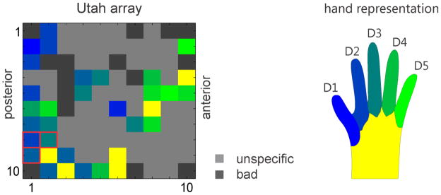
Somatosensory map of the receptive field locations for the UEA array. Electrode locations were colored differently according to the positions on the monkey’s hand that elicited the strongest response when touched (left). Light grey squares indicate unspecific activity not related to touching the hand and dark grey are electrodes that were considered not usable because of impedance measures being out of specification (note that the electrodes in the four corners were reference electrodes). For most of the stimulation experiments we used the 3 red framed electrodes in the bottom left of the diagram. Corresponding locations on the monkey’s hand (right).
Neurostimulation system
A neurostimulation system was used to generate stimulation currents which were delivered through the UEA. The system consists of a neurostimulator (CereStim 96, Blackrock Microsystems, Inc., Salt Lake City, UT), a control switch (CereStim Switch, Blackrock Microsystems, Inc., Salt Lake City, UT), and a control PC. The neurostimulator is a 96-channel programmable current generator equipped with 3 current generator modules (0–215 μA output current range; ±3.5 to ±9.5 output voltage range; 4–5154 Hz frequency range). Thus the neurostimulator is capable of producing 3 concurrent stimuli from any three of the 96 channels. These stimuli are biphasic, charge-balanced pulse trains with adjustable timing and magnitude parameters. In all experiments we used biphasic stimulation (cathodic first) with a maximum current never exceeding 100 μA and a maximum frequency of 300 Hz. The control switch is designed to switch between stimulation and recording modes and was only used in stimulation mode for this study. When in stimulation mode, the control switch passes currents from the neurostimulator to the Utah electrode array. The control PC sends signals to the neurostimulator to configure, start and stop stimulation.
Neural data processing system
Neural data recorded from the FMA arrays was processed via the neural data processing system which used a Cerebus 128 channel Neural Signal Processor (Blackrock Microsystems, Inc., Salt Lake City, UT) and a PC for decoding. The Neural Signal Processor acquires incoming data at 30 kHz with 16-bit resolution and transmits the data to the decode PC. The decode PC processes and decodes neural signals in near real time to provide direct control of the vMPL arm.
vMPL
The virtual Modular Prosthetic limb (vMPL) is a virtual replica of a physical robotic arm (Modular Prosthetic Limb; MPL). Both the virtual and real MPLs were developed by the Applied Physics Laboratory at John Hopkins University (JHUAPL, Laurel, MD). The vMPL is intended to closely resemble a real human adult’s upper arm and has 17 degrees of freedom for joints extending from shoulder to individual fingers, which allows it to perform complex reach movements and dexterous manipulations in 3D. For this study we did not use the full flexibility of the vMPL, but restricted it to an ‘endpoint’ control mode. In this mode only the 3 degrees of freedom which control the position of the center of the palm of the hand are used to move the arm in 3D Cartesian space. In all experiments the monkey was restricted to control the endpoint and not the hand posture or individual fingers. The hand was shaped to form a fist to make collision detection easy and consistent. Control of the arm was either achieved by tracking the monkey’s hand position or by the output of a software decoder which used the recorded brain signals to predict the intended movements of the monkey. The vMPL was displayed using Unity 3D (Unity Technologies, San Francisco, CA) on a separate display PC.
Behavioral Task
Experimental Apparatus
A male macaque monkey was trained to make arm movements within a computer-generated, 3D virtual environment. A schematic of the experimental apparatus is shown in Figure 1. In all experiments, the primate was seated upright in a plastic primate chair with head constrained to the chair via a skull-mounted head holder (Gray Matter Research, LLC). Vision of the animal’s real arm was blocked by a mirror which projected the virtual environment displayed on a top mounted monitor to the monkeys’ eyes. The monkey wore shutter glasses (NVIDIA, custom modified) which allowed each eye to see only its corresponding image of the scene to create the illusion of a stereoscopic 3 dimensional image.
The behavioral task was implemented as a Simulink model (The Mathworks Inc., Natick, MA) and executed on a PC running a real-time OS (xPC, The Mathwork Inc., Natick, MA). The custom program created experimental flow logic to control the state of the virtual reality environment. It monitored all behavioral events, delivered reward, controlled the timing for displaying virtual targets and the vMPL on the display PC, determined target-vMPL collision and triggered a custom C++ program in the neurostimulation system to start stimulation.
Task description
Handbag task
The “handbag” task was designed to examine whether ICMS could be used as an additional feedback channel. The task starts with the presentation of a blue center target (CT) which is manifested as a cube of edge length 3 cm in front of a gray screen (“handbag”) 34 cm horizontal and 30 cm vertical on the display. The monkey had to align the vMPL with the CT and keep touching it for one second to initialize the task. The CT then disappeared and a target (T1) of the same size was randomly presented at one of four possible locations in a plane 3 cm behind the handbag (arranged on an 8.5 cm by 7.5 cm rectangle) and therefore invisible to the monkey. The monkey then had to move the vMPL into the handbag (as shown in Figure 5 top row) and search for the target. When found, the vMPL’s hand had to touch T1 for 1 second to indicate that he found it. T1 had to be acquired within 12 seconds after task initialization. The time limit for this task was determined empirically during the training phase. We had to make sure that it was long enough to allow for a sufficient high success rate in the control condition (see below) and to keep the monkey motivated to perform the task. If the target was acquired and held for one second within that time the monkey received a liquid (water) reward. The monkey controlled the vMPL via motion tracking (Figure 1). To assess the benefit of this channel we used four different task conditions which provided different types of feedback information when any of the targets (CT or T1) were touched:
Figure 5.
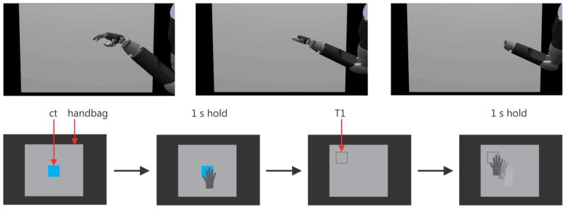
The vMPL reaching into the handbag (image sequence; top row). Schematic task progression (bottom row). After the center target appears (bottom left; blue square; ct) in front of the handbag (grey screen) the vMPL hand has to touch and hold the target for 1s. The center target then disappears and a target appears behind the screen (dotted square; T1) not visible to the monkey. The vMPL then has to reach inside the handbag and probe for the target. When found the target has to be held for 1s.
Control condition
In the control condition, no feedback of any kind was given when a target was touched. In this case the monkey could only solve the task by moving slowly and accidentally staying long enough at the target location. By using this condition as a baseline we could further examine how much each additional channel of information would improve the performance.
Sound condition
When a target was touched a 1000 Hz sine wave sound was played as long as the vMPL’s hand and the target touched. This condition was another control to investigate how effective somatosensory stimulation is versus another sensory modality.
Stim condition
When a target was touched, stimulation was triggered and stayed on as long as the vMPL’s hand touched a target. We stimulated simultaneously on three selected electrodes (Figure 4 left). The stimulus was a 300 Hz biphasic square wave (pulse width 200 μs; phase gap 53 μs) with amplitude of 80 μV. Stimulation parameters and electrode selection were based on the initial mapping and training phase. Only a subspace of all possible combinations of stimulation parameters and electrode selections was tested. Once we evaluated a few robust combinations we did not further investigate others.
Stim+Sound condition
This condition was a combination of the sound and stim conditions in which the sound was played and the stimulation was triggered as long as the vMPL’s hand touched the target.
Match-to-sample task
The match-to-sample task was designed to examine whether ICMS could provide other information besides contact. In this task, the animal was required to identify one of two objects in the handbag based on their stimulation frequency (Figure 6). As in the handbag task, the vMPL was controlled via motion tracking. The center target in this version of the task served as a template and elicited one of two possible stimulation frequencies, 150 or 300 Hz, when touched. All other stimulation parameters were identical to those in the handbag task. At the beginning of each trial, the center target was presented in front of the handbag, as in the handbag task. Touching and holding the CT for one second initialized the task. The CT disappeared and two target objects (Figure 6; T1 and T2) were placed within the handbag at two different locations out of four. If touched, one elicited a 150 Hz stimulation and the other a 300 Hz stimulation. The task of the monkey was now to probe the targets by searching and touching them with the vMPL’s hand and then to hold the one matching the frequency of the CT for one second. Each of the two targets randomly appeared in a different location selected from the four corners of a square in a plane behind the screen. If the monkey held at the wrong target for one second or he could not find and hold at the correct target within 18 seconds, the trial was aborted and the monkey was not given a liquid reward. The additional time needed for probing was taken into account by using the longer time-out period of 18 seconds.
Figure 6.

Schematic task progression for the match-to-sample task. The central target appeared (ct) and when the vMPL touched it a sample ICMS stimulus was applied (either 150 or 300 Hz). After holding the ct for 1 s it disappeared and two targets (dotted squares T1 and T2) were positioned within the handbag. If touched one would trigger ICMS with 150 or 300 Hz. The monkey then had to find, touch and hold the correct target, i.e. the target which would elicit the same stimulus as the ct.
Brain control task
The brain control task was a simplified version of the match-to-sample task in which the vMPL was controlled using decoded brain signals from the PPC. No handbag was used and the animal could see all the targets in the virtual reality environment. The trial was initiated by the vMPL’s hand touching the center target for one second, like in the handbag task. Touching the CT elicited ICMS just as in the handbag ‘stim’ task (300 Hz; all other stimulation parameters were the same as in the handbag task). After the CT disappeared two identical yellow target cubes (Figure 7; T1 and T2) were shown at two locations (not four as in the handbag task) left and right of the CT in a vertical plane 6 cm behind the CT. The location of the two targets was randomly picked from trial to trial. Only T1 elicited ICMS when it was touched by the vMPL’s hand and T2 was a distractor. A timeout similar to the match-to-sample task was enforced here. If T1 was touched and held for one second within a timeout of 18 seconds, the trial was counted as successful and the monkey received liquid reward. If instead T2 was touched for one second, or the timeout was reached, the trial was aborted.
Figure 7.

Schematic task progression for the brain control task. The main difference in this task compared to the previous ones is that the monkey’s decoded brain signals were used to control the vMPL in this task instead of motion tracking. A central target appeared (ct) and the vMPL had to touch and hold it for 1 second. Then two identical looking yellow targets (T1 and T2) appeared in a plane behind the ct. When touched only T1 elicited ICMS (300 Hz). T2 was a distractor which did not elicit stimulation. T1 and T2 were randomly positioned on each trial (T1 left, T2 right or T1 right, T2 left).
Decoding methods paired with stimulation artifact removal
Kalman filter based decoding algorithm
A standard discrete linear Kalman filter was used for continuous online neural decoding for the brain control task (Wu, Gao et al. 2006; Gilja, Nuyujukian et al. 2012; Hauschild, Mulliken et al. 2012). The Kalman filter provides an efficient recursive method for estimating system state in real-time. The current system state was dependent on both the previous system state and system observation. In our study, the system state was defined as the kinematic state of the vMPL hand which included position, velocity and acceleration in three dimensions. In order to accommodate lack of apparent single unit activity (< 3 stable units), the system observation was defined as the measurement of multiunit activity (MUA). We manually selected 29 channels out of the 128 FMA channels based on signal quality (13 from the PRR array, 6 from the AIP array and 10 from the posterior area 5 array). For each channel we calculated the mean power in three high frequency bands (300–2000 Hz, 2000–4000 Hz, 4000–6000 Hz). Thus a total of 87 neural features were used for decoding. Both the evolving system state and the relation to neural observation were approximated by a linear Gaussian model which provides an estimate of uncertainty and the coefficients which were readily learned from training data using a closed form solution based on Bayesian inference (Wu, Gao et al. 2006). The discrete time interval between successive states (time bin size) was chosen to be 50 ms based on values reported in the literature (Cunningham, Nuyujukian et al. 2011; Gilja, Nuyujukian et al. 2012). Since neural activity was usually considered to precede hand movement, a uniform time lag of 100 ms was introduced between neural activity and hand kinematics.
Stimulation artifact removal
Retaining spectral features
ICMS delivered through the UEA is picked up by the FMA recording electrodes despite the physical distance between the electrodes. Because the stimulation artifact contaminates the recording, it must be removed before decoding. We used a simple filtering method for online artifact removal which was designed to work with power spectrum based features derived from MUA activity. ICMS has a different influence on each recording channel in terms of shape and amplitude of the artifact, but possesses the same temporal pattern. We used this property to detect the beginning and end of the stimulation period by focusing on one “reference channel” which showed the largest and therefore easiest to identify artifact. We dealt with the stimulation artifact on the feature level to reduce the computational load for the on-line brain control task.
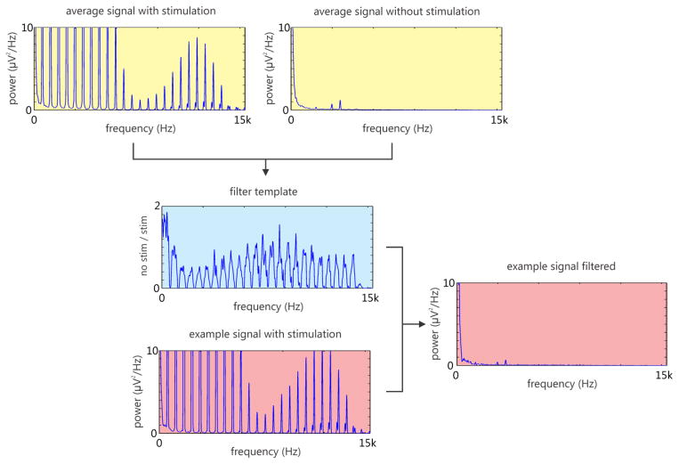
The artifact-removal filter was calculated at the beginning of each session from a five-second interval containing both stimulation and non-stimulation periods. The sample data were divided into 50-ms bins, and the power spectrum of each bin was calculated. The filter was constructed as the ratio of the power spectrum averaged over all non-stimulation time bins to the power spectrum averaged over all stimulation time bins. Then, during online decoding, this filter was applied to the power spectrum of each channel prior to calculating the averaged spectral power features. Figure 8 illustrates an example of averaged power spectrum for non-stimulation time bins, stimulation time bins, and the resulting filter spectrum.
Figure 8.
Example of spectral filter generation from one channel (5 second interval; Channel 16; recording 20130403). The averaged power spectrum for stimulation (yellow; top left) and non-stimulation time bins (yellow; top right) is used to generate a filter template (blue; center). This filter is then used to remove artifacts in future instances (red; bottom left), which leads to a cleaned signal (red; right). Note that the three distinct peaks at 2400, 3000 and 3600 Hz in the averaged non-stimulation spectrum (yellow; top right) and filtered signal (red; right) are artifacts from the motion tracking system which are present continuously and therefore are not filtered out.
Retaining spike features
A new method was also developed to retain spike features offline when there is a stimulation artifact. We made the assumption that the stimulation artifact present in a certain recording channel is nearly deterministic for fixed stimulation parameters, and so the exact shape and size of stimulation artifact waveform could be modeled and used to build a template for that channel. The stimulation artifact could then be rejected by subtracting the template from the signal. To obtain the artifact template, we identified stimulation artifact waveforms in the band pass filtered signal (300 – 6000Hz). The template was then derived by averaging across artifact waveforms. Figure 9 shows the result after rejecting the stimulation artifact from one channel. The residue not only retains spikes between stimulation artifact waveforms but also recovers spikes formerly masked by the stimulation artifact. However, we could not test this method online because the monkey had to be explanted due to an infection. Although we did not use spikes for brain control in the current study, this spike-based method will be useful for future brain-control/stimulation studies in which spikes are used for decoding.
Figure 9.
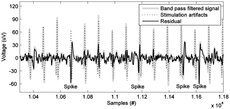
Time series of data before stimulation artifact rejection (gray) and after stimulation artifact rejection (black). The template of stimulation artifact applied is illustrated by dotted line.
Results
Handbag task
The utility of the ICMS-induced somatosensory feedback can be evaluated by the performance achieved in the handbag task. The task was tested for 6 study sessions (excluding training sessions). As shown in Figure 10, we used three metrics to measure the animal’s performance: success rate, average trial duration, and total number of touches before completing a trial. The success rate was determined by the number of successfully completed trials divided by the total number of initiated trials, i.e. trials in which the center target was held for one second. The trial duration was calculated using only successful trials, and was defined as the time from the first center target touch to the successful completion of the trial. The number of touches was defined as the number of times the target (T1) was touched by the vMPL, before a trial was successfully completed (so the minimum number of touches for a successful trial would be one). The “touched” state was determined by the virtual environment’s internal collision detection routines. We considered the performance better when the success rate was higher, trial duration was shorter, and the animal was able to identify target location with fewer touches.
Figure 10.
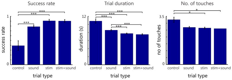
Performance of handbag task measured by success rate (left), trial duration (middle) and number of touches (right) for four sensory feedback conditions. Significant difference according to a one-way ANOVA (Tuckey-Kramer method for multiple comparison correction used) between different task conditions are noted by stars (*=0.05, **=0.01 and ***=0.001 p-value); numbers of trials recorded for the control condition, sound condition, stim condition and stim+sound condition are 281, 1750, 1668 and 858, respectively.
As expected, performance was lowest when no feedback was provided (‘control’ condition) (Figure 10). Although there appeared to be no significant difference of success rate or number of touches between the ‘sound’ condition and the other two feedback conditions, we found it took the animal a significantly longer time to find the target in the handbag using sound alone. There was also no significant difference in number of touches between the ‘control’ and ‘sound’ conditions, but between the stimulation conditions (‘stim’ and ‘stim+sound’) and the ‘control’ condition. The combination of ICMS and sound did not appear to make a significant difference in performance compared with using ICMS alone.
Match-to-sample task
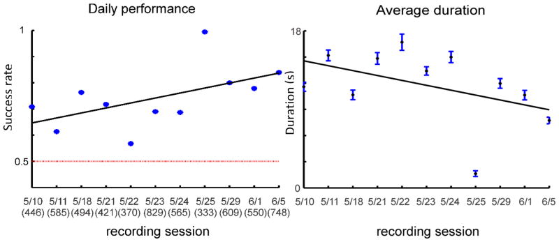
This task was tested exclusively for about one month (11 study sessions; excluding training sessions). We found that the success rate was significantly above chance (average performance 74.17% correct; one sample t test: p=3.88×10⁻⁵), which indicates that most of the time the animal could distinguish between two different ICMS frequencies and use that information to detect different objects. Despite some fluctuations, the animal’s performance improved gradually over the 11 study sessions as demonstrated by the increase in daily success rate and decrease in average duration (Figure 11).
Figure 11.
Daily success rate (left) and average trial duration (right) for match-to-sample task in 11 study sessions
Brain control task
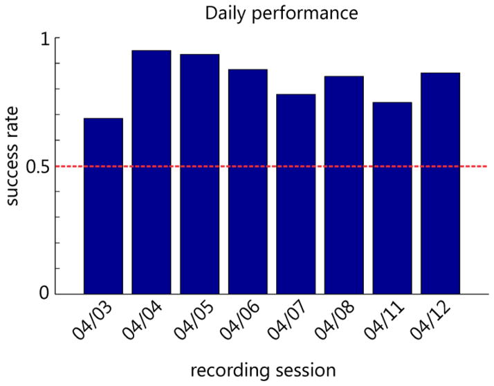
In this task, which was tested for 8 study sessions (excluding training sessions), we combined brain control while ICMS was applied during the course of the task. Successful completion of the task required both the ability to perceive ICMS and the ability to move the vMPL via brain control. Successful decoding was only possible by stimulation artifact removal during ICMS. We initially tried ICMS and online brain control without artifact removal but when ICMS was applied, the vMPL would drift off in a random direction making it difficult for the animal to perform the task. We therefore focused on brain control with artifact removal. The results show that after training the animal was always able to move the vMPL to the correct target with a success rate much higher than chance level (Figure 12). To successfully complete a trial, the monkey had to probe the targets and hold the vMPL on the target if it elicited ICMS or otherwise move towards the other target.
Figure 12.
Daily performance of the animal in the brain control task. Chance level was 50 % since only trials were counted in which one of the two targets was touched for 1 second.
Discussion
In this study, a real time system enabling simultaneous stimulating and decoding from the brain was developed for a closed-loop cognitive neuroprosthesis which could potentially be applied to quadriplegic patients. ICMS was delivered to the hand area of BA1 via chronically implanted microelectrodes. Movement parameters were decoded simultaneously from the posterior parietal cortex to control a virtual modular prosthetic limb. In our model animal, the Rhesus macaque, we demonstrated that percepts can be successfully elicited by ICMS. To overcome the decoding challenges caused by stimulation artifacts, we implemented a frequency filter to effectively remove the stimulation artifacts online. We also developed a method for retaining spike features offline.
Stimulation
Our study demonstrates that ICMS of BA1 can provide useful percepts for closed-loop feedback control. In the handbag task, the subject was able to move the vMPL and use information provided by ICMS to find the object hidden in the handbag. The performance in the handbag task was significantly better when using ICMS feedback as compared to the control condition. In the match-to-sample task, the animal could learn to distinguish between two different stimulation frequencies and associate different frequencies with different objects, which suggests ICMS could potentially convey additional object properties to the brain. Although we cannot tell exactly what kind of percept the different frequencies elicited, the monkey could clearly discriminate them. It is possible that the monkey learned an artificial sensation since researchers have found that the brain can learn a new set of percepts after being exposed to ICMS over time (O’Doherty, Lebedev et al. 2011). It is also possible that ICMS of BA1 may be able to provide close to natural sensations since epicortical acute simulation studies on humans have shown that electrical stimulation of S1 is able to evoke natural, painless percepts (Libet 1982; Ojemann and Silbergeld 1995). Furthermore, researchers have shown that natural signals to the brain can be mimicked if ICMS parameters are precisely tuned (Hathaway and McKinley 1989; Berg, Dammann et al. 2013).
One important factor which can impose constraints on the use of ICMS for neural prosthetic applications is safety. Prolonged ICMS can potentially induce some level of neural injury. Researchers evaluated the histological effects of prolonged ICMS on neural tissue and found that the amount of neuronal loss surrounding the electrode tips was dependent on the stimulation regime applied to the electrodes. (Agnew, Yuen et al. 1986; McCreery, Agnew et al. 1990; McCreery, Pikov et al. 2010). No neurological problems or deterioration in performance was reported for stimulation regimes adopted by most of the animal studies (Rousche and Normann 1999; Santhanam, Ryu et al. 2006; Fitzsimmons, Drake et al. 2007; Parker, Davis et al. 2011; Torab, Davis et al. 2011). A recent study tested sensorimotor consequences of various stimulation regimes on three Rhesus macaques. Except on the first day of stimulation when two ICMS-induced adverse events were reported (vocalization in one NHP and rhythmic contractions of the contralateral arm in both NHPs), no further adverse effects of ICMS were noticed after modifications were made to the stimulation regimes (Chen, Dammann et al. 2014). In the current experiments, no noticeable ICMS-related behavioral deficits were seen during the entire course of the study.
Decoding method
On-line decoding of movement parameters was performed using a simple standard discrete linear Kalman filter. The Kalman filter and its modified versions have been demonstrated to be effective in many off-line reconstruction and on-line continuous brain control studies (Wu, Black et al. 2003; O’Doherty, Lebedev et al. 2011; Hauschild, Mulliken et al. 2012; Hochberg, Bacher et al. 2012). All aforementioned studies utilized single unit activity as control signals. In this study, however, we used MUA as control signals in the brain control task due to lack of apparent and stable single unit activity.. MUA reflects aggregate spiking activity of a number of neurons around electrode tip in a region smaller than LFPs but larger than single units, and reflects energy in high frequencies (300–6000 Hz) (Buchwald and Grover 1970; Legatt, Arezzo et al. 1980). Compared with single-unit spikes, MUA recordings are much easier to obtain and more stable over time. Compared with LFPs, MUAs recorded from neighboring channels are more informative and less redundant. An off-line analysis of single unit, LFP and MUA in premotor cortex has shown that MUA yielded better or equal predictions of reach direction, grasp type and movement velocity and was informative even when spikes were artificially removed (Stark and Abeles 2007). Since our pool of single units was very limited (<3) we had to rely on MUA or LFP (which we initially tried but yielded lower performance than MUA; data not shown).
Stimulation artifact removal
One main challenge for a successful implementation of closed-loop neuroprosthesis is the real-time coupling of ICMS and neural decoding. Neural decoding was performed on neural features from the recording FMAs. However, large stimulation artifacts contaminated data recordings on most channels in the recording arrays. The simplest solution for dealing with stimulation artifacts is to disregard neural recordings during times of stimulation. This method would eliminate the problem altogether but also greatly reduce performance due to lack of control signals during the period of stimulation – notably, at a critical point when the prosthesis is interacting with another object. Another way to reduce the influence of stimulation artifacts is to lower the stimulation frequency or to interleave stimulation and neural recordings with a low clock rate (O’Doherty, Lebedev et al. 2011). Others have tried to fill the gap containing stimulation artifacts by estimating the control signals based on the uncontaminated signals outside the gap (Walter, Murguialday et al. 2012). Here we tried to separate stimulation artifacts from neural signals based on statistical features of both stimulation artifacts and uncontaminated neural signals. The approach utilized information contained in the contaminated signals and performed stimulation artifact removal on the feature level which is well suited for online use due to its simplicity. A method for retaining spike features was also developed off-line and may show promise for online applications.
Future Prospects
The closed-loop system developed in this study could be readily transferred to future human clinical trials for the benefit of quadriplegic patients. Since the vMPL is a virtual replica of a real robotic limb, transition from the virtual reality to a physical implementation is straightforward. The real prosthetic limb has the same appearance and properties as the virtual one and also shares the same control interface. For human subjects, time could be saved due to easier task training: the human can report the qualitative sensation from stimulation and rate the magnitude of effects on percepts when stimulation parameters are changed. By this approach various decoding algorithms could be tested within a relatively short period of time and the control performance could be improved rather quickly. The main challenge for both human and nonhuman primate BMI studies still lies in the ability to obtain a large amount of informative and stable neural signals, which are closely tied to electrode array manufacturing quality and surgical implantation techniques. The demonstration of brain control in the face of stimulation artifacts that relies on MUA is a promising practical step for extending and improving the viability of cortical recordings.
Acknowledgments
We thank K. Pejsa, J.D. Beaty, F.V. Tenore for project management; N. Sammons and C. Gonzales for animal care; V. Shcherbatyuk, Applied Physics Laboratory at John Hopkins University for technical support, T. Yao for administrative assistance; S.J. Bensmaia for valuable advice on stimulation study. This work was supported by the Defense Advanced Research Projects Agency and the National Institutes of Health.
References
- Aaron RK, Herr HM, et al. Horizons in prosthesis development for the restoration of limb function. Journal of the American Academy of Orthopaedic Surgeons. 2006;14(10):S198–S204. doi: 10.5435/00124635-200600001-00043. [DOI] [PubMed] [Google Scholar]
- Adams DL, Economides JR, et al. A biocompatible titanium headpost for stabilizing behaving monkeys. J Neurophysiol. 2007;98(2):993–1001. doi: 10.1152/jn.00102.2007. [DOI] [PubMed] [Google Scholar]
- Agnew W, Yuen T, et al. Histopathologic evaluation of prolonged intracortical electrical stimulation. Exp Neurol. 1986;92(1):162–185. doi: 10.1016/0014-4886(86)90132-9. [DOI] [PubMed] [Google Scholar]
- Berg J, Dammann J, et al. Behavioral Demonstration of a Somatosensory Neuroprosthesis. IEEE transactions on neural systems and rehabilitation engineering: a publication of the IEEE Engineering in Medicine and Biology Society. 2013 doi: 10.1109/TNSRE.2013.2244616. [DOI] [PubMed] [Google Scholar]
- Buchwald JS, Grover FS. Amplitudes of background fast activity characteristic of specific brain sites. J Neurophysiol. 1970;33(1):148–159. doi: 10.1152/jn.1970.33.1.148. [DOI] [PubMed] [Google Scholar]
- Carmena JM, Lebedev MA, et al. Learning to control a brain–machine interface for reaching and grasping by primates. PLoS biology. 2003;1(2):e42. doi: 10.1371/journal.pbio.0000042. [DOI] [PMC free article] [PubMed] [Google Scholar]
- Chen KH, Dammann JF, et al. The effect of chronic intracortical microstimulation on the electrode–tissue interface. J Neural Eng. 2014;11(2):026004. doi: 10.1088/1741-2560/11/2/026004. [DOI] [PMC free article] [PubMed] [Google Scholar]
- Cogan SF. Neural stimulation and recording electrodes. Annu Rev Biomed Eng. 2008;10:275–309. doi: 10.1146/annurev.bioeng.10.061807.160518. [DOI] [PubMed] [Google Scholar]
- Cunningham JP, Nuyujukian P, et al. A closed-loop human simulator for investigating the role of feedback control in brain-machine interfaces. J Neurophysiol. 2011;105(4):1932–1949. doi: 10.1152/jn.00503.2010. [DOI] [PMC free article] [PubMed] [Google Scholar]
- Dhillon GS, Horch KW. Direct neural sensory feedback and control of a prosthetic arm. Neural Systems and Rehabilitation Engineering, IEEE Transactions on. 2005;13(4):468–472. doi: 10.1109/TNSRE.2005.856072. [DOI] [PubMed] [Google Scholar]
- Fagg AH, Hatsopoulos NG, et al. Biomimetic brain machine interfaces for the control of movement. The Journal of neuroscience. 2007;27(44):11842–11846. doi: 10.1523/JNEUROSCI.3516-07.2007. [DOI] [PMC free article] [PubMed] [Google Scholar]
- Fitzsimmons N, Drake W, et al. Primate reaching cued by multichannel spatiotemporal cortical microstimulation. The Journal of neuroscience. 2007;27(21):5593–5602. doi: 10.1523/JNEUROSCI.5297-06.2007. [DOI] [PMC free article] [PubMed] [Google Scholar]
- Gilja V, Nuyujukian P, et al. A high-performance neural prosthesis enabled by control algorithm design. Nat Neurosci. 2012 doi: 10.1038/nn.3265. [DOI] [PMC free article] [PubMed] [Google Scholar]
- Hathaway SR, McKinley JC. MMPI-2: Minnesota Multiphasic Personality Inventory-2: manual for administration and scoring. University of Minnesota Press; Minneapolis, MN: 1989. [Google Scholar]
- Hauschild M, Mulliken GH, et al. Cognitive signals for brain–machine interfaces in posterior parietal cortex include continuous 3D trajectory commands. Proceedings of the National Academy of Sciences. 2012;109(42):17075–17080. doi: 10.1073/pnas.1215092109. [DOI] [PMC free article] [PubMed] [Google Scholar]
- Hochberg LR, Bacher D, et al. Reach and grasp by people with tetraplegia using a neurally controlled robotic arm. Nature. 2012;485(7398):372–375. doi: 10.1038/nature11076. [DOI] [PMC free article] [PubMed] [Google Scholar]
- Hochberg LR, Serruya MD, et al. Neuronal ensemble control of prosthetic devices by a human with tetraplegia. Nature. 2006;442(7099):164–171. doi: 10.1038/nature04970. [DOI] [PubMed] [Google Scholar]
- Horch K, Meek S, et al. Object discrimination with an artificial hand using electrical stimulation of peripheral tactile and proprioceptive pathways with intrafascicular electrodes. Neural Systems and Rehabilitation Engineering, IEEE Transactions on. 2011;19(5):483–489. doi: 10.1109/TNSRE.2011.2162635. [DOI] [PubMed] [Google Scholar]
- Huang R, Pang C, et al. Integrated parylene-cabled silicon probes for neural prosthetics. Micro Electro Mechanical Systems, 2008. MEMS 2008; IEEE 21st International Conference on; IEEE; 2008. [Google Scholar]
- Hwang EJ, Andersen RA. Brain control of movement execution onset using local field potentials in posterior parietal cortex. J Neurosci. 2009;29(45):14363–14370. doi: 10.1523/JNEUROSCI.2081-09.2009. [DOI] [PMC free article] [PubMed] [Google Scholar]
- Hwang EJ, Andersen RA. Spiking and LFP activity in PRR during symbolically instructed reaches. J Neurophysiol. 2012;107(3):836–849. doi: 10.1152/jn.00063.2011. [DOI] [PMC free article] [PubMed] [Google Scholar]
- Johansson RS, Flanagan JR. Coding and use of tactile signals from the fingertips in object manipulation tasks. Nature Reviews Neuroscience. 2009;10(5):345–359. doi: 10.1038/nrn2621. [DOI] [PubMed] [Google Scholar]
- Kim S, Simeral JD, et al. Multi-state decoding of point-and-click control signals from motor cortical activity in a human with tetraplegia. Neural Engineering, 2007. CNE ‘07. 3rd International IEEE/EMBS Conference on.2007. [Google Scholar]
- Kim SP, Simeral JD, et al. Neural control of computer cursor velocity by decoding motor cortical spiking activity in humans with tetraplegia. J Neural Eng. 2008;5(4):455–476. doi: 10.1088/1741-2560/5/4/010. [DOI] [PMC free article] [PubMed] [Google Scholar]
- Kim SP, Simeral JD, et al. Point-and-click cursor control with an intracortical neural interface system by humans with tetraplegia. IEEE Trans Neural Syst Rehabil Eng. 2011;19(2):193–203. doi: 10.1109/TNSRE.2011.2107750. [DOI] [PMC free article] [PubMed] [Google Scholar]
- Kuiken TA, Marasco PD, et al. Redirection of cutaneous sensation from the hand to the chest skin of human amputees with targeted reinnervation. Proceedings of the National Academy of Sciences. 2007;104(50):20061–20066. doi: 10.1073/pnas.0706525104. [DOI] [PMC free article] [PubMed] [Google Scholar]
- Lebedev MA, Tate AJ, et al. Future developments in brain-machine interface research. Clinics. 2011;66(S1):25–32. doi: 10.1590/S1807-59322011001300004. [DOI] [PMC free article] [PubMed] [Google Scholar]
- Legatt AD, Arezzo J, et al. Averaged multiple unit activity as an estimate of phasic changes in local neuronal activity: effects of volume-conducted potentials. J Neurosci Methods. 1980;2(2):203–217. doi: 10.1016/0165-0270(80)90061-8. [DOI] [PubMed] [Google Scholar]
- Libet B. Brain stimulation in the study of neuronal functions for conscious sensory experiences. 1982 [PubMed] [Google Scholar]
- Marasco PD, Kim K, et al. Robotic touch shifts perception of embodiment to a prosthesis in targeted reinnervation amputees. Brain. 2011;134(3):747–758. doi: 10.1093/brain/awq361. [DOI] [PMC free article] [PubMed] [Google Scholar]
- McCreery D, Pikov V, et al. Neuronal loss due to prolonged controlled-current stimulation with chronically implanted microelectrodes in the cat cerebral cortex. J Neural Eng. 2010;7(3):036005. doi: 10.1088/1741-2560/7/3/036005. [DOI] [PMC free article] [PubMed] [Google Scholar]
- McCreery DB, Agnew WF, et al. Charge density and charge per phase as cofactors in neural injury induced by electrical stimulation. Biomedical Engineering, IEEE Transactions on. 1990;37(10):996–1001. doi: 10.1109/10.102812. [DOI] [PubMed] [Google Scholar]
- Musallam S, Corneil BD, et al. Cognitive control signals for neural prosthetics. Science. 2004;305(5681):258–262. doi: 10.1126/science.1097938. [DOI] [PubMed] [Google Scholar]
- O’Doherty JE, Lebedev MA, et al. A brain-machine interface instructed by direct intracortical microstimulation. Frontiers in Integrative Neuroscience. 2009;3 doi: 10.3389/neuro.07.020.2009. [DOI] [PMC free article] [PubMed] [Google Scholar]
- O’Doherty JE, Lebedev MA, et al. Virtual active touch using randomly patterned intracortical microstimulation. Neural Systems and Rehabilitation Engineering, IEEE Transactions on. 2012;20(1):85–93. doi: 10.1109/TNSRE.2011.2166807. [DOI] [PMC free article] [PubMed] [Google Scholar]
- O’Doherty JE, Lebedev MA, et al. Active tactile exploration using a brain-machine-brain interface. Nature. 2011;479(7372):228–231. doi: 10.1038/nature10489. [DOI] [PMC free article] [PubMed] [Google Scholar]
- Ojemann JO, Silbergeld DL. Cortical stimulation mapping of phantom limb rolandic cortex. J Neurosurg. 1995;82(4):641–644. doi: 10.3171/jns.1995.82.4.0641. [DOI] [PubMed] [Google Scholar]
- Parker RA, Davis TS, et al. The functional consequences of chronic, physiologically effective intracortical microstimulation. Prog Brain Res. 2011;194:145–165. doi: 10.1016/B978-0-444-53815-4.00010-8. [DOI] [PMC free article] [PubMed] [Google Scholar]
- Penfield W, Boldrey E. Somatic motor and sensory representation in the cerebral cortex of man as studied by electrical stimulation. Brain: A journal of neurology 1937 [Google Scholar]
- Penfield W, Jasper H. Epilepsy and the functional anatomy of the human brain 1954 [Google Scholar]
- Penfield W, Rasmussen T. The cerebral cortex of man; a clinical study of localization of function 1950 [Google Scholar]
- Richer F, Martinez M, et al. Stimulation of human somatosensory cortex: tactile and body displacement perceptions in medial regions. Experimental brain research. 1993;93(1):173–176. doi: 10.1007/BF00227792. [DOI] [PubMed] [Google Scholar]
- Riso RR. Strategies for providing upper extremity amputees with tactile and hand position feedback–moving closer to the bionic arm. Technology and Health Care. 1999;7(6):401–409. [PubMed] [Google Scholar]
- Rizzuto D, Musallam S, et al. The Caltech Neural Prosthetic: Restoring function to paralyzed patients. Society for Neuroscience 2006 [Google Scholar]
- Romo R, Hernández A, et al. Sensing without touching: psychophysical performance based on cortical microstimulation. Neuron. 2000;26(1):273–278. doi: 10.1016/s0896-6273(00)81156-3. [DOI] [PubMed] [Google Scholar]
- Romo R, Hernandez A, et al. Somatosensory discrimination based on cortical microstimulation. Nature. 1998;392:387. doi: 10.1038/32891. [DOI] [PubMed] [Google Scholar]
- Rousche PJ, Normann RA. Chronic intracortical microstimulation (ICMS) of cat sensory cortex using the Utah Intracortical Electrode Array. Rehabilitation Engineering, IEEE Transactions on. 1999;7(1):56–68. doi: 10.1109/86.750552. [DOI] [PubMed] [Google Scholar]
- Santhanam G, Ryu SI, et al. A high-performance brain–computer interface. Nature. 2006;442(7099):195–198. doi: 10.1038/nature04968. [DOI] [PubMed] [Google Scholar]
- Serruya MD, Hatsopoulos NG, et al. Instant neural control of a movement signal. Nature. 2002;416(6877):141–142. doi: 10.1038/416141a. [DOI] [PubMed] [Google Scholar]
- Simeral JD, Kim SP, et al. Neural control of cursor trajectory and click by a human with tetraplegia 1000 days after implant of an intracortical microelectrode array. J Neural Eng. 2011;8(2):025027. doi: 10.1088/1741-2560/8/2/025027. [DOI] [PMC free article] [PubMed] [Google Scholar]
- Stark E, Abeles M. Predicting movement from multiunit activity. The Journal of neuroscience. 2007;27(31):8387–8394. doi: 10.1523/JNEUROSCI.1321-07.2007. [DOI] [PMC free article] [PubMed] [Google Scholar]
- Taylor DM, Tillery SI, et al. Direct cortical control of 3D neuroprosthetic devices. Science. 2002;296(5574):1829–1832. doi: 10.1126/science.1070291. [DOI] [PubMed] [Google Scholar]
- Torab K, Davis TS, et al. Multiple factors may influence the performance of a visual prosthesis based on intracortical microstimulation: nonhuman primate behavioural experimentation. J Neural Eng. 2011;8(3):035001. doi: 10.1088/1741-2560/8/3/035001. [DOI] [PMC free article] [PubMed] [Google Scholar]
- Truccolo W, Friehs GM, et al. Primary motor cortex tuning to intended movement kinematics in humans with tetraplegia. J Neurosci. 2008;28(5):1163–1178. doi: 10.1523/JNEUROSCI.4415-07.2008. [DOI] [PMC free article] [PubMed] [Google Scholar]
- Tyler DJ, Durand DM. Functionally selective peripheral nerve stimulation with a flat interface nerve electrode. Neural Systems and Rehabilitation Engineering, IEEE Transactions on. 2002;10(4):294–303. doi: 10.1109/TNSRE.2002.806840. [DOI] [PubMed] [Google Scholar]
- Velliste M, Perel S, et al. Cortical control of a prosthetic arm for self-feeding. Nature. 2008;453(7198):1098–1101. doi: 10.1038/nature06996. [DOI] [PubMed] [Google Scholar]
- Walter A, Murguialday AR, et al. Coupling BCI and cortical stimulation for brain-state-dependent stimulation: methods for spectral estimation in the presence of stimulation after-effects. Frontiers in neural circuits. 2012;6 doi: 10.3389/fncir.2012.00087. [DOI] [PMC free article] [PubMed] [Google Scholar]
- Wessberg J, Stambaugh CR, et al. Real-time prediction of hand trajectory by ensembles of cortical neurons in primates. Nature. 2000;408(6810):361–365. doi: 10.1038/35042582. [DOI] [PubMed] [Google Scholar]
- Wu W, Black MJ, et al. Neural decoding of cursor motion using a Kalman filter. Advances in neural information processing systems. 2003:133–140. [Google Scholar]
- Wu W, Gao Y, et al. Bayesian population decoding of motor cortical activity using a Kalman filter. Neural computation. 2006;18(1):80–118. doi: 10.1162/089976606774841585. [DOI] [PubMed] [Google Scholar]


