Abstract
In recent work, an atlas-based statistical model for brain shift prediction, which accounts for uncertainty in the intraoperative environment, has been proposed. Previous work reported in the literature using this technique did not account for local deformation caused by surgical retraction. It is challenging to precisely localize the retractor location prior to surgery and the retractor is often moved in the course of the procedure. This paper proposes a technique that involves computing the retractor-induced brain deformation in the operating room through an active model solve and linearly superposing the solution with the precomputed deformation atlas. As a result, the new method takes advantage of the atlas-based framework’s accounting for uncertainties while also incorporating the effects of retraction with minimal intraoperative computing. This new approach was tested using simulation and phantom experiments. The results showed an improvement in average shift correction from 50% (ranging from 14 to 81%) for gravity atlas alone to 80% using the active solve retraction component (ranging from 73 to 85%). This paper presents a novel yet simple way to integrate retraction into the atlas-based brain shift computation framework.
Index Terms: Brain shift, biomechanical modeling, finite-element methods, image-guided neurosurgery, inverse model, surgical retraction
I. Introduction
Brain shift-induced misregistration is a well-studied problem in the image-guided neurosurgery literature. This shift is a nonrigid brain tissue deformation that occurs due to gravity, hyperosmotic drugs, resection, and retraction forces [1], [2]. It has been known to cause misalignment errors between image and physical space in the range of 1–2.5 cm [1]–[3]. The techniques for shift compensation either involve intraoperative imaging or predictive computational modeling. The usage of volumetric imaging modalities like MRI [2], CT [4], and ultrasound [5]–[7] for the estimation and correction of brain shift has been previously demonstrated. Cumbersomeness, necessity of nonferromagnetic instruments, cost, exposure to radiation, and limited soft-tissue contrast are some of the concerns that have hindered the wide-scale application of these modalities for shift compensation.
An alternative to these methods is to use computational modeling methods, such as finite-element analysis. These predictive models are often coupled with intraoperative imaging data to provide an efficient compensation strategy. The imaging technique could be a traditional volumetric modality such as MRI, where the intraoperative image provides the driving conditions for the computational models. Clatz et al. [8] and Wittek et al. [9] used this strategy, combining intraoperative information from MRI images with a linear elastic model and a nonlinear model, respectively. In addition to full volumetric imaging, some work using partial volume imaging techniques with 3-D ultrasound for shift correction has also been reported [5]–[7]. Alternatively, sparse intraoperative information can be supplied by modalities that are more cost effective, such as stereoscopic cameras [10], [11] or laser range scanner (LRS) devices [12]–[15]. Unlike tomographic imaging devices, these modalities only provide information about the exposed brain surface during craniotomy. This sparse information cannot sufficiently constrain the forward-run of a biomechanical model without prior information or assumptions. The magnitude and direction of brain shift depend on variety of factors, such as head orientation, amount of fluid drainage, and pressure gradients caused by hyperosmotic drugs. These factors are difficult to predict or quantify to an exact precision during the surgery. To circumvent this challenge, Dumpuri et al. used an atlas-based framework [15], [16]. In this paper, the authors chose Biot’s consolidation model [17] to describe the constitutive mechanics of brain tissue. An atlas of forward-run model solutions was constructed with a variety of different driving conditions, such as head orientations and fluid drainage levels. Sparse information, computed as homologous points from cortical surface data, was then used to inversely solve the model through the minimization of least mean squared error between the measurements and atlas predictions.
The work by Dumpuri et al. was validated with clinical data in which no tissue retraction was performed. As a result accounting for retraction forces in their atlas was not necessary. Tissue retraction during neurosurgery is known to be associated with brain contusion or infarction but sometimes it may be necessary for adequate exposure, especially in tumor resection surgeries where the tumor is located deep beneath the surface [18], [19]. In [16], Dumpuri et al. validated the atlas-based method with pre- and postoperative MR data and found a shift correction of 85% (ranging from 83% to 89%) in their clinical data. In contrast to Dumpuri et al.’s study, a similar analysis of the atlas-based method was investigated within the context of intraoperative data. The results of that study reduced the average shift recovery to 75% (ranging from 53% to 90%) which is likely due to the more extensive amount of shift that occurs intraoperatively [3]. The postoperative MR data acquired for the Dumpuri et al. study were acquired 24–48 h after surgery, after the cranium was closed and some shift recovery had occurred. While retraction was not used or investigated in these studies, it represents a standard mechanical event that is needed during tumor resection therapy and its incorporation into compensation frameworks is needed.
In the previous literature, Platenik et al. [20] performed a study to quantify the performance of the modeling of tissue retraction first proposed by Miga et al. in [21]. Using Biot’s consolidation model and Dirichlet boundary conditions of known retractor displacement (measured from a CT) along the tissue surface in contact with the retractor, the authors evaluated the performance of their predictive technique in porcine experiments. Their modeling technique obtained 75–80% shift correction [defined in (1)], measured through stainless steel beads embedded in pig brain
| (1) |
Sun et al. expanded this study to include retractor tracking information from stereoscopic microscopy images and demonstrated a 75% shift recapture as well [22]. These works are, however, purely predictive models that do not resolve the uncertainties of the intraoperative environment.
Local displacement caused by tissue retraction occurs in conjunction with the other shift inducing factors like gravitational forces and hyperosmotic drugs. A viable solution for this problem may be to integrate the retraction forces into the preoperative deformation atlas. One of the aspects that make the implementation of this approach challenging is that it is difficult to know the precise location of the retractor prior to surgery. The surgeon often varies the retractor location, depth, and extent as he/she exposes tissue during surgery. Fig. 1 shows three different retractor locations and depths during the course of a single surgery. This provides the motivation for integrating retraction modeling as an active component into the atlas-based framework. Thus, the retraction component of deformation would not be precomputed prior to surgery, but computed based on tracking the location of the retractor intraoperatively. In this paper, an approach is investigated that combines the preoperative atlas with a component of forward solving capability in the intraoperative system to compensate for retraction. Simulation and phantom experiments are used to evaluate this retraction modeling approach.
Fig. 1.
Retractor locations at different time points during a neurosurgery.
II. Methods
A. Computational Framework
1) Constitutive Model
The constitutive properties of brain tissue in the past have been described by different models— linear elastic [8], nonlinear [9], biphasic consolidation model [15] etc. Wittek et al. compared three models of varying complexity linear elastic, hyperelastic, and hyperviscoelastic and found that they performed comparably for predicting brain shift deformation magnitudes [23]. The primary goal of the work herein is to study the feasibility of integrating retraction modeling into an atlas-based system, where the choice of particular constitutive laws may be less important, hence in this paper a linear elastic model has been adopted. The linear elastic model is described by the following equation:
| (2) |
In the aforementioned equation, G is the shear modulus (1050 N/m2), u is the displacement vector, v is Poisson’s ratio (0.45), ρt is the tissue density (1000 kg/m3), ρf is the fluid density (1000 kg/m3), and g is the gravitational vector. These material properties were used for both simulation and phantom data.
While it has been suggested that hyperosmotic drugs like mannitol may have a substantial role in intraoperative brain tissue deformation [16], in this paper only gravitational forces will be studied in conjunction with retraction-related deformation. The right hand side in (2) represents an approximation to the effect of buoyancy force changes caused by drainage of fluid (such as cerebrospinal fluid in neurosurgery). Thus, the amount of deformation would depend on the amount of fluid drained and the orientation.
2) Atlas Construction and Inverse Model
An atlas of deformations can be constructed by varying the boundary conditions (depending on head orientation) and forces (depending on the amount of fluid drained). For a hemispherical shape used in the simulation and phantom experiments in following sections, the base is fixed with the Dirichlet boundary condition, and the remaining surface is given stress free Neumann boundary conditions. Using the sparse intraoperative data, from a laser range scan for instance, the atlas can be inversely solved to give a volumetric deformation field. If the atlas solutions exceed the sparsely available data, it results in an ill-posed problem. Constraints such as those utilized in [3] can be used to circumvent that problem as shown in the following equation:
| (3) |
In the aforementioned equation, M is the atlas of deformations with ns × 3 rows and m columns, where ns is the number of sparse intraoperative measurements and m is the number of atlas model solutions. While our models are quite resolved, ns is usually between 15 and 25 tracked points on the surface and for the work here, m was the number of model solutions in the gravity atlas, 13 in this case (see Section II-B). α is a vector of weighting coefficients that is the variable being optimized in this equation and usparse is the ns ×3 vector of measurements. The aforementioned equation was solved with an implementation of the active set method for quadratic programming in the Optimization Toolbox of MATLAB (Mathworks Inc.,) [24].
3) Integration of Retraction
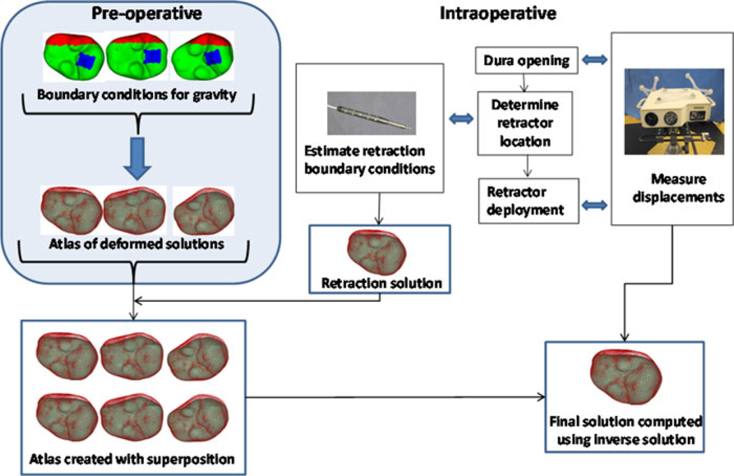
The basic technique for modeling retraction conditions will be similar to that of [20], where the mesh is split by duplicating the nodes at the tissue–retractor interface [21] and a classic forward-based solve of a finite-element model with modified mesh is performed. The generalized schematic of our approach to retraction integration is shown in Fig. 2. After building the displacement atlas preoperatively [3], intraoperatively, typically repeat laser range scans would be used to compensate for brain shift similar to previous atlas-based compensation work [3]. With the introduction of retraction, the steps would be altered. Prior to retractor deployment, a correction would be employed using the laser range scan. Once complete, a standard optically tracked localizer is used to determine the retractor deployment position. Based on the corrected brain and the location of the retractor in physical space, mesh splitting techniques from [20] are used and the side in contact with the retractor is prescribed fixed displacements along the direction normal to the retractor plane with sliding along the retractor permissible. The noncontact side has stress free boundary conditions and is free to move. Additional retractor solves are conducted to account for inaccuracies in digitization whereby the direction of the retraction is rotationally perturbed around the longitudinal axis of the plane of retraction (in a cone of vectors 5° around the central vector). Once complete and prior to appending these forward solutions to the original atlas (with a patient the original atlas would contain sag, swelling, and mannitol effects, but in phantom work herein, just sag), the original atlas must be modified to accommodate the additional nodes associated with mesh splitting. More specifically, in the original atlas, the created nodes are assigned displacements the same as their counterpart split node, i.e., both sides of split move together based on preoperative atlas. Once complete, the entire atlas containing original and appended retractor solutions can be created. By adding to the atlas in this manner, all laser range scans conducted postretraction can be fitted using our same framework but that fit will now be sensitive to the placement (or even eventual removal) of the retractor.
Fig. 2.
Schematic showing the overall workflow. Preoperatively, the deformation atlas is computed for gravity (three representative solutions shown in schematic— top left, atlas of deformed solutions). Intraoperatively, first sparse dataset is acquired after dura removal using a device such as a tracked LRS and just prior to retractor deployment. After the location where the retractor will be placed is determined by the surgeon, the location can be digitized and used to estimate the retractor location, and subsequently used to construct a tissue-retracted model with boundary conditions (often we introduce perturbations in those boundary conditions to account for errors in placement or slippage). Intraoperative retractor solutions are generated and appended to the atlas (note, the preoperative atlas is modified to accommodate extra degrees of freedom with the introduction of the retractor). Now any future LRS measurements can use this preconditioned retraction atlas to inversely solve for the model-based correction.
The inverse model for this modified system is solved in the following manner:
| (4) |
In the aforementioned equation, M̃ is the new atlas that has m gravity and nr retractor solutions appended. The value of m as described in (3) is 13 and the value of nr is 8 for this phantom work. Our complete atlas M̃ has a total of 21 solutions (m+nr). We should also note that M̃ has more surface nodes to consider than M, i.e., replicated nodes associated with the mesh splitting from retractor deployment are present at the brain surface (similarly, the volumetric solution atlas is more dense as a result of the entire domain being split along the retractor face). The least squared error is minimized subject to the constraints that the weighting coefficients for all gravity solutions sum to less than or equal to 1 as well as the weighting coefficients for all retraction solutions sum to less than or equal to 1. The homologous points from the serial laser range scans (usparse in (4)) are used as measurement points to inversely solve the model by minimization of least squared error.
B. Experimental Evaluation
The method described earlier was evaluated with simulation as well as phantom experiments that are described in the section below.
1) Simulations
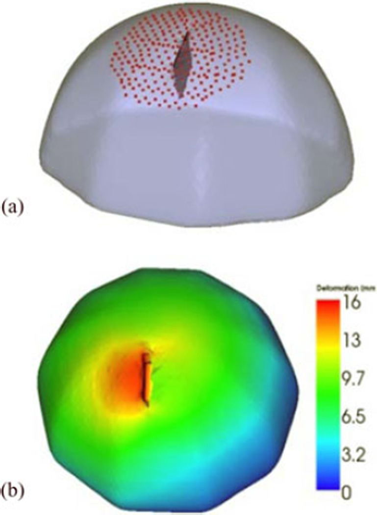
The performance of the model would depend on the accuracy of tracking the retractor location in the OR. The goal of the simulation experiments is to study the effect of error introduced into the system through tracking inaccuracies. A hemispherical volume with 20-cm diameter was created using VTK (Kitware Inc.) and then made into a tetrahedral mesh with 4.5-mm element size, resulting in ∼100 000 elements and ∼20 000 nodes. A reference solution was then created by deforming the mesh using gravity and retraction boundary conditions simultaneously with the linear elastic model, as shown in Fig. 3(b).
Fig. 3.
(a) Original undeformed mesh overlaid with the retractor plane and points on the surface used to run the inverse model. (b) Deformed solution created with simultaneous application of retraction and gravity boundary conditions color coded with deformation magnitude indicated on colorbar in mm units, used as reference to evaluate simulation results.
Based on intraoperative procedure information, a 1.5-cm retraction is simulated for the reference solution. A “preoperative atlas” that only contains gravity deformation solutions was then created using different orientations. Thirteen orientations and one fluid level were used to create the atlas consisting of 13 solutions, to which retraction solutions were appended. The number of solutions in the atlas was selected based on the results of a sensitivity study, discussed in Appendix A.
Upon completion of the atlas, a series of simulations to understand the effects of localization and rotational errors was conducted. More specifically, the location of the retractor plane was perturbed by translating or rotating it from its true location, and a forward model was solved. Nine different retractor plane perturbations were used—±0.5 cm, ±1 cm, ±15°, ±30° and the original plane (in this case nr is 9). The inverse model was driven by a set of points contained in a circular patch of radius 4 cm, centered at the retractor location on the boundary [see Fig. 3(a)]. The shift correction was computed at the surface points used to drive the atlas as well as subsurface points located 6 cm radially around the retractor location. In addition, the results were compared to an inverse solution using the preoperative atlas with gravity forces only.
2) Phantom Experiments
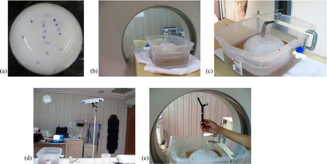
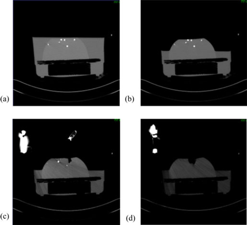
Polyvinyl alcohol cryogel (PVAc) material was molded into a hemisphere with diameter 17 cm. Surface and subsurface glass beads were embedded that could be tracked in a CT scanner [see Fig. 4(a)]. The bottom of the phantom was then fixed to a platform in a container and filled with water. The water level could be controlled with a spigot on the side [see Fig. 4(b)]. The top of the container was fixed with a retractor assembly, with which the PVAc phantom could be retracted to desired displacements [see Fig. 4(c)]. In addition to the acquisition of the CT scans, the location of the glass beads on the phantom was also localized using NDI Polaris Spectra [see Fig. 4(d)] and passively tracked tool tip [see Fig. 4(e)]. Four serial CT scans were acquired: (1) phantom completely submerged in water in an undeformed state, (2) after some water has been drained, (3) after placing the retractor, and (4) after performing the actual retraction, shown in Fig. 5(a)–(d). The setup was not moved during the scans, so all the images were co-localized in the same space. The undeformed state image was segmented from CT images of the setup and used to construct a finite-element mesh. The location of the retractor in the mesh was obtained from the third scan [see Fig. 5(c)] and used to split the nodes along that plane.
Fig. 4.
(a) PVAc phantom embedded with glass beads that can be tracked in a CT image. (b) Phantom fixed to the platform in the container, filled with water, being imaged in CT scanner. The water level is controlled with the spigot on the side. (c) Retraction assembly consists of a flat surface used as a retractor, which is fixed to the top of the container. (d) NDI Polaris Spectra camera used for tracking (e) passively tracked tool used to localize the location of glass beads on the phantom surface.
Fig. 5.
CT images acquired at different time points. (a) Undeformed image, (b) after water drainage, (c) after retractor is placed, and (d) after retractor is deployed.
A deformation atlas containing gravity solutions and superposed retractor solutions was constructed and markers on the surface were used to run the inverse model. The retraction modeling technique was evaluated with five phantom datasets, with tracking performed for three of the five cases.
III. Results
A. Simulations
The percent shift correction at the surface and subsurface points for the gravity atlas alone and the joint atlas containing gravity and retraction solutions is shown in Fig. 6. The mean shift correction is typically higher for most cases for both the surface and subsurface points using the superposed retraction atlas even in the presence of perturbed superposed retractor solutions. Since the percent correction for the points do not fall into a normal distribution, as determined by the Kolmogorov–Smirnov test (p < 0.05), the correction for each of the solutions that incorporate retraction was compared to the solution from gravity atlas alone using the Wilcoxon rank sum test. With a p < 0.05 significance, the shift correction results for the retraction solutions are different than the ones with gravity alone, except for the case where the retractor plane was moved −0.5 cm, where the null hypothesis could not be rejected.
Fig. 6.
Left graph shows the percent shift correction at the surface points for the atlas with gravity alone and with superposed retraction solutions with various displacements and orientation. The graph on right shows the data for subsurface points. The numbers on the x-axis show the various perturbations of the retractor plane as discussed in section 2.2, with “0” being the unperturbed location.
B. Phantom Experiments
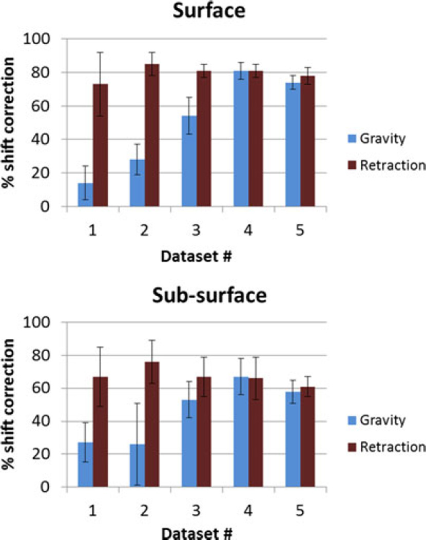
The atlas-based modeling technique with the gravity atlas alone and retraction superposed atlas was compared with the five phantom datasets. A number of markers and the measured displacements for each dataset are shown in Table I. For the five phantom datasets, it is reported at the surface points (which were used to constrain the least squared error solution) and subsurface points, using the gravity atlas and the superposed retraction atlas in Fig. 7.
TABLE I.
Number of Markers and Measured Displacements for the Five Phantom Datasets
| Surface | Sub-surface | ||||||
|---|---|---|---|---|---|---|---|
| # | # markers |
Average measured displacement (mm) |
Maximum measured displacement (mm) |
# markers |
Average measured displacement (mm) |
Maximum measured displacement (mm) |
Tracking available |
| 1 | 10 | 12.9±4.0 | 17.5 | 6 | 7.4±2.6 | 11.3 | No |
| 2 | 14 | 8.8±2.5 | 13.1 | 12 | 5.9±2.0 | 9.5 | No |
| 3 | 15 | 18.0±1.6 | 21.2 | 10 | 15.0±2.9 | 20.2 | Yes |
| 4 | 12 | 23.1±0.6 | 23.7 | 11 | 16.3±3.5 | 20.0 | Yes |
| 5 | 12 | 23.1±2.4 | 27.6 | 11 | 13.2±5.6 | 26.9 | Yes |
Fig. 7.
Percent shift correction for (top) surface and (bottom) subsurface points for the five phantom datasets in Table I using the gravity atlas and the superposed retraction atlas.
The percent shift correction data computed using the different atlases do not fall into a standardized normal distribution, as determined by the Kolmogorov–Smirnov test (p < 0.05). Using the Wilcoxon rank sum test, for the surface points, the superposed retraction atlas significantly (p < 0.05) improved the shift correction results for all datasets except for dataset #4. For the subsurface points, there is a significant (p < 0.05) increase in shift correction for the first three datasets, while there is no statistical change in the last two datasets. Optical tracking was also integrated into the phantom experiment and results (shown in Appendix B) were comparable to localization in the images.
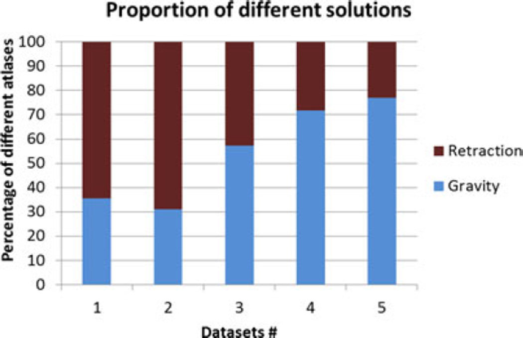
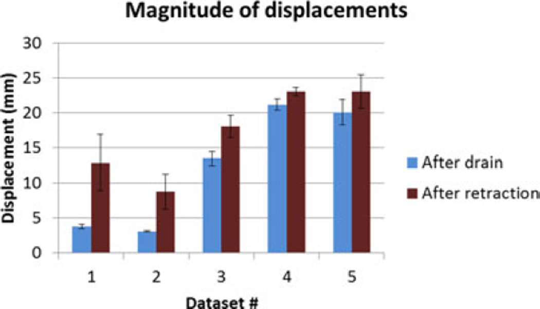
The superposed retraction atlas contained both gravity solutions alone as well as retraction solutions. Fig. 8 shows the proportion of the contribution of gravity and retraction solutions for the results reconstructed with the superposed retraction atlas. The measured displacement magnitudes at the embedded markers after fluid drainage and after retraction for the five datasets are shown in Fig. 9.
Fig. 8.
Percentage of contribution from different atlases to the solution reconstructed from the superposed retraction atlas.
Fig. 9.
Measured displacements at embedded surface bead markers after fluid drainage and after retraction for the five datasets.
It is important to note that the displacement after retraction is a cumulative magnitude of both drainage and retraction applied in succession. The deformation caused by gravity is relatively small for the first two datasets, and the contribution of retraction to the overall deformation is larger. This is reflected in the percentage of retraction solutions picked from the superposed atlas for the first two datasets in Fig. 8. The contribution by retraction is smaller in the last three datasets, and this trend is also reflected in the proportion of the weighting coefficients in the superposed atlas, as shown in Fig. 8.
IV. Discussion
The nonrigid deformation of brain tissue during surgery causes substantial error in the image guidance system. Usage of predictive computational models has shown promise because of cost efficiency and adaptability to wide range of data. The atlas-based method for brain shift correction was developed to account for uncertainties in the intraoperative environment that affected the characteristic of deformation but was difficult to determine to exact precision during surgery. The papers published in the past using the atlas-based method do not account for some intraoperative forces, such as resection and retraction [3], [16]. This paper presents a method to integrate retraction modeling in the atlas-based framework. While the relatively small atlas used in this phantom experiment takes little time to prepare, atlases for patient use are considerably larger. In [3], the atlases used for these patient cases were on the order of 700 solutions (i.e., m = 700) and would take approximately 13.1 ± 3.5 h. In the clinical context, the preoperative atlas comprises a variety of conditions such as gravity and mannitol and really needs to be computed a day prior to surgery. However, in recent sensitivity studies reported in [25], we have been able to reduce that computational load by 80% such that atlases take approximately 2.2 ± 0.6 h thus becoming a same-day-as-surgery possibility. With respect to retraction, without a priori knowledge of retractor location, a preoperative atlas that contains a range of retractor configurations would significantly increase computational cost. With the linear atlas superposition method proposed in this paper, intraoperative information about retractor location can be used with the precomputed atlas resulting in fast solution in the OR. The retractor localization, computation of limited retractor solutions using the linear elastic model and an inverse solution incorporating the linearly superposed atlas add 2–3 min of time cost to the overall workflow in the OR.
The simulation experiments demonstrated that the average percent shift correction obtained for surface and subsurface points is improved if retraction forces are accounted for in the model, even in the case of gross retractor alignment issues. This is interesting in that even if the retractor displacement is grossly incorrect, coefficient combinations are generated from the atlas technique to compensate for this gross tracking inaccuracy.
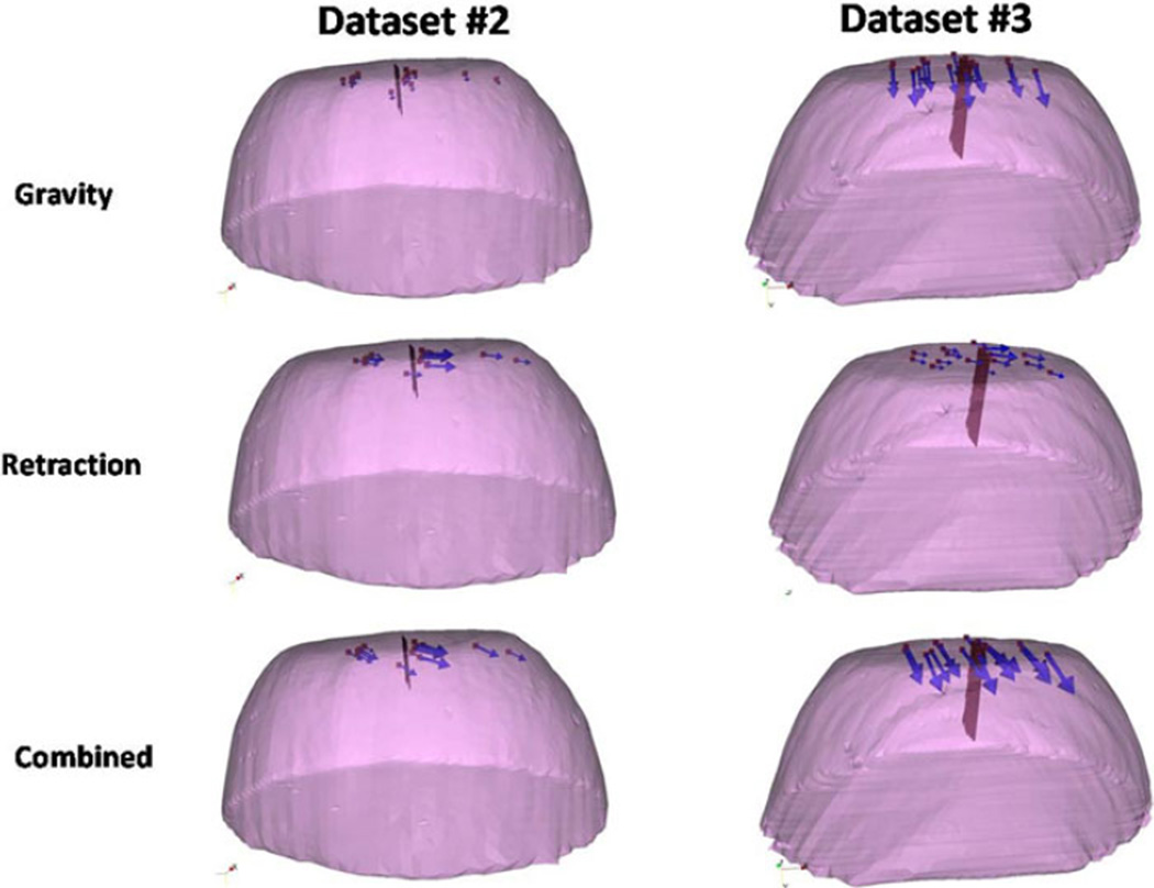
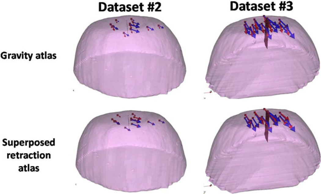
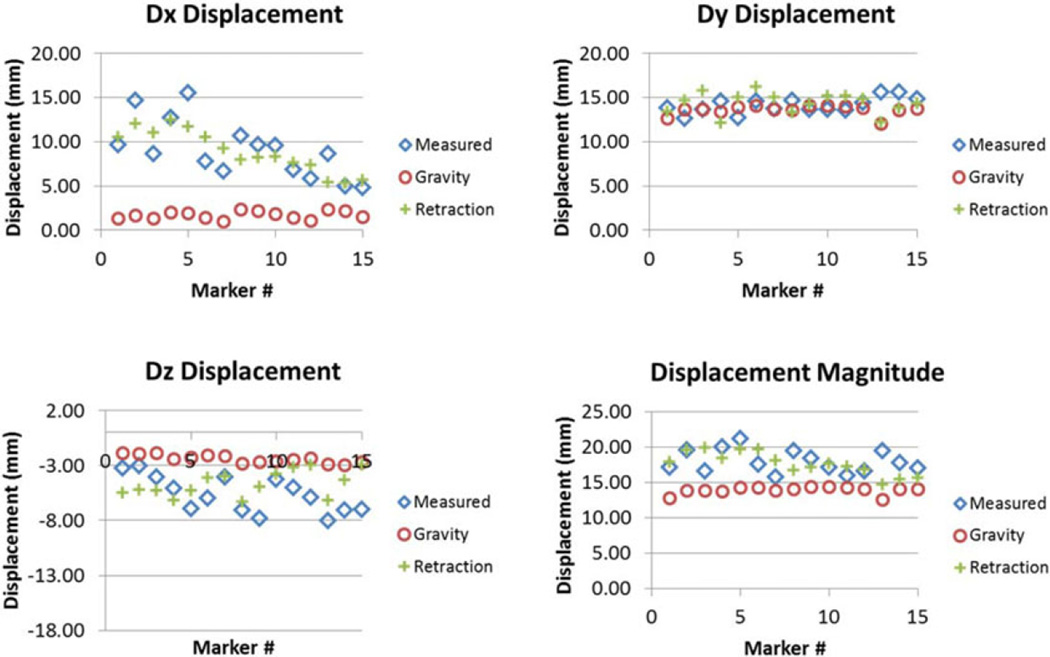
The results of the phantom experiments (see Fig. 7) showed a significant improvement for surface shift correction four out of five datasets. Through the use of the superposed retraction atlas, the first two datasets, the overall average shift correction improved by 57–59%, the third dataset showed an improvement by 27%, the fourth dataset showed no change, and the fifth dataset showed an improvement by 4%. The subsurface points mirrored this trend. The difference between varying degrees of improvement of shift correction in the five phantom datasets can be explained by the nature of displacements. As shown in Fig. 9, the magnitude of gravity displacement is smaller in the first two cases compared to the other cases. Fig. 10 shows the gravity, retraction, and combined gravity and retraction measurements for datasets #2 and #3. The gravity deformation is almost in the vertical direction whereas the retraction deformation is nearly horizontal in Fig. 10. Due to the relative magnitudes of the two forces in datasets #2 and #3, the combined deformation is weighted toward the horizontal direction for dataset #2 and the vertical direction for dataset #3. The gravity atlas is formed by tilting the phantom orientation around the vertical direction. Due to the more dominant gravitational component in dataset #3, the gravity atlas corrects for a larger extent in dataset #3 than dataset #2, which has a more dominant retraction component. This is demonstrated in Fig. 11. Fig. 11 illustrates the gravity atlas performing very poorly for dataset #2 because of the dominant retractor component and performing moderately better for dataset #3 because the gravity component is more comparable in magnitude to the retractor component. The superposed retractor atlas performs comparably in both the datasets. This same reason explains why dataset #5 only experienced a 4% shift correction improvement with the superposed retractor atlas, as seen in Fig. 9, the contribution of gravity deformation was much larger. Fig. 12 shows the displacement measurement and model predictions at individual surface markers for phantom dataset #3. When looking at the overall pattern of displacements, the gravity atlas produces more uniform deformations, which do not account for the local variations locally in a smaller subregion caused by retraction forces. The local variations are better captured by the atlas that contains retractor solutions.
Fig. 10.
Measurements for deformations caused by gravity, retraction and combined forces for datasets #2 and #3. The red surface is the retractor.
Fig. 11.
Measured vectors (blue) and the predicted vectors (red) using the gravity atlas and the superposed retractor atlas for datasets #2 and #3.
Fig. 12.
Comparison of the measured displacement with the prediction made using gravity atlas alone and retractor superposed gravity atlas in x (top left), y (top right), z (bottom left) directions and overall magnitude (bottom right) for phantom dataset #3.
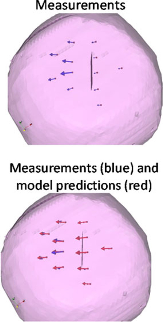
Finally, the results for phantom dataset #4 showed no change from the use of superposed retractor atlas versus the gravity atlas and merit some additional examination. Fig. 13 shows the deformation caused by retraction alone for dataset #4 and the correction for a forward model solve of retraction boundary conditions. It was observed that the markers on the retraction side for dataset #4 are located farther away from retractor as compared to the other datasets. The markers closest to the retractor for dataset #4 were 17 mm away from the retractor surface, and experienced a 3% improvement using the retractor atlas as compared to the gravity atlas. Whereas in the other cases, the markers in closest proximity to the retractor were less than 10 mm away from the retractor surface and experienced shift improvement from 12 to 75%. As we look at the field effect of an applied surface force from the retractor, we would anticipate that in the far-field away from local effects of deformation source, the loading associated with body forces (i.e., gravity-induced) would be more important. This would explain the diminished improvement contribution from retraction model in this case.
Fig. 13.
Deformation caused by retraction for dataset #4 and the model prediction using the forward solve of retractor boundary conditions.
There are several limitations in this study and sources of error in the proposed method. The goal of the study presented herein is to test the efficacy of the linear superposition of retractor computations with a precomputed deformation atlas built from models of common sources of brain shift. Due to the preliminary nature of the study, the testing was done in simulation and phantom data. These testing frameworks have intrinsic limitations and do not perfectly replicate the conditions seen in clinical data. The PVAc phantom experimental setup was unconstrained except being fixed at the base, whereas the behavior of the brain tissue in a constrained cranial space might be different. Another potential weakness that was not addressed in this study was that in a clinical setting, the size of the exposed craniotomy may be relatively small and the retractor may conceal features for homologous point analysis. In future work, this method of modeling retraction will be explored in clinical setting using the optical tracking setup.
The errors include the localization or tracking error. The location of the retractor in the phantom was determined by localizing the retractor plane and the mesh was split along the corresponding nodes in the undeformed state. However, when the retractor plane is localized, the fluid drainage has already occurred. While this can be accounted for with a “correction for sag,” there still may be some localization error. While the error was not significant in this simulation and phantom study, this effect could be mitigated to some extent by varying the retractor depths in the active solves as well as perturbations in location. Of course, this would have to be critically evaluated by its impact to workflow and model-update timing. An assumption was also made that the direction of retraction was normal to this recorded surface; however, the slipping or sliding of retractor would also result in some error. This was accounted for to some degree by building the retractor atlas through perturbation of the angle of retractor normal, as described previously. The effect of this error on the model prediction was small and this was supported by the simulation experiment results in Fig. 6. The method described in this paper for accounting for retraction showed improvement in simulation and phantom data and involves minimal additional computational effort of appending active solutions to the atlasbased framework previously described in [3].
V. Conclusion
In this paper, a method to integrate retraction modeling into the atlas-based framework to compensate for brain shift in the OR was presented and evaluated with simulation and phantom studies. The atlas-based framework of brain shift computation accounts for the uncertainties in the intraoperative environment by precomputing the deformations through different perturbations of boundary conditions and applied forces. This paper presents a novel yet simple way to integrate retraction into the atlas-based brain shift computation framework. The method is completely compatible with OR workflow and minimally cumbersome. While this paper does not incorporate all surgical variables, the goal of this paper was to study the feasibility of the integration of retraction modeling by active solving and linear superposition. The preliminary results presented here indicate this approach to be a promising avenue to pursue.
Acknowledgment
The authors would like to thank the CT technicians in the Department of Radiology at Vanderbilt University for their help in data collection. Most of the visualization algorithms were developed using Visualization Toolkit (http://www.vtk.org). Some segmentation and calculations were performed using Analyze AVW Version 9.0 and itk-SNAP Version 2.1.4.
This work was supported in part by the National Institutes of Health (NIH)-National Institute for Neurological Disorders and Stroke under Grant R01 NS049251.
Appendix A
The atlas building is the most time consuming and critical step to our deformation compensation approach. In past work, we have varied the resolution and extent of those atlases [3]. As the work now moves toward validation and intraoperative use, it is important to place the construction of the atlas within the context of workflow. More specifically, as we translate the study into an intraoperative pipeline coupled with the uncertainty and error with intraoperative data collection, it is important to revisit the atlas process.
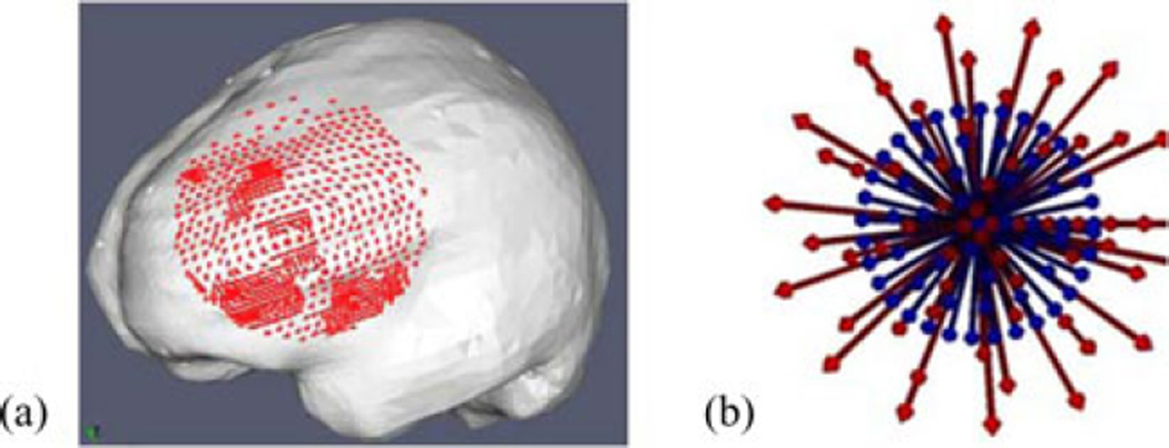
A sensitivity study using simulations was conducted to evaluate the effect of atlas size on accuracy of the inverse model. Since the largest contribution to the atlas size came from the number of head orientations, this will be the main parameter studied in the simulation experiment. In this experiment, an FEMc mesh was generated from patient-specific MR data. In this particular case, retraction was not performed. The tumor structure, though not shown in Fig. 14, was also segmented and modeled as a second material in the mesh.
Fig. 14.
(a) Mesh used for the simulation experiments, the displacement solutions of the forward runs at the craniotomy nodes (red) used to simulate sparse data, (b) Blue shows the head orientations in that atlas. Red arrows show the head orientation of the ground truth solutions.
Forward model runs with varying head orientations and other forcing conditions were generated. Acquisition of sparse intra-operative displacement data was simulated by selecting the displacement solutions for the nodes in the craniotomy region, close to the tumor [see Fig. 14 (a)]. Fig. 14 (b) shows the experiment conducted to study the effect of spatial extent, the blue arrows (corresponds to the direction of the gravity vector) show the head orientation of each solution in the atlas, the extent of the cone is 20°. The red arrows show the head orientations corresponding to ground truth solutions (i.e., ground truth solutions were not part of atlas and will be the results we would like to reconstruct from the atlas of solutions approach), consist of concentric cones ranging from 2.5° to 32.5° to the center, in the increments of 5°. The inverse reconstruction was executed with special care never to include the “ground truth” solution being sought.
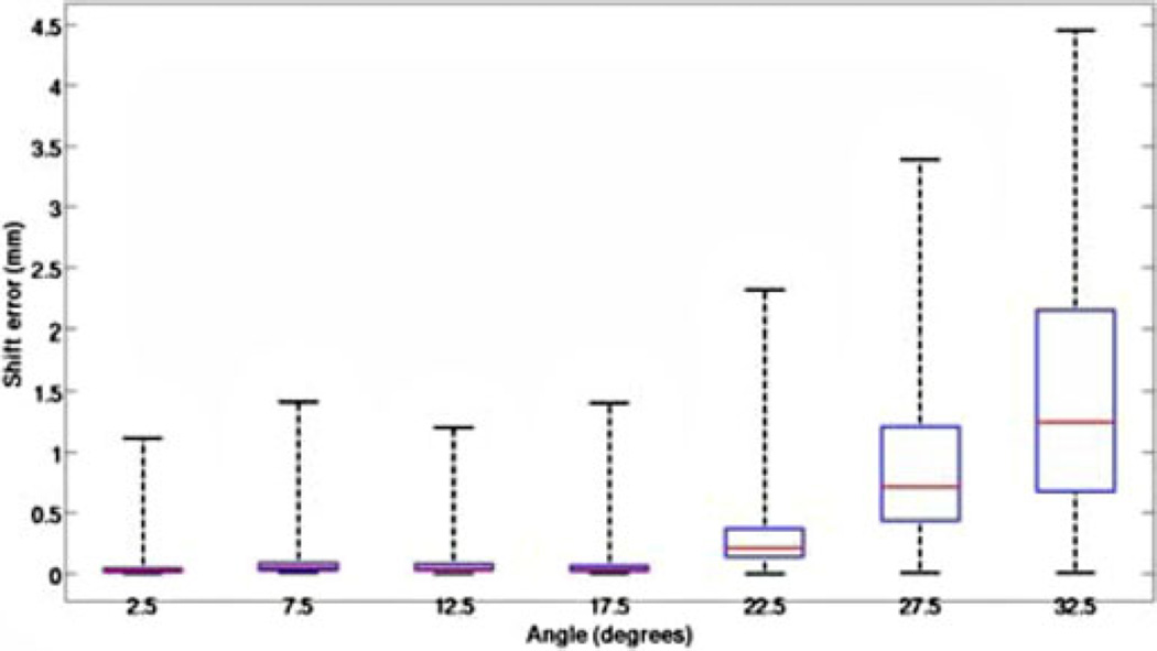
Fig. 15 reports the shift correction error for reconstructing ground truth solutions varying from 2.5° (center of cone in Fig. 14(b) to 32.5° (solutions outside the atlas 20° cone). The results for error between the location of model-predicted and ground truth points was averaged for each head orientation that was at the same angle from the center of the cone. Fig. 15 shows the error is minimal when the actual head orientation is contained within the cone of head orientations used to construct the deformation atlas. As expected, we do see a systematic increase in error as the ground truth is not contained in the atlas.
Fig. 15.
Box and whisker plot for error between model prediction and measurements for the simulation experiment. The x-axis represents the angle from the center of cone of atlas of head orientations and head orientation used to generate the ground truth. The red line represents the median, the box represents the twenty fifth and seventy fifth percentiles and the whiskers represent the extent of data.
Give the aforementioned result, we can conclude that reasonable predictions are consistently possible if our atlas contains the shift orientation. This is readily accomplished in current workflow as we do have a very preoperative planning phase with the surgeon where they approximate head orientation and craniotomy orientation. However, another critical aspect to consider in light of preoperative computing is the requirements of the spatial resolution of our atlas. In another simulation experiment, the effect of spatial resolution was tested where the number of head orientations in the atlas varied from 5, 14, 21, 30, 43, and 59. The results showed that the error was modestly larger for the atlas with the coarser resolution and then quickly became asymptotic for both surface and subsurface nodes. Sampling the space more finely did not significantly improve the shift correction. The findings indicated that the error became asymptotic with a sampling of orientation containing approximately 20 distributed solution samples.
Appendix B
The previous results presented were computed exclusively using the CT images for localization data. In the experiment, in addition to the CT data, the location of the embedded surface markers was also recorded using optical tracking which is typically available during surgery. In addition, the retractor plane was created by marking four edges of the retractor plane, creating a plane contained within the points and splitting the mesh along the plane. The entire process including the localization and mesh splitting takes minimal time. The tracked data were registered to the CT images using fixed reference fiducials. Table II below shows the fiducial registration error (FRE) and the target registration error (TRE) for the markers tracked.
TABLE II.
Fre and Tre Between Image and Physical Space
| Dataset # | # fiducial markers |
FRE (mm) | # target markers |
TRE (mm) |
|---|---|---|---|---|
| 3 | 6 | 0.6±0.2 | 15 | 1.8±0.7 |
| 4 | 5 | 0.7±0.5 | 12 | 1.9±1.3 |
| 5 | 8 | 0.7±1.7 | 12 | 1.9±1.0 |
These optical tracking data were only available for the phantom datasets #3–5. The errors listed in Table I are a composite of both the localization error of the markers in the image and the registration error whereas Table II also incorporates optical tracking error.
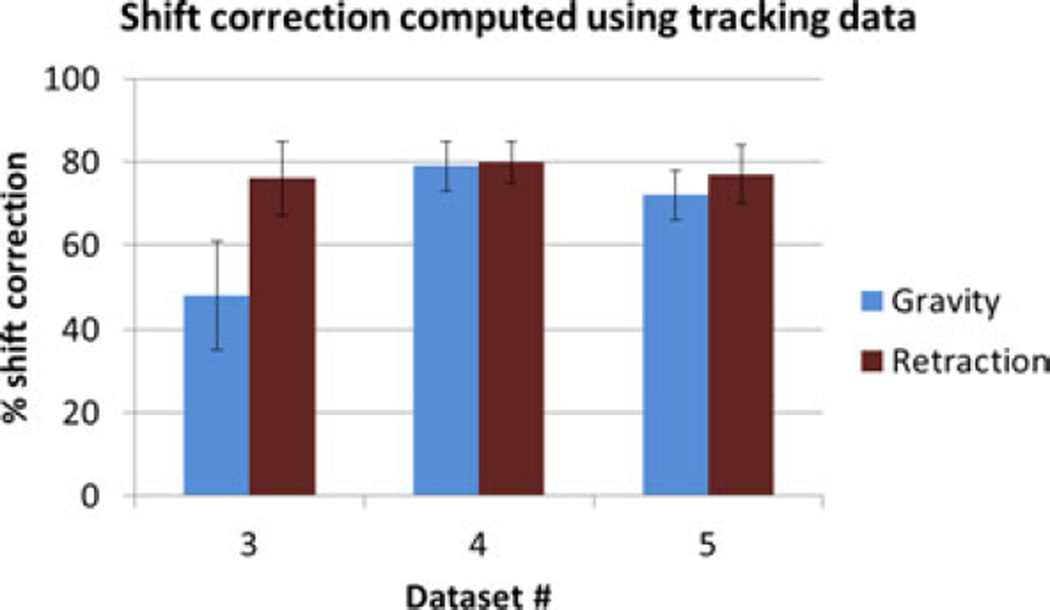
The shift correction results obtained using the optical tracking data are shown in Fig. 16. Comparing these results to the shift correction results obtained using data from the images for phantom datasets #3–5 shown in Fig. 7, the values are comparable and follow a similar trend emphasizing that similar results in realistic surgical scenario are likely.
Fig. 16.
Shift correction using tracking data for phantom datasets #3–5.
Contributor Information
Ishita Chen, Email: ishita.chen@vanderbilt.edu, Department of Biomedical Engineering, Vanderbilt University, Nashville, TN 37235 USA.
Rowena E. Ong, Email: rowena.ong@vanderbilt.edu, Department of Biomedical Engineering, Vanderbilt University, Nashville, TN 37235 USA.
Amber L. Simpson, Email: simpson@vanderbilt.edu, Department of Biomedical Engineering, Vanderbilt University, Nashville, TN 37235 USA.
Kay Sun, Email: kay.sun@vanderbilt.edu, Department of Biomedical Engineering, Vanderbilt University, Nashville, TN 37235 USA.
Reid C. Thompson, Email: reid.c.thompson@vanderbilt.edu, Department of Neurological Surgery, Vanderbilt University, Nashville, TN 37232 USA.
Michael I. Miga, Email: michael.i.miga@vanderbilt.edu, Department of Biomedical Engineering, Vanderbilt University, Nashville, TN 37235 USA.
References
- 1.Roberts DW, Hartov A, Kennedy FE, Miga MI, Paulsen KD. Intraoperative brain shift and deformation: A quantitative analysis of cortical displacement in 28 cases. Neurosurgery. 1998 Oct;43:749–758. doi: 10.1097/00006123-199810000-00010. [DOI] [PubMed] [Google Scholar]
- 2.Nimsky C, Ganslandt O, Cerny S, Hastreiter P, Greiner G, Fahlbusch R. Quantification of, visualization of, and compensation for brain shift using intraoperative magnetic resonance imaging. Neurosurgery. 2000 Nov;47:1070–1079. doi: 10.1097/00006123-200011000-00008. [DOI] [PubMed] [Google Scholar]
- 3.Chen I, Coffey AM, Ding S, Dumpuri P, Dawant BM, Thompson RC, Miga MI. Intraoperative brain shift compensation: accounting for dural septa. IEEE Trans. Biomed. Eng. 2011 Mar;58(3):499–508. doi: 10.1109/TBME.2010.2093896. [DOI] [PMC free article] [PubMed] [Google Scholar]
- 4.Butler WE, Piaggio CM, Constantinou C, Nikalson L, Gonzales RG, Cosgrove GR, Zervas NT. A mobile computed tomographic scanner with intraoperative and intensive care unit applications. Neurosurgery. 1998;88:1304–1310. doi: 10.1097/00006123-199806000-00064. [DOI] [PubMed] [Google Scholar]
- 5.Letteboer MMJ, Willems PWA, Viergever MA, Niessen WJ. Brain shift estimation in image-guided neurosurgery using 3-D ultrasound. IEEE Trans. Biomed. Eng. 2005 Feb;52(2):268–276. doi: 10.1109/TBME.2004.840186. [DOI] [PubMed] [Google Scholar]
- 6.Gobbi D, Comeau R, Peters T. Medical Image Computing and Computer Assisted Intervention (Lecture Notes in Computer Science) Vol. 1679. Berlin, Germany: Springer; 1999. Ultrasound probe tracking for real-time ultrasound/MRI overlay and visualization of brain shift,” in; pp. 920–927. [Google Scholar]
- 7.Gobbi D, Comeau R, Peters T. Medical Image Computing and Computer Assisted Intervention: Lecture Notes in Computer Science. Vol. 1935. Berlin, Germany: Springer; 2000. Ultrasound/mri overlay with image warping for neurosurgery,” in; pp. 29–53. [Google Scholar]
- 8.Clatz O, Delingette H, Talos IF, Golby AJ, Kikinis R, Jolesz F, Ayache N, Warfield S. Robust non-rigid registration to capture brain shift from intraoperative MRI. IEEE Trans. Med. Imag. 2006 Nov;24(11):1417–1427. doi: 10.1109/TMI.2005.856734. [DOI] [PMC free article] [PubMed] [Google Scholar]
- 9.Wittek A, Miller K, Kikinis R, Warfield SK. Patient-specific model of brain deformation: Application to medical image registration. J. Biomech. 2007;40:919–929. doi: 10.1016/j.jbiomech.2006.02.021. [DOI] [PubMed] [Google Scholar]
- 10.Skrinjar O, Nabavi A, Duncan J. Model-driven brain shift compensation. Med. Image. Anal. 2002 Dec;6:361–373. doi: 10.1016/s1361-8415(02)00062-2. [DOI] [PubMed] [Google Scholar]
- 11.Sun H, Roberts DW, Farid H, Wu Z, Hartov A, Paulsen KD. Cortical surface tracking using a stereoscopic operating microscope. Neurosurgery. 2005;56:86–97. doi: 10.1227/01.neu.0000146263.98583.cc. [DOI] [PubMed] [Google Scholar]
- 12.Audette MA, Siddiqi K, Ferrie FP, Peters TM. An integrated range-sensing, segmentation and registration framework for the characterization of intra-surgical brain deformations in image-guided surgery. Comput. Vis. Image. Understanding. 2003 Feb-Mar;89:226–251. [Google Scholar]
- 13.Sinha TK, Dawant BM, Duay V, Cash DM, Weil RJ, Miga MI. A method to track cortical surface deformations using a laser range scanner. IEEE Trans. Med. Imag. 2005 Jun;24(6):767–781. doi: 10.1109/TMI.2005.848373. [DOI] [PMC free article] [PubMed] [Google Scholar]
- 14.Sinha TK, Miga MI, Cash DM, Weil RJ. Intraoperative cortical surface characterization using laser range scanning: Preliminary results. Neurosurgery. 2006;59:368–376. doi: 10.1227/01.NEU.0000222665.40301.D2. [DOI] [PMC free article] [PubMed] [Google Scholar]
- 15.Dumpuri P, Thompson RC, Dawant BM, Cao A, Miga MI. An atlas-based method to compensate for brain shift: Preliminary results. Med. Image. Anal. 2006;11:128–145. doi: 10.1016/j.media.2006.11.002. [DOI] [PMC free article] [PubMed] [Google Scholar]
- 16.Dumpuri P, Thompson RC, Cao A, Ding S, Garg I, Dawant BM, Miga MI. A fast efficient method to compensate for brain shift for tumor resection therapies measured between preoperative and postoperative tomograms. IEEE Trans. Biomed. Eng. 2010 Jun;57(6):1285–1296. doi: 10.1109/TBME.2009.2039643. [DOI] [PMC free article] [PubMed] [Google Scholar]
- 17.Biot MA. General theory of three-dimensional consolidation. J. Appl. Phys. 1941;12:155–164. [Google Scholar]
- 18.Russell AJ, Bringas JR. A review of brain retraction and recommendations for minimizing intraoperative brain injury. Neurosurgery. 1993 Dec;33:1052–1064. doi: 10.1227/00006123-199312000-00014. [DOI] [PubMed] [Google Scholar]
- 19.Xu W, Mellergard P, Ungerstedt U, Nordstrom CH. Local changes in cerebral energy metabolism due to brain retraction during routine neurosurgical procedures. Acta Neurochir (Wien) 2002 Jul;144:679–83. doi: 10.1007/s00701-002-0946-1. [DOI] [PubMed] [Google Scholar]
- 20.Platenik LA, Miga MI, Roberts DW, Lunn KE, Kennedy FE, Hartov A, Paulsen KD. In vivo quantification of retraction deformation modeling for updated image-guidance during neurosurgery. IEEE Trans. Biomed. Eng. 2002 Aug;49(8):823–835. doi: 10.1109/TBME.2002.800760. [DOI] [PubMed] [Google Scholar]
- 21.Miga MI, Roberts DW, Kennedy FE, Platenik LA, Hartov A, Lunn KE, Paulsen KD. Modeling of retraction and resection for intraoperative updating of images. Neurosurgery. 2001 Jul;49:75–84. doi: 10.1097/00006123-200107000-00012. discussion 84–85. [DOI] [PubMed] [Google Scholar]
- 22.Sun H, Kennedy FE, Karlson EJ, Hartov A, Roberts DW, Paulsen KD. Modeling of brain tissue retraction using intraoperative data. Med. Image. Comput. Comput.-Assisted Intervention. 2004;3217:225–233. [Google Scholar]
- 23.Wittek A, Hawkins T, Miller K. On the unimportance of constitutive models in computing brain deformation for image-guided surgery. Biomech. Model Mechanobiol. 2009 Feb;8:77–84. doi: 10.1007/s10237-008-0118-1. [DOI] [PMC free article] [PubMed] [Google Scholar]
- 24.Gill PE, Murray W, Wright MH. Practical Optimization. London, U.K: Academic; 1981. [Google Scholar]
- 25.Chen I, Simpson AL, Sun K, Thompson RC, Miga MI. Sensitivity analysis and automation for intraoperative implementation of the atlas-based method for brain shift correction. Proc. SPIE Med. Imag.: Image-Guided Proc. Robot. Interventions, Model. 2013;8671:86710T1–86710T12. [Google Scholar]


