Abstract
Magnetic resonance imaging (MRI) is a widely used nonionizing and noninvasive diagnostic instrument to produce detailed images of the human body. The radio-frequency (RF) coil is an essential part of MRI hardware as an RF front-end. RF coils transmit RF energy to the subject and receive the returning MR signal. This paper presents an MRI-compatible hardware design of the new automatic frequency tuning and impedance matching system. The system automatically corrects the detuned and mismatched condition that occurs due to loading effects caused by the variable subjects (i.e., different human heads or torsos). An eight-channel RF transceiver head coil with the automatic system has been fabricated and tested at 7 Tesla (T) MRI system. The automatic frequency tuning and impedance matching system uses digitally controlled capacitor arrays with real-time feedback control capability. The hardware design is not only compatible with current MRI scanners in all aspects but also it operates the tuning and matching function rapidly and accurately. The experimental results show that the automatic function increases return losses from 8.4 dB to 23.7 dB (maximum difference) and from 12.7 dB to 19.6 dB (minimum difference) among eight channels within 550 ms. The reflected RF power decrease from 23.1 % to 1.5 % (maximum difference) and from 5.3 % to 1.1 % (minimum difference). Therefore, these results improve signal-to-noise ratio (SNR) in MR images with phantoms.
Index Terms: Automatic impedance matching and frequency tuning network, Magnetic Resonance Imaging (MRI), RF power detection, RF coil
I. Introduction
High magnetic field MRI systems have better signal-to-noise ratios (SNR), spatial resolution, and contrast in MR images [1]-[3]. The traditional clinical 1.5 T magnet is being replaced by 3 T and research magnets of 7 T and 9.4 T are being used for animals and the human images [1],[3]. Higher magnetic field strengths require higher operating frequencies defined by the Larmor frequency formula given by (1)
| (1) |
where fLarmor is the Larmor frequency (MHz), B0 is a static magnetic field strength (T), and γ is the gyromagnetic ratio (MHz/T) and is 42.58 for protons, 1H, which are used in MRI.
Despite the above-mentioned many advantages, the use of high frequencies complicates the design and implementation of the MRI hardware [1],[3]-[6]. An RF coil creates the RF transmission magnetic field (B1) to excite protons and receives the nuclear magnetic resonance (NMR) signal as shown in Fig. 1. The RF coils are tuned to the Larmor frequency to create resonant B1 fields and are matched to the source impedance of 50 Ω to maximize RF power transfer efficiency [7]. The variable subjects (e.g., different human heads or torsos) load on the RF coil and alter the both tuning and matching conditions. Therefore the power transmission efficiency and the SNR decrease. In current clinical systems (1.5 T or 3 T), RF coils operate at conditions of fixed tuning and fixed matching that cannot be adjusted by any existing practical means. This results in suboptimum RF coil performance. At current ultrahigh field (7 T and beyond) research, RF coil should be manually tuned and matched before every MR scanning because the loading-induced resonant frequency shift and quality (Q) factor decrease become severe when a subject is placed on the RF coil.
Fig. 1.
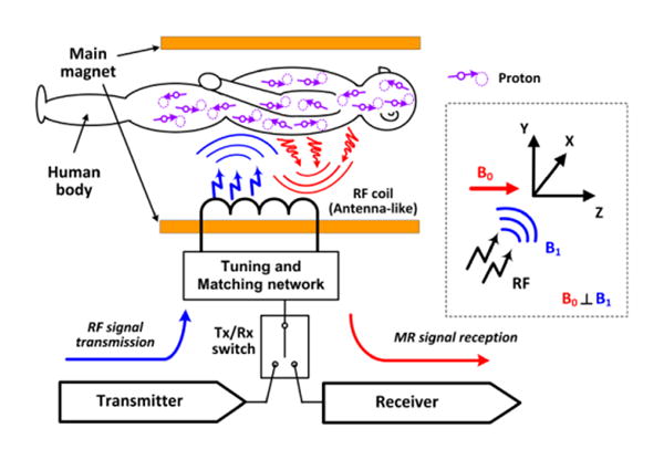
A system structure of MRI hardware and the three dimensional coordination with the direction of the static magnetic field (B0) and the RF magnetic field (B1) for MRI system (inside dotted box).
An RF coil design has moved from the birdcage coils to the pioneering transverse electromagnetic (TEM) coils at ultrahigh fields because the TEM coil structure can satisfy high frequency operations and multi-channel applications [3],[7]. There, however, is an inevitable loading effect due to high-Q property of the TEM coils that is no different from most RF coil types. The resonant frequency of the TEM coil shifts down about 1 % to 3 % resulting in 5 % to 20 % power reflection when a human head is placed on the coil at 7 T [8]. These variations are out of range of the RF coil's acceptable performance because not only low RF power transmission cannot create NMR signals enough to produce high quality MR images but also such power reflection can cause a safety problem and damage RF components. The current manual readjustment method to correct variations of loaded coils is a time-consuming process as the modern MRI trends toward multi-channel technology and is impractical in clinical applications.
In this study, the design of an automatically tuned and matched head coil for both the transmission and reception (transceiver) of RF signals has been investigated. The following sections show that a fully automatic tuning and matching RF coil offers the feasibility of overcoming limitations of the current manual method without adverse impact on MR images.
II. Preview of RF System and Loading Effect in MRI
A. RF system in MRI
RF hardware of MRI is similar to a general wireless communication system. An RF coil transmits RF pulses into the human body with the high power capability (∼ 60 dBm) and receives RF signals (∼ -20 dBm) generated by the proton's nuclear magnetic resonance. Differences are that it works under strong magnetic fields, and the transmitted and received RF signals present RF magnetic near-field (B1) that must be perpendicular to the static magnetic field (B0) as illustrated in Fig. 1.
B. TEM RF coils
An RF coil creates a time-varying RF magnetic near-field (B1) at the Larmor frequency in specific regions of the human body as shown in Fig. 2(a) and (b). The performance of RF coils determines the MR image quality as an RF front-end. Thus, various types of RF coils have been proposed including loops, birdcage coils and TEM coils. The TEM coil elements are driven independently and has an individual current's returning path. So, it offers easy manipulation for the multi-channel technology and high frequency operation [7],[9]. As shown in Fig. 2(c), a single TEM element consists of a microstrip transmission line (MTL) and its finite shield as RF ground. This structure is typically terminated by capacitors: two variable capacitors, the matching capacitor (Cm) and tuning capacitor (Ct), at RF input side; a fixed value capacitor (Cf) on the other end to form a capacitively tuned, matched, and foreshortened half-wave resonator. When Ct and Cm are well tuned to the Larmor frequency and matched to the source impedance of 50 Ω, the RF coil efficiently delivers RF power to the coil's resonator and maximizes the transmitted RF (B1+) magnetic near-field causing high NMR signals. The capacitively terminated TEM structure should resonate at the Larmor frequency by adjusting the tuning capacitor, and the RF coil element is matched to the source impedance of 50 Ω by adjusting the matching capacitor as shown in Fig. 3. Although a tuning capacitor and matching capacitor separately have dominant roles, both steps affect each other and the final values are decided by back and forth operation in practical.
Fig. 2.
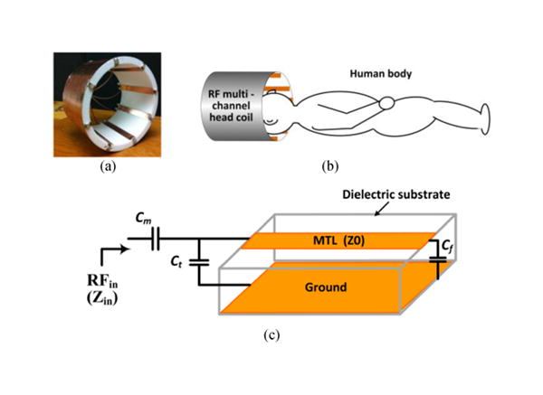
TEM RF coil: (a) an example of RF transceiver multi-channel head coil, (b) loading condition of a human head, and (c) a TEM RF coil element structure.
Fig. 3.
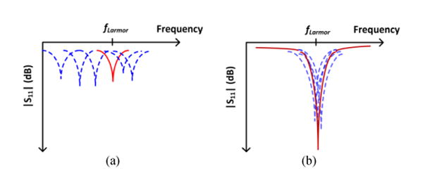
Concept of frequency tuning with a variable tuning capacitor (a) and impedance matching with a variable matching capacitor (b).
C. Loading (body) effect
The loading effects caused by a human body vary according to subject's shape, size, composition, and distance between the subject and the coil element, thus it is hard to predict the impact of loading effects on RF coil's performance [10]-[12]. Fig. 4(a) shows the loading effects resulting in a variation of the resonance frequency and the Q from the preset condition depending on different loading conditions. The resonance frequencies shift down causing high RF power loss at the Larmor frequency (fLarmor), and the Q is lowered causing high noise level. The reflected RF power level becomes significantly high unless tuning and matching readjustment is done. Fig. 4(b) and (c) show the comparison of the transmitted RF magnetic fields inside the phantom between the detuned/mismatched condition caused by phantom loading (Fig. 4(b)) and the tuned/matched condition (Fig. 4(c)) after the readjustment. Since the MR image quality is directly related to the strength of RF near-field (H), higher values results in higher signal intensity and therefore higher SNR [3],[5].
Fig. 4.
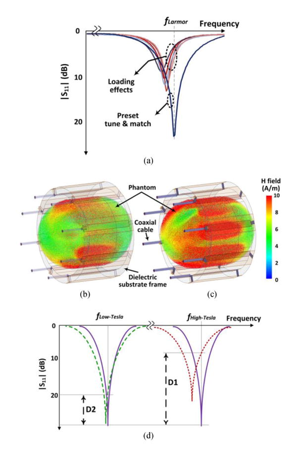
Loading effects: (a) return losses according to different human bodies compared to the preset condition, the simulation results of the multi-channel transmitted magnetic field, B1, inside a phantom between detuned/mismatched (b) and tuned/matched (c) RF coil, and (d) frequency shifts by the same loading condition at the low field (D2) and high field (D1).
The loading effect becomes a serious problem at ultrahigh fields because even the same loading condition makes a significant change as shown in Fig. 4(d). For example, when approximately 3-9 MHz (1-3 %) of the resonance frequency shift down from the initially tuned and matched preset condition at 7 T, it causes over 10 dB difference (D1) in the reflection coefficient (S11) and 50-200 W RF power loss in case of the RF input power of 1kW. However, in case of a low frequency region (e.g., 1.5 T), the insignificant variation (D2) occurs because the loading-induced variation of electrical properties is relatively small compared to the intrinsic values of the RF coil to resonate at the low frequency region.
RF coils cannot efficiently create high B1+ magnetic field without readjustments to tune and match after a patient is loaded at ultrahigh fields, and this is a critical obstacle in the modern MRI systems. Consequently, the current manual method should be replaced with the automatic tuning and matching technology. Some papers about an automatic tuning and matching system in MRI have been published but all approaches of them are only related to receive side, not transmit or transceiver [13]-[18].
III. Hardware Design of Automatic System
A. Overview of the system
The automatic tuned and matched RF coil element consists of an RF coupler, a RF power monitor, electrically switched capacitor arrays (Cp1: matching capacitor and Cp2: tuning capacitor) with PIN diodes, a main controller, and a TEM RF resonator as shown in Fig. 5(a). In the overall operation, there are two steps synchronized with a trigger signal (str) from an MRI console: the first step is the automatic tune and match procedure with the moderate RF power level (less than 0.1 W), and the second step is the normal MRI scanner operation with high power RF signal (up to 1 kW). In the first step, the output of the RF power monitor represents the reflected power level caused by impedance mismatch at the input of the TEM RF coil element. With this information, the main control and decision block determines the optimum frequency and impedance condition. The capacitor arrays are built with the microstrip Π matching network as shown in Fig. 5(b) to adjust the reactance values by switching PIN diodes. The capacitor array has four branches consisting of PIN diodes and capacitors in both the tuning and matching side. Therefore, a total of 256 different impedance states can be generated. Fig. 5(c) shows the input impedance (Zin) range made by the capacitor arrays on the Smith chart. The triangle (red) at the center is the preset matched condition at the Larmor frequency. Other dots indicate the impedances as the results of digitally switched PIN diodes from the loading effect, the square (blue). The range of impedances on the Smith chart is determined by capacitor values at each branch, and there is a tradeoff between the range and resolution of impedances produced. Since the bottom part of the head coil has more severe loading effect than the top part, capacitor values are selected through a test bench. The reflected RF power is measured to monitor the load conditions during the adjustment of capacitances, and eventually the main controller finds the minimum reflected power condition as an optimal impedance match at the Larmor frequency.
Fig. 5.
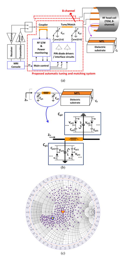
(a) The system diagram, (b) a single RF coil element with Pi matching network of digitally controlled capacitor array by PIN diodes switching, and (c) the impedance range of the capacitor array in (b) on the Smith chart.
B. Reflected RF power monitoring
RF power monitoring is an indispensable part of a real-time tuning and matching feedback system. A commercialized RF power detector (LTC5507, Linear technology, Milpitas, CA, USA) based on the Schottky diode's peak detection is used to get the stable RF power measurement and to satisfy the requirements of this study such as input dynamic range, power supply option, effects of the strong magnetic field, etc. The high accuracy of the power monitoring circuit cannot be obtained without a high directivity coupler [19]. The custom-built RF coupler has the coupling factor of 27 dB, the isolation of 45 dB, and the directivity of 18 dB. When capacitances of capacitor arrays vary with PIN diode switching, the RF power reflection through the coupler is connected to the input of the power detector circuit and then the DC voltage output that is proportional to the reflected RF power is generated.
C. Main controller and PIN diode driver
An automatic control algorithm was implemented into the FPGA (Field Programmable Gate Array) core (Cyclone 4 series, Altera) using Verilog HDL (Hardware Description Language). The 12-bit ADC (ADC128S, National Semiconductor, Lewisville, TX) converts the sampled RF reflection power into 12 bit digital signals for the computation in the FPGA core. The automatic function algorithm has been run with the real-time output of the RF power monitoring circuit, and it switches PIN diodes through the output of the PIN diode drivers. The PIN diode switching control signals are generated by the FPGA, and the reflected RF power signals are sampled simultaneously as shown in the time diagram in Fig. 6. This algorithm follows timing constraint of the MRI system (Siemens Magnetom 7 T) that is used for this study. The minimum interval between RF pulse packets is 2 ms, and multi-sampler samples the reflected power level generated by the RF power measurement circuit after PIN diode switching. The PIN diodes are switched after the RF pulse pocket to eliminate the influence of high power RF signals. The state toggle signal in Fig. 6 indicates the duration of tuning or matching control based on the tuning and matching processes in Fig. 3, and several iterations may be used to increase the accuracy of the performance of the system. To switch PIN diodes (MA4P7470F, M/A-COM technology, Lowell, MA, USA), a level shifter and an amplifier are required to make dual high voltages and high current driving capability. The level shifter generates moderate dual output voltages and the high power amplifier (OPA552, Texas Instruments, Dallas, TX) amplifies it to completely turn on or off PIN diodes against high power RF signals. In case of the forward bias, each PIN diode needs at least 20 mA to be turned on. In case of the reverse bias condition to completely turn off the PIN diode, the reverse voltage should keep the proper voltage level (less than -25 V) to prevent the RF leakages through PIN diodes [20].
Fig. 6.
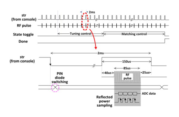
Time diagram of the automatic tuning and matching function.
D. 8-channel RF transceiver head coil for 7 T
The 8-channel RF head coil design with the automatic tuning and matching system is shown in Fig. 7. The TEM RF coil part has been built with the copper trace on the low loss Teflon substrate (height of 1.9 cm and length of 14 cm) and, eight elements attached to a cylindrical shell with 25.4 cm in inner diameter. The automatic control box driving the eight channels is installed next to the TEM RF resonator part. Capacitor arrays in a single element have two main trimmer capacitors (NMAJ40HV, Voltronics, Salisbury, MD, USA) to build the microstrip Π matching network. Four capacitor branches to adjust capacitances from a basis of the main trimmer capacitor value were implemented at the tuning and matching side, respectively. Each branch consists of one PIN diode and one capacitor with small capacitance (1 pF to 3.5 pF) depending on the position of a coil element. The combination of capacitances controlled by switching PIN diodes usually covers the range of 1 pF to 8 pF to correct the loading effect depending on the results of the test bench experiment. Each coil channel was initially tuned to 297.2 MHz for 7 T and matched to 50 Ω through a coaxial cable with the default PIN diode switching condition. The RF switch in the RF detector block changes the direction of the coupled RF power signal path toward the ground after the completion of the automatic function to protect low power circuits during high RF power operation. For the fully automated stand-alone system operation, the RF un-blank signal (str) from the MR console is used to activate or deactivate the automatic tuning and matching function.
Fig. 7.
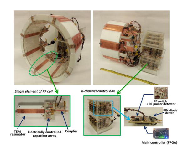
8-channel RF transceiver head coil with the automatic tuning and matching system.
IV. Test Bench and Results
A. Overview of the test bench setup
Before installing a new device in the MRI system, a test bench is necessary to verify the performance with high RF power, the radiation effects by the RF coil resonators, and system interfaces because measuring electrical signals inside an MRI room is difficult, and there are many restrictions to use an MRI machine. Therefore, the same condition except for a strong magnetic field surrounding is required on the test bench. The use of RF un-blank gating signal (str) to active or deactivate RF pulse is the only way to communicate with a console of an MRI scanner, and it is required to build a stand-along automatic running device synchronized with an MRI system. In the test bench setup, a replica of control lines of the Siemens MAGNETOM 7 T scanner was implemented to check the interface between the MR machine and the RF coil.
B. Test bench environment and results
To set the same interface of the MRI system, The RF signal generator is connected to the power amplifier with the 57 dBm gain in Fig. 8. In the first step, the RF power entering the RF coil element is about 15 dBm to find the optimal matching and tuning condition by the automatic tune/match function, and then the entire system is tested with high power RF signals (around 40 to 45 dBm) to investigate the stability and performance. Fig. 9 (a) shows the reflected RF power level at the output of the RF power monitoring block when RF input power is 42 dBm. The outputs are synchronized with the str signal (Fig. 9(b)) of the MRI console. This measurement is from the initially preset tune/match condition to the automatic function after phantom loading over time. Fig. 9(c) shows that the DC output signals of the reflected RF power levels vary according to loading conditions. The DC outputs have stable voltage values without RF interference during the time period of the reflected RF power sampling. The output of the RF power monitor (Fig. 9(e)) depends on the reflected RF power level (Fig. 9(d)) that is measured at the output of the coupler while the automatic tuning and matching function finds the lowest RF reflection through PIN diode switching. As a result, the automatic tuning and matching function has been fulfilled without any instability or defect despite high RF power conditions. The successfully automated function needs about 550 ms for each channel that is limited by the minimum duty cycle time (2ms) of the MRI system for safety reasons. Therefore, the operating time for the automatic function may be reduced if the access permission to the MRI machine is allowed. On the test bench for the eight-channel RF transceiver head coil, the phantom of a cylindrical 8-liter bottle filled with sucrose/saline solution (εr = 58.1 and σ = 0.539 S/m) was used to measure the experimental reflection coefficients (S11) as shown in Fig 10. The reflection coefficients of each channel were measured in three states: (a) the initial preset condition (no phantom present), (b) after the phantom is loaded, and (c) after the automatic tuning and matching function to correct the change caused by the phantom loading. Table 1 summarizes the characteristics and performances of the RF coil at each channel based on the results of Fig. 10. Test bench results demonstrate that the automatic functions decrease the reflected RF power from 23.1 % to 1.5 % (maximum difference in channel 4) and from 5.3 % to 1.1 % (minimum difference in channel 8).
Fig. 8.
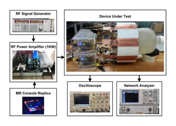
Test bench setup to check the performance of RF and electrical circuits.
Fig. 9.
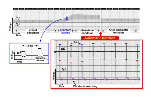
Measured test bench results of the fully automatic tuning and matching function: (a) reflected power level synchronized with the RF un-blank signal (str) (b) str signal (c) the enlarged output of RF power monitor circuit (d) coupled RF reflection signal at the RF coupler's output, and (e) the RF power monitor output according to (d).
Fig. 10.
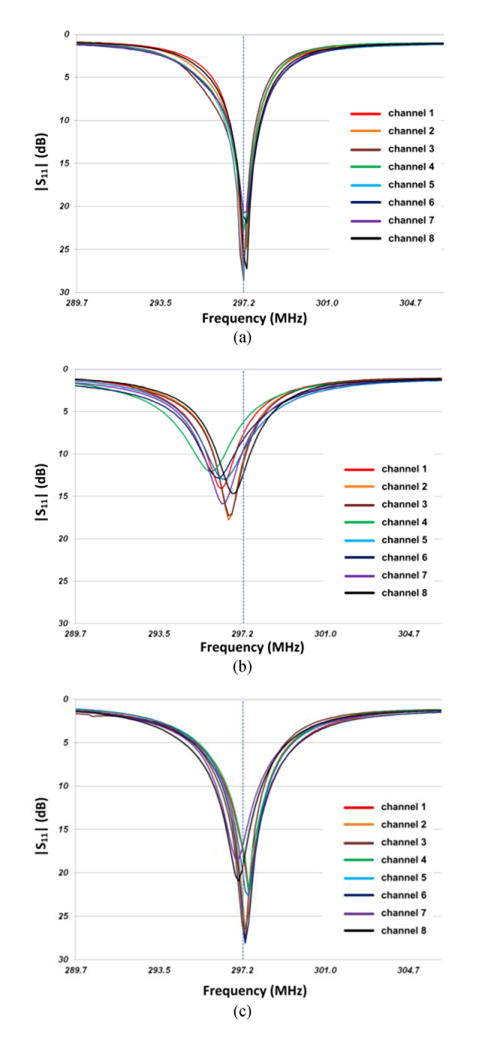
Measured reflection coefficient (S11): (a) the initially preset conditions without a phantom, (b) after a phantom loading, and (c) after the automatic tune and match at each channel.
Table I. RF Coil Element Characteristics and Performances.
| Channel number | Preset cond. | Loading effect | Improvement by auto-T&M | |||||||
|---|---|---|---|---|---|---|---|---|---|---|
| ➀ | ➁ | ➂ | ➃ | ➄ | ➅ | ➆ | ➇ | ➉ |

|
|
| |S11| (dB) |
Reflected RF power of ➀ (%) |
|S11| (dB) |
Reflected RF power of ➂ (%) |
Δ |S11|➂-➀ (dB) |
RF power loss by loading➃-➁ (%) |
|S11| (dB) |
Reflected RF power of ➆ (%) |
Δ |S11|➆-➂ (dB) |
RF transmission power improvement➃-➇ (%) |
|
| 1 | 27 | 0.2 | 7.9 | 16.3 | 19.1 | 16.1 | 19.3 | 1.2 | 11.4 | 15.1 |
| 2 | 25.3 | 0.3 | 11.1 | 7.7 | 14.2 | 7.4 | 22.3 | 0.6 | 11.2 | 7.1 |
| 3 | 28.4 | 0.1 | 11.6 | 6.8 | 16.8 | 6.7 | 25.6 | 0.3 | 14.0 | 6.6 |
| 4 | 22.7 | 0.5 | 6.4 | 23.1 | 16.3 | 22.6 | 18.2 | 1.5 | 11.8 | 21.6 |
| 5 | 28.2 | 0.2 | 9.9 | 10.3 | 18.3 | 10.2 | 19.3 | 1.2 | 9.4 | 9.2 |
| 6 | 21.1 | 0.8 | 8.4 | 14.4 | 12.7 | 13.6 | 23.7 | 0.4 | 15.3 | 14 |
| 7 | 20.7 | 0.9 | 9.8 | 10.4 | 10.8 | 9.5 | 17.2 | 1.9 | 7.3 | 8.5 |
| 8 | 25.7 | 0.3 | 12.7 | 5.3 | 13.0 | 5.1 | 19.6 | 1.1 | 6.9 | 4.2 |
V. MRI Experiments and Results
In the preliminary MRI experiment, the portable RF analyzer (Morris Instruments, Ottawa, Ont., Canada) is used to determine the tuned and matched condition inside the MR room. Fig. 11 shows the automatic tuned and matched MRI results according to RF power levels (8 W, 98 W, and 882 W) with a resolution phantom at 7 T. Since there is no artifact or distortion in images, the results demonstrate that the system works properly even at high power range (up to around 1 kW) and the strong magnetic field. Fig. 12 shows the comparison result between before and after the automatic function in MR images with a small bottle phantom. The automatic function after loading improves the RF signal penetration about 20% in SNR (combined transmitting and receiving signals). The performance of the automatic tuned and matched MR image was evaluated using the Gradient Recalled Echo (GRE) RF pulse sequence (resolution = 1×1 mm, repetition time = 150 ms, echo time = 6 ms, slice thickness = 5 mm) to acquire the slices in Fig. 13. The experimental set-up with the cylindrical phantom and the performance of each channel are presented in Fig. 13. Each channel has proper signal penetration, and the images do not have any significant defect or distortion. The stability of the system and its consistent performance were verified and the automatic function does not need any extra hardware or modification to connect the existing the MR scanner.
Fig. 11.
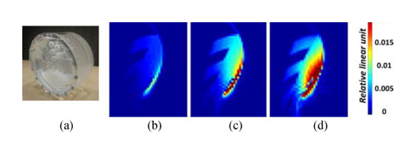
High power test: (a) a resolution phantom and MR images according to the RF input power (b) 20 Vrms (= 8 W), (c) 70 Vrms (= 98 W), and (d) 210 Vrms (=882 W)
Fig. 12.
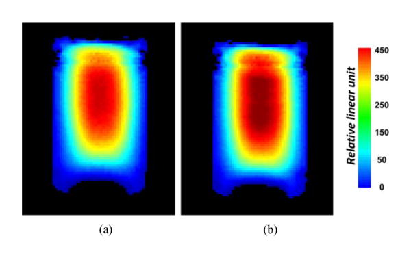
Experimental MR image results of the slices in the central region of a small cylindrical phantom; (a) before and (b) after automatic tuning and matching function.
Fig. 13.
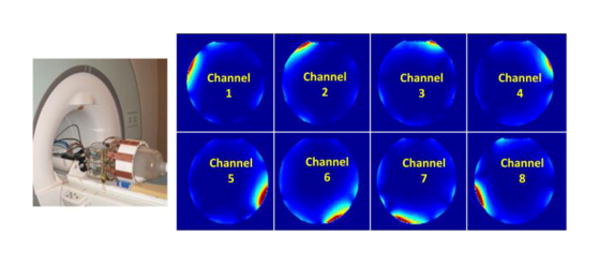
MR experimental set-up (left) and low flip angle gradient recalled echo images of each channel of the automatically tuned and matched 8-channel RF transceiver coil.
VI. Conclusion
This study has discussed the eight-channel automatic tuning and matching TEM RF transceiver head coil. The fully automated function offers the feasibility of overcoming the current time-consuming manual tuning and matching readjustments to correct the variation caused by the loading effect. It performs rapid and accurate impedance matching/frequency tuning resulting in the improved power transmission efficiency and higher SNR in MR images. This achievement can be a breakthrough for the current and future clinical RF coil technology.
Acknowledgments
This study was supported by the following U.S National Institute of Health (NIH) grants: P41 EB015894, R01 EB006835, 1R42EB013543-01 and R01 EB007327.
Biography

Sung-Min Sohn (S'11-M'13) received the B.S. and M.S. degrees from Korea University, Seoul, Korea, in 2002 and 2004, and the Ph.D degree from University of Minnesota, Minneapolis, MN, USA in 2013.
From 2004 to 2007, he was a circuit design engineer in Analog/Mixed circuit group at LG Electronics, Seoul, Korea, where he performed research on camera image processor and high speed serial link. He is currently a postdoctoral researcher in CMRR (center for magnetic resonance research) at university of Minnesota. His research is focusing on RF/analog circuits for MRI electronics and novel RF coil design.

Lance DelaBarre (M'13) received his B.S in Physics from North Dakota State University in 1995 and his Ph. D. in Biophysical Sciences and Medical Physics from the University of Minnesota in 2001. His research has focused on the challenges and rewards of high-field magnetic resonance (4 T, 7 T and 9.4 T) at the Center for Magnetic Resonance Research at the University of Minnesota. His areas of research have included RF pulse and sequence design, Magnetic Resonance Spectroscopy, High Resolution NMR, parallel transceivers and MRI RF coil design and testing

Anand Gopinath (S'64–M'65–SM'80–F'90–LF'02) received the Ph.D. and D.Eng. (higher doctorate) degrees by the University of Sheffield, U.K.
He was Reader in Electronics at the University College of North Wales (1978), and also held the Chair of Electronics in Chelsea College, now merged with King's College (1981–1982), University of London, London. He was Research Staff Member at MIT Lincoln Laboratory (1978–1981, 1982–1986), and then joined the University of Minnesota as Professor of Electrical and Computer Engineering. He was Director of the Microelectronics Laboratory (now the Nano Fabrication Center), University of Minnesota, in 1989–1994. He has performed research in the field of RF/microwaves, and published extensively in the areas of guided wave structures, devices and circuits, and has recently directed a project in the area of scattering. He has also worked in the Integrated Optics and Optoelectronics areas, and he has published on a variety of devices and modeling in the area. His most recent projects are on very fast Analog to Digital Converters in CMOS, electromagnetic wave scattering from high dielectric constant cubes and MRI RF coils.
He is Fellow of Optical Society of America and also Fellow of IET, London.

J. Thomas Vaughan (M'08) received the two B.S. degrees in electrical engineering and biology at Auburn University, Birmingham, AL, and the Doctoral degree in biomedical engineering from the University of Alabama at Birmingham, Birmingham, in 1993.
After receiving the degree, he joined Kennedy Space Center at NASA. Following the first Space Shuttle launch, he was recruited for a DOD project at Texas Instruments in Dallas before continuing his graduate education and employment at the University of Texas Southwestern. Here, he was the RF Engineer on a project to construct the first 2 T human NMR system begun in 1984.
In 1989, he took the post of the Chief Engineer for a University of Alabama Philips Research Labs consortium to build the first 4T system sited in the U.S. After receiving the Doctoral degree, he became an Assistant Professor at Harvard University and Assistant in Physics and Director of Engineering at the Massachusetts General Hospital NMR Center. Following a four year term at the MGH to help commission a 3 T system and launch a 7 T program, he accepted tenure at the University of Minnesota in 1999 where he continues his work at 4 T, 7 T, 9.4 T, and beyond. He is currently a Professor in the Departments of Radiology, Electrical Engineering and Biomedical Engineering, University of Minnesota, Minneapolis.
Dr. Vaughan administers the Engineering Core of the Center for Magnetic Resonance Research.
Contributor Information
Sung-Min Sohn, Email: sohnx021@umn.edu, Department of Electrical and Computer Engineering, University of Minnesota; Center for Magnetic Resonance Research (CMRR), University of Minnesota, Minneapolis, MN 55455 USA.
Lance DelaBarre, Email: dela0087@umn.edu, Center for Magnetic Resonance Research (CMRR), University of Minnesota, Minneapolis, MN 55454.
Anand Gopinath, Email: gopinath@umn.edu, Department of Electrical and Computer Engineering, University of Minnesota, Minneapolis, MN 55455 USA.
John Thomas Vaughan, Email: vaugh020@umn.edu, Department of Electrical and Computer Engineering and with the Center for Magnetic Resonance Research (CMRR), University of Minnesota, Minneapolis, MN 55455 USA.
References
- 1.Vaughan JT, DelaBarre L, Snyder C, Tian J, Akgun C, Shrivastava D, Liu W, Olson C, Adriany G, Strupp J, Andersen P, Gopinath A, van de Moortele PF, Garwood M, Ugurbil K. 9.4T human MRI: Preliminary results. Magn Reson Med. 2006;56:1274–1282. doi: 10.1002/mrm.21073. [DOI] [PMC free article] [PubMed] [Google Scholar]
- 2.Ugurbil K, Garwood M, Ellermann J, Hendrich K, Hinke R, Hu X, Kim SG, Menon R, Merkle H, Ogawa S. Imaging at high magnetic .ields: initial experiences at 4T. Magn Reson Q. 1993;9(4):259–277. [PubMed] [Google Scholar]
- 3.Vaughan JT, Garwood M, Collins CM, Liu W, DelaBarre L, Adriany G, Andersen P, Merkle H, Goebel R, Smith MB, Ugurbil K. 7T vs. 4T: RF power, homogeneity, and signal-to-noise comparison in head images. Magn Reson Med. 2001;46:24–30. doi: 10.1002/mrm.1156. [DOI] [PubMed] [Google Scholar]
- 4.Shajan G, Hoffmann J, Budde J, Adriany G, Ugurbil K, Pohmann R. Design and evaluation of an RF front-end for 9.4 T human MRI. Magn Reson Med. 2011;66:594–602. doi: 10.1002/mrm.22808. [DOI] [PubMed] [Google Scholar]
- 5.Ibrahim T, Lee R, Baerlein B, Abduljalil A, Zhu H, Robitaille P. Effect of RF coil excitation on field inhomogeneity at ultra high fields: A field optimized TEM resonator. Magn Reson Med. 2001;19:1339–1347. doi: 10.1016/s0730-725x(01)00404-0. [DOI] [PubMed] [Google Scholar]
- 6.Ugurbil K. Magnetic Resonance Imaging at Ultrahigh Fields. Biomedical Engineering, IEEE T Biomed Eng. 2014 May;61(5):1364–1379. doi: 10.1109/TBME.2014.2313619. [DOI] [PMC free article] [PubMed] [Google Scholar]
- 7.Vaughan JT, Griffiths John R. RF Coils for MRI. Wiley; 2012. [Google Scholar]
- 8.Sohn SM, DelaBarre L, Vaughan JT, Gopinath A. 8-Channel RF head coil of MRI with automatic tuning and matching. IEEE MTT-S International Microwave Symposium Digest. 2013 [Google Scholar]
- 9.Vaughan JT, Adriany G, Snyder CJ, Tian J, Thiel T, Bolinger L, Liu H, DelaBarre L, Ugurbil K. Efficient high-frequency body coil for high-field MRI. Magn Reson Med. 2004;52:851–859. doi: 10.1002/mrm.20177. [DOI] [PubMed] [Google Scholar]
- 10.De Mingo J, Valdovinos A, Crespo A, Navarro D, Garcia P. An RF electronically controlled impedance tuning network design and its application to an antenna input impedance automatic matching system. IEEE Trans Microw Theory Techn. 2004;52:489–497. [Google Scholar]
- 11.Scanlon WG, Evans NE, Rollins M. Antenna-body interaction effects in a 418 MHz radio telemeter for infant use. Engineering in Medicine and Biology Society, 1966. Bridging Disciplines for Biomedicine; Proceedings of the 18th Annual International Conference of the IEEE; 1996; pp. 278–279. [Google Scholar]
- 12.Sankey L, Popovic Z. Adaptive tuning for handheld transmitters. IEEE MTT-S International Microwave Symposium Digest. 2009:225–228. [Google Scholar]
- 13.Pavan M, aKP P. A modular automatic matching network system. Proc 18th Int Soc for Magnetic Resonance in Medicine Meeting. 2010:647. [Google Scholar]
- 14.Beck BL, W S, Turner WJ, Bashirullah R, Mareci TH. High Q Reactive Network for Automatic Impedance Matching. Proc 19th Int Soc for Magnetic Resonance in Medicine Meeting. 2011:1853. [Google Scholar]
- 15.Hwang F, Hoult DI. Automatic probe tuning and matching. Magn Reson Med. 1998;39(2):214–222. doi: 10.1002/mrm.1910390208. [DOI] [PubMed] [Google Scholar]
- 16.Pérez de Alejo R, Garrido C, Villa P, Rodriguez I, Vaquero JJ, Ruiz-Cabello J, Cortijo M. Automatic tuning and matching of a small multifrequency saddle coil at 4.7 T. Magn Reson Med. 2004;51:869–873. doi: 10.1002/mrm.20045. [DOI] [PubMed] [Google Scholar]
- 17.Venook RD, Hargreaves BA, Gold GE, Conolly SM, Scott GC. Automatic tuning of flexible interventional RF receiver coils. Magn Reson Med. 2005;54:983–993. doi: 10.1002/mrm.20616. [DOI] [PubMed] [Google Scholar]
- 18.Muftuler LT, Gulsen G, Sezen KD, Nalcioglu O. Automatic Tuned MRI RF Coil for Multinuclear Imaging of Small Animals at 3T. J Magn Reson. 2002;155:39–44. doi: 10.1006/jmre.2002.2510. [DOI] [PubMed] [Google Scholar]
- 19.Madic J, Bretchko P, Shuyun Z, Shumovich R, McMorrow R. Accurate power control technique for handset PA modules with integrated directional couplers. Radio Frequency Integrated Circuits (RFIC) Symposium. 2003:715–718. [Google Scholar]
- 20.Caverly RH, Hiller G. Establishing the minimum reverse bias for a p-i-n diode in a high-power switch. IEEE Trans Microw Theory Techn. 1990 Dec;38(12):1938, 1943. [Google Scholar]


