Abstract
Purpose
Prostate needle biopsy is a commonly performed procedure since it is the most definitive form of cancer diagnosis. Magnetic resonance imaging (MRI) allows target-specific biopsies to be performed. However, needle placements are often inaccurate due to intra-operative prostate motion and the lack of motion compensation techniques. This paper detects and determines the extent of tissue displacement during an MRI-guided biopsy so that the needle insertion plan can be adjusted accordingly.
Methods
A multi-slice-to-volume registration algorithm was developed to align the pre-operative planning image volume with three intra-operative orthogonal image slices of the prostate acquired immediately before needle insertion. The algorithm consists of an initial rigid transformation followed by a deformable step.
Results
A total of 14 image sets from 10 patients were studied. Based on prostate contour alignment, the registrations were accurate to within 2 mm.
Conclusion
This algorithm can be used to increase the needle targeting accuracy by alerting the clinician if the biopsy target has moved significantly prior to needle insertion. The proposed method demonstrated feasibility of intra-operative target localization and motion compensation for MRI-guided prostate biopsy.
Keywords: Prostate biopsy, Target localization, MRI-guidance, Image registration
Introduction
Prostate cancer is the most commonly diagnosed cancer and the second most common cause of cancer death for American men. In 2012, there were an estimated 241,740 new cases and 28,170 deaths of this disease [1]. The existence and extent of cancer are diagnosed by needle biopsy and histological analysis of the tissue samples. Each year, approximately 1.5 million prostate biopsies are performed in the USA [1]. Two-dimensional (2D) transrectal ultrasound (TRUS) is the current standard imaging modality for biopsy guidance. However, TRUS provides limited image quality and diagnostic accuracy. Typically, substructures or lesions within the prostate are not visible; therefore, systematic sampling of the upper, mid, and lower areas of the left and right sides of the gland is performed. Studies have shown that this method only has a detection rate of 20–40 % [2,3]. Even though there have been many attempts to improve the standard 2D TRUS biopsy, cancers are still routinely being missed [4–6].
Magnetic resonance imaging (MRI) provides an alternative guidance to biopsy. MRI has high soft tissue contrast and provides clear visualization of the prostate along with its substructures, such as the peripheral zone, where most of cancer occurs [2]. It allows suspicious lesions to be identified so that target-specific biopsies can be performed. MRI has not been widely adopted for prostate interventions due to its limited availability and high cost. Nonetheless, it plays an important part in research and remains as an alternative for patients that are not suitable for TRUS procedures or have rising prostate specific antigen (PSA) levels but repeated negative TRUS-guided biopsy results. Due to the limited space in conventional closed-bore scanners and the magnetic fields, special equipment and guidance software are required.
Many systems were developed for MRI-guided prostate biopsy [7,8]. However, the current clinical biopsy protocols for these systems do not take into consideration of possible intra-operative prostate motion and deformation during the procedure due to both patient movement and mechanical forces exerted by the biopsy system. The prostate is a soft tissue organ attached only by connective tissues. Therefore, it can shift, rotate, and deform differently from the surrounding structures. Biomechanical modeling of the organ behavior during biopsy is extremely complex since its parameters and material properties can vary between patients. Our previous study [9] found a mean prostate centroid motion of 8.7 mm (range 0.2–34.7 mm) during MRI-guided transperineal biopsies based on 538 images. Xu et al. [10] reported a mean prostate displacement of 5.2 mm (range 0.9–18 mm) for 90 needle insertions in MRI-guided transrectal biopsy, and 28 % of the biopsy errors exceeded 5 mm, which corresponds to the radius of a clinically significant tumor (0.5 cc) [11].
Intra-operative prostate motion and deformation can cause inaccurate needle placement during biopsy [10]. As a result, malignant tumors can be missed, which in turn will lead to an increased number of repeated biopsies and delaying of treatment. Therefore, it is important to incorporate motion tracking techniques into the clinical procedure in order to improve the overall needle targeting accuracy. The ultimate goal would be to track both the intended biopsy target and the needle in real time. However, as the first step, we focus on estimating the target position and developing a motion detection method to warn the clinician if there is large displacement of the intended biopsy target prior to needle insertion. If possible, the clinician can then adjust the needle insertion plan to compensate for this motion. Otherwise, a new planning scan can be acquired, and the insertion plan can be made based on this new image. Such methods need to be integrated into imaging protocols available on any regular MRI scanner. Since multi-slice 2D imaging series (volumetric MRI) acquisition typically takes around a minute, methods that require multiple of these image series to locate the biopsy targets are not ideal. As an alternative, intermittent acquisition of only a few image slices can be used to obtain the required information of a full image volume. This process takes considerably less time, since a single image slice can usually be obtained in only a few seconds.
It is important to note that the main goal of this paper is to support the many already existing MRI-guided robotic intervention systems rather than proposing it over the TRUS-guided prostate procedures.
Related works
There are numerous methods developed for tracking the prostate during biopsy. However, most of these methods use ultrasound images or focus on ultrasound and MRI fusion. In the context of MR image-based prostate registration using multiple image slices, there are three closely relevant papers by Fei et al. [12], Gill et al. [13], and Tadayyon et al. [14].
Fei et al. developed a single-slice-to-volume rigid registration algorithm for radio-frequency thermal ablation of prostate cancer. The pre-operative image volumes and intra-operative image slices in transverse, sagittal, and coronal planes were acquired from 3 volunteers using a conventional 1.5T scanner and a clinical 0.2T C-arm open MRI scanner, respectively. The image slices from each volunteer were individually registered to the corresponding MRI volumes. A total of 450 registrations were performed, and it was found that images in the transverse orientation produced the best results based on comparison with volume-to-volume registration. The algorithm used two similarity metrics and featured a multi-resolution approach with an automatic restart. The restart applied a random perturbation to the last transformation parameters found by the registration in order to to escape the potential local optima of the cost function.
Gill et al. addressed the problem of local extremes and the inefficiency in Fei’s optimization. The need for restarting the registration was eliminated by using a multi-resolution registration based on a region of interest. Due to insufficient information from a single transverse image slice, Gill’s implementation incorporated a simulated sagittal slice centered at the prostate to improve the registration result.
Both studies mentioned above do not take into consideration of prostate deformation, which is a known issue during biopsy. Tadayyon et al. proposed a non-rigid method to account for prostate deformation in addition to rigid motion. The algorithm can handle multiple image slices with different orientations all at once without using the multi-resolution scheme. Simulated intra-operative image slices were pasted into an empty volume (sparse volume construction), and 3D-to-3D image-based registration was performed. The study showed that three image slices in the transverse, sagittal, and coronal plane were sufficient enough to be used for image registration purposes. It is important to note that this exploratory study only used simulated image slices based on the high-resolution image volume. Real clinical intra-operative image slices can be quite different to these simulated images since a different imaging protocol is often used. Furthermore, the mean execution time for the registrations was over 16 min, which is not clinically practical.
This paper reports a multi-slice-to-volume deformable registration method that aligns the pre-operative planning image volume with three intra-operative orthogonal image slices acquired immediately before needle insertion. The method was tested on clinical images provided by Brigham and Women’s Hospital in Boston, MA, USA. We present several major improvements to Tadayyon’s work. These include:
Method validation on actual clinical data instead of just simulated images.
Ability to handle image slices in any orientation rather than just transverse, sagittal, and coronal.
Elimination of the sparse volume construction step, and register the image slices directly to the planning volume without any resampling.
Improved method validation techniques.
Region of interest is no longer needed in the rigid step.
Incorporation of image pre-processing for MRI bias field correction.
The remainder of this paper presents the detailed methodology and validation of our multi-slice-volume registration using clinical images from MRI-guided transperineal prostate biopsy.
Methods
Our objective is to detect cases where large intra-operative motion is present prior to needle insertion so that either modifications of the original biopsy plan can be made or reacquisition of the planning volume can be performed to compensate for the target displacement. By registering the intra-operative orthogonal image slices with the pre-operative planning volume, the existence of prostate motion and deformation can be determined.
Image acquisition
A custom setup and software were developed at Brigham and Women’s Hospital to perform MRI-guided transperineal biopsy without moving the patient out of the scanner [15]. The setup consists of a specially designed tabletop and a needle guiding template that gives clinicians access to the perineum of the patient at the imaging position.
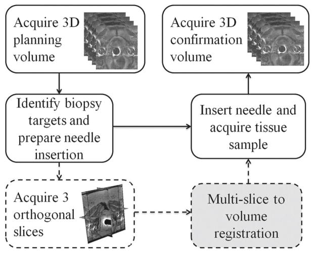
The remainder of this section describes the portion of the clinical protocol that is relevant to the acquisition of the images used in this study. First, the patients were sedated and immobilized on the table top with velcro wraps. Then, they were placed into a wide bore Siemens Magnetom Verio 3T scanner in supine position, and a 4-min T2-weighted multi-slice 2D transverse imaging series covering the whole prostate gland were taken with TSE sequence. This was used as the pre-operative planning volume where potential biopsy targets in scanner coordinate system were selected by the clinicians. Immediately before the needle insertion, a quick 18-s scan of 3 orthogonal image slices of the prostate in transverse, sagittal, and coronal plane was collected with HASTE localizer sequence. The clinicians then proceeded with the needle placement. Finally, another multi-slice transverse T2-weighted sequence (1-min scan) was acquired with the needles in place to confirm its placement. Figure 1 illustrates the overall clinical workflow.
Fig. 1.
Clinical workflow of the image acquisitions during MRI-guided prostate biopsy. The solid lines indicate the standard biopsy procedure, and the dashed lines represent the additional orthogonal image slice acquisition specific to our study. The gray box is the motion compensation registration method we propose to incorporate
The process starting from the initial acquisition of the pre-operative planning volume to the final needle confirmation image takes an average of 90 min. During this time, intra-operative motion of the prostate may occur. If this motion is large, then the biopsy target locations that were chosen based on the pre-operative planning volume would no longer be valid.
Image registration
The images used in the multi-slice-to-volume registration were the pre-operative planning T2-weighted volume (multi-slice 2D imaging series) and the intra-operative orthogonal image slices. All images were first pre-processed to correct for non-uniform intensity caused by field inhomogeneities. Since the biopsy procedure at Brigham and Women’s Hospital did not include the use of an endorectal imaging coil, the pre-processing step did not have a large effect on their images. However, this is provided as an optional step in the algorithm so that it can be applied to a broader range of images, which are taken with the endorectal coil. N4ITK (Nicks N3 Insight Toolkit) implementation for MRI bias field correction [16] was used because it does not require expert supervision, user interaction, or training, and only has a few user-defined parameters. The two most important parameters are bias full width at half maximum (BWHM) and noise. BWHM defines the Gaussian that estimates the bias field, and noise specifies the Wiener filter used for field estimation. Values of 0.5 for BWHM and 0.01 for noise were found to work the best with our clinical images.
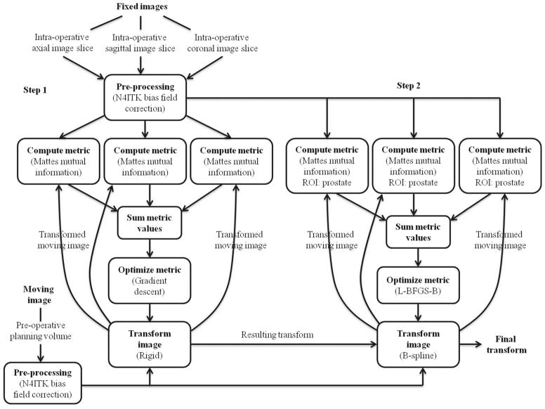
After bias field correction, a multi-slice-to-volume registration algorithm (Fig. 2) was developed using ITK [17] to determine the transformation between the pre-operative planning volume (V ) and intra-operative orthogonal image slices (S) acquired just prior to needle insertion. The fixed and moving images of the registration were S and V, respectively. Due to imaging protocol differences, the same tissue structures have different intensities on the fixed and moving images; therefore, mutual information was chosen as the metric for evaluating image alignment. Since each of the three orthogonal image slices needs to be registered to the planning volume, the mutual information metric was modified so that it calculates the sum of these three metrics.
Fig. 2.
Workflow of the multi-slice-to-volume registration between the pre-operative planning volume and intra-operative image slices
The algorithm consists of an initial rigid registration using the entire image to correct for gross prostate motion in coherence with the device and patient. To recover tissue deformation, a B-spline deformable registration with grid size of 5 × 5 × 5 was performed using only the prostate as the region of interest (ROI). The ROIs were specified as rectangles by manually selecting the starting positions and sizes of the prostate on the fixed images. The B-spline transform is able to represent a typical prostate deformation. In addition, it is fast to compute, and the number of grid points and its maximum displacement can be used to keep the deformation field under control during registration. A gradient descent optimizer was implemented for the versor rigid 3D transform, and a L-BFGS-B (Limited-memory Broyden–Fletcher–Goldfarb–Shannon with simple bounds) optimizer was used for the deformable component. The entire process is fully automatic after the initial user selection of the ROI. The detailed workflow is shown in Fig. 2. One of the main implementation challenges was to tune a set of registration parameters that would work the best for our imaging sequence. These parameters were chosen based on both speed and accuracy of the registration result.
Registration validation
Experiment 1: Simulated images
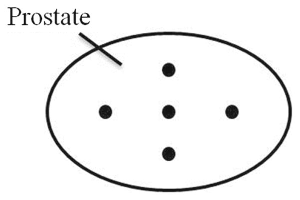
This experiment was conducted to simply test whether the algorithm works by providing some ground truth. To validate the accuracy of rigid registration, we first simulated intra-operative orthogonal image slices from the pre-operative planning volume. Three empty image slices in transverse, sagittal, and coronal plane were created, and the pixel information from the planning volume was resampled into the slices. These simulated images were then registered back to the planning volume with a random initial transform that was set to a range of ±20 mm translation and ±10° rotation along each of the three axis. If the rigid registration works properly, it should correct for this initial misalignment and produce a transformation matrix that is close to the identity. Five points in the center, left, right, top, and bottom of the prostate (Fig. 3) were chosen on the fixed images, and its target registration error (TRE) was calculated. The TRE was defined as the distance between one of the chosen points and its reconstructed point. The process was repeated 5 times for each of the 11 images we have, and all of the TREs with its corresponding initial misalignment were recorded.
Fig. 3.
The arrangement of 5 ground truth points chosen on the prostate
The accuracy of deformable registration was also tested using simulated intra-operative orthogonal image slices. We selected two corresponding sets of five points on the planning volume. The second set of points was randomly displaced ±5 mm from the first set. A Landwarp landmark deformable registration by Plastimatch was performed in 3D Slicer [18], a free open source software package for visualization and image analysis. The planning volume was warped based on the displacements of the two point sets using thin-plate spline transform and radial basis function [19]. The reason we chose to warp the planning volume instead of the image slices is simply because the Landwarp landmark deformable registration works better with volumetric images. The three orthogonal image slices were then generated using the warped volume and were registered to back to the original planning volume using the B-spline deformable algorithm that we developed. The displacement vectors of the five points were computed and compared with the ground truth. The process was repeated once for each of the 11 images, and all TREs were calculated and recorded as an accuracy assessment.
Experiment 2: Clinical images
For the clinical images, a different validation method was applied since the exact correspondence of the prostate anatomy between different images cannot be easily identified. The fixed and moving images were overlaid before and after registration, and the prostate alignment (including contours, which were manually drawn and validated by radiologist) was examined by observing the changes of images while fading (fusing them with different weights) between them multiple times. This process was performed interactively in 3D Slicer. After the alignment validation, the transformations produced by the proposed algorithm were used as part of the ground truth calculation for further testing (Eq. 1). The previous validation procedures used on simulated images were repeated on the actual clinical images to test the robustness of the registration.
| (1) |
where TGTreg is the transformation between the clinical image pairs estimated by the proposed registration, TGTdisp is the randomly generated initial misalignment (rigid: ±20 mm translation and ±10° rotation. Deformable: ±5 mm warping), Treg is the transformation produced by the proposed registration between the clinical image pairs with know initial misalignment, and p is a sample point within the prostate.
Experiment 3: Multi-slice-to-volume versus volume-to-volume
To determine whether the multi-slice-to-volume registration is sufficient in capturing prostate motion intra-operatively, we compared it with volume-to-volume registration. The needle confirmation image volume (Fig. 1) for each biopsy was registered with its corresponding planning volume using an initial rigid alignment of the whole image, followed by a B-spline deformable transform with only the prostate as region of interest. This is similar to what Xu et al. [10] proposed for the registration of pre- and post-needle insertion volumetric MRIs for transrectal prostate biopsy. The results were compared to the multi-slice-to-volume registration between the planning volume and simulated intra-operative orthogonal image slices generated from the needle confirmation volume. The 5 points on the prostate (Fig. 3) were selected on the fixed (needle confirmation) images and were transformed by the results obtained from both registrations separately. The distances between targets from volume-to-volume registration and multi-slice-to-volume registration were also calculated.
Table 1 summarizes all of the images and methods used for these three registration validation experiments.
Table 1.
Registration validation experiments summary
| Exp. | Registration | Fixed image(s) | Moving image |
|---|---|---|---|
| 1a | Rigid, MSV | 3 Orthogonal slices resampled from planning volume | Planning volume |
| 1b | Deformable, MSV | 3 Orthogonal slices resampled from warped planning volume | Planning volume |
| 2a | Rigid, MSV | 3 Orthogonal slices | Planning volume |
| 2b | Rigid + deformable, MSV | 3 Orthogonal slices | Warped planning volume |
| 3a | Rigid + deformable, MSV | 3 Orthogonal slices resampled from needle confirmation volume | Planning volume |
| 3b | Rigid + deformable, VV | Needle confirmation volume | Planning volume |
Exp. experiment, MSV multi-slice-to-volume, VV volume-to-volume
Results
A total of 14 planning volume and orthogonal image slices pairs from 10 patients were obtained from the Brigham and Women’s Hospital and were used in our study.
All resulting images after the multi-slice-to-volume registration were overlaid with its corresponding fixed images in 3D Slicer. Based on prostate contour evaluations, the maximum misalignments were all under 2 mm. An example of the image overlay before and after registration of the clinical image pairs is shown in Fig. 4.
Fig. 4.
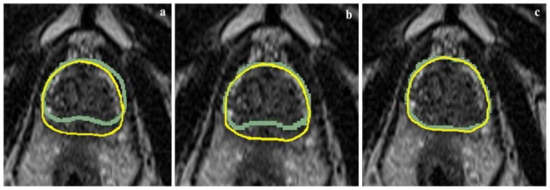
Examples of clinical image prostate contour overlay in the transverse plane. Each of the three images is copies of the same fixed image overlaid with the contours from the moving image a before registration, b after rigid registration, and c after deformable registration
Values of the optimizer parameters for both rigid and deformable steps are listed in Tables 2 and 3, respectively.
Table 2.
Gradient descent optimizer parameters for the rigid registration step
| Parameters | Value |
|---|---|
| Max step length | 2 |
| Min step length | 0.01 |
| Relaxation factor | 0.9 |
| Max number of iterations | 250 |
Table 3.
L-BFGS-B optimizer parameters for the deformable registration step
| Parameters | Value |
|---|---|
| Convergence factor | 1 × 10¹² |
| Projected gradient tolerance | 1 × 10⁻⁷ |
| Number of corrections | 10 |
| Max number of iterations | 250 |
| Upper and lower bound | ±5 |
The mean execution time for rigid and deformable registrations was 3.3 and 31 s, respectively, on an Intel Core i7-2600K processor running at 3.40GHz. This is summarized in Table 4. Furthermore, the optional N4ITK bias field correction only takes less than 2 s to complete, and the user-defined ROI can be completed within 5 s.
Table 4.
Summary of execution time statistics for multi-slice-to-volume registration with clinical images
| Rigid (s) | Deformable (s) | |
|---|---|---|
| Mean | 3.3 | 31 |
| Range | 2.5–4.2 | 13.7–68.1 |
| SD | 0.6 | 14.8 |
The difference between rigid and deformable registrations was studied. The results were significantly different ( p = 7.0 × 10⁻¹⁰).
Registration validation
Experiment 1: Simulated images
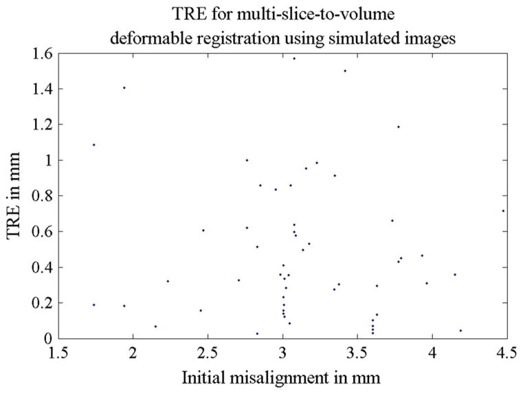
The accuracy of both rigid and deformable registrations was studied separatively using simulated intra-operative orthogonal image slices. For rigid registration, a mean TRE of 0.1 mm was found. All TREs from 55 simulations are shown in Fig. 5, and Table 5 provides a summary of the TRE statistics for the rigid step. For the deformable part of the algorithm, the mean TRE was 0.5 mm. This is summarized in Table 6. Figure 6 shows all TREs from the 11 experiments and its corresponding initial misalignments. The prostate contour alignment before and after deformable registration using the simulated images is shown in Fig. 7.
Fig. 5.
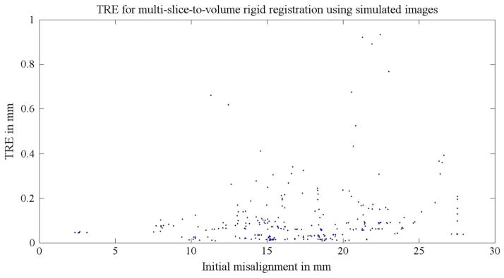
TREs for Experiment 1a: the 55 multi-slice-to-volume rigid registrations using simulated images. The simulated images were undistorted (no deformation was applied). A random initial transform of ±20 mm translation and ±10° rotation along each axis were set to the registrations. The distance between the initial target and the ground truth target was defined as the initial misalignment
Table 5.
TRE statistics for Experiment 1a: multi-slice-to-volume rigid registration between the planning volume and simulated intra-operative orthogonal image slices
| Rigid registration TRE (mm) | |
|---|---|
| Mean | 0.1 |
| Range | 0–0.9 |
| SD | 0.1 |
The simulated images were undistorted (no deformation was applied)
Table 6.
TRE statistics for Experiment 1b: multi-slice-to-volume deformable registration between the planning volume and simulated intra-operative orthogonal image slices
| Deformable registration TRE (mm) | |
|---|---|
| Mean | 0.5 |
| Range | 0–1.6 |
| SD | 0.4 |
Registration validation
Fig. 6.
TREs for Experiment 1b: the 11 multi-slice-to-volume deformable registrations using simulated images. The simulated images were warped ±5 mm based on two sets of manually defined points using Landwrap landmark deformable registration in 3D Slicer
Fig. 7.
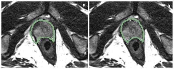
Examples of prostate contour overlay on the simulated fixed transverse image slice a before registration and b after deformable registration
Experiment 2: Clinical images
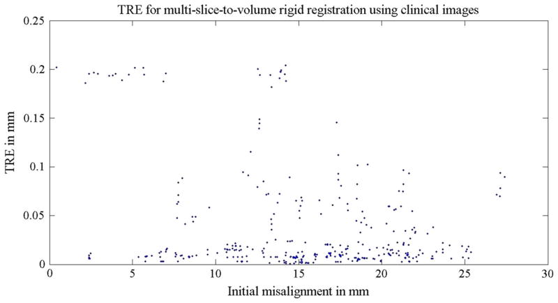
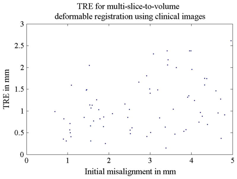
Using the original registration results from the actual clinical image pairs as the ground truth (Eq. 1), we further tested the accuracy and robustness of the algorithm with only clinical images. In the rigid step, a random initial transform of ±20 mm translation and ±10° rotation along each of the three axis was set. A total of 70 registrations were performed on 14 image pairs, and the TREs were all below 0.2 mm. Table 7 and Fig. 8 contains more detailed information regarding TRE statistics for the rigid step. In the deformable step, the planning volumes were warped ±5 mm and were then registered to the three orthogonal clinical image slices using the two-step algorithm. The final mean TRE was found to be 1.1 mm for 14 registrations. This is summarized in Table 8 and Fig. 9.
Table 7.
TRE statistics for Experiment 2a: multi-slice-to-volume rigid registration between the planning volume and clinical intra-operative orthogonal image slices
| Rigid registration TRE (mm) | |
|---|---|
| Mean | 0.04 |
| Range | 0–0.2 |
| SD | 0.1 |
Fig. 8.
TREs for Experiment 2a: the 70 multi-slice-to-volume rigid registrations using clinical images. A random initial transform of ±20 mm translation and ±10° rotation along each axis was set to the registrations. The distance between the initial target and the ground truth target was defined as the initial misalignment
Table 8.
TRE statistics for Experiment 2b: multi-slice-to-volume deformable registration between the planning volume and clinical intra-operative orthogonal image slices
| Rigid registration step TRE (mm) | Deformable registration step TRE (mm) | |
|---|---|---|
| Mean | 3.7 | 1.1 |
| Range | 1–6.6 | 0.1–2.6 |
| SD | 1.4 | 0.6 |
Fig. 9.
TREs for Experiment 2b: the 14 multi-slice-to-volume deformable registrations using clinical images. The image volumes were warped ±5 mm based on two sets of manually defined points using Landwrap landmark deformable registration in 3D Slicer
Experiment 3: Multi-slice-to-volume versus volume-to-volume
The results of multi-slice-to-volume registration between the needle confirmation images and the planning volumes were compared with volume-to-volume registration. The target distances of the two algorithms are plotted in Fig. 10 (mean: 1 mm, range 0.1–2.7 mm, standard deviation: 0.7 mm).
Fig. 10.
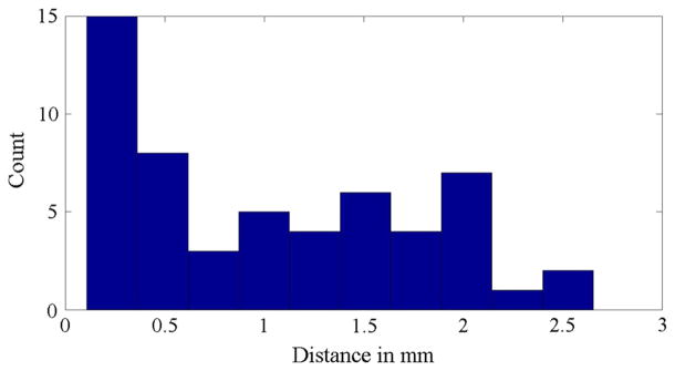
Experiment 3: Histogram of the target distances between multi-slice-to-volume and volume-to-volume registration
Discussion
The radius of a clinically significant tumor is 5 mm [11]; hence, a registration error less than 5 mm is considered as sufficiently accurate for needle placement purposes. In addition, it is also less than the slice spacing (3.6 mm) of our data set from Brigham and Women’s Hospital.
It is important for the algorithm to be able to handle a large variety of MR images with different intensities and initial misalignments. We performed several validation methods to ensure the accuracy and robustness of our algorithm. Since the exact correspondence of the prostate anatomy cannot be easily identified in clinical MR images, typical validation methods such as using landmarks to evaluate the accuracy of our registration are not applicable. Therefore, we generated simulated intra-operative orthogonal image slices from the pre-operative planning volume in order to obtain ground truth.
With regard to the actual clinical images, the image overlay after registration showed obvious improvements to the initial contour alignment before registration (Fig. 4). The registration errors based on prostate contours were also clinically acceptable (less than 5 mm). The alignment of other prostate structures was also visually inspected in 3D Slicer. Even though the exact biopsy target position cannot be determined, the smooth B-spline interpolation can give an accurate estimate of its location as evident by the results of our validation methods. The fact that the multi-slice-to-volume registration was able to produce results that were less than 3 mm different from that of the volume-to-volume registration further indicates the reliability of our algorithm.
Since the patients were sedated, intra-operative patient motion was limited. Therefore, the initial prostate misalignments before registration were small for the Brigham and Women’s Hospital data. However, this is not the case for transrectal biopsies. The registration results from both real and simulated images demonstrated that our algorithm was able to recover initial rigid misalignments (±20 mm translation and ±10° rotation) and correct for prostate deformation (±5 mm warping of the images) with less than 1.1 mm accuracy on average, which is well under the 5 mm upper limit mentioned earlier. The numerical ranges for the ground truth initial misalignment and warping were chosen because they are large enough to cover most of the intra-operative tissue motion and deformation based on our previous study of prostate motion during biopsy [10].
Clinically, a processing time of approximately 1 min to compute the current biopsy target position prior to needle insertion is reasonable. The mean execution time of 34.3 + 7 s (registration + manual ROI selection and optional bias correction) fulfills this time requirement.
To summarize, we developed an image-based multi-slice-to-volume registration algorithm for MRI-guided prostate biopsy to detect cases with large intra-operative prostate motion prior to needle insertion. Contour alignments were used to validate the registration results of clinical images, and both simulated and clinical images were used for quantitative evaluation of the algorithm. All registration errors were well below the radius of a clinically significant tumor (5 mm) and can be considered as clinically acceptable. The overall execution time for biopsy target displacement computation was also short enough for clinical practice.
In conclusion, the quick image slice acquisition method can be incorporated with any regular MRI scanner, and the multi-slice-to-volume registration can be used to alert the clinician if the biopsy target has moved significantly after the planning volume acquisition and before needle insertion. Decisions can be made either to compensate the insertion plan by the results of the slice-to-volume registration or to reacquire another set of planning images. The latter method takes more time, and we hope in most cases it will not be necessary and the registration result can be used for motion compensation instead. Furthermore, the registration method can also be used when a quick feedback loop is essential, such as in real-time image guided needle steering, which can decrease the errors caused by needle deflection. Currently, this method adds an extra step to the clinical protocol in order to increase the needle targeting accuracy. In the future, needle tracking can be included to increase the speed of the procedure by reducing the need of the volumetric needle confirmation imaging step. We expect further testing with more image data and possible future integration of this methodology into clinical practice so that we can make a tangible difference in the lives of patients who are not suitable for or need more advanced system than the standard TRUS-guided biopsy.
Acknowledgments
This work was supported by Cancer Care Ontario Canada, Canadian Ontario Graduate Scholarship, U.S. NIH R01CA111288 and P41EB015898.
The authors would like to thank Janice Fairhurst, MR technologist from Advanced Multi-modality Image Guided Operating (AMIGO) Suite in Brigham and Women’s Hospital for the image data collection.
Footnotes
Conflict of interest None.
Contributor Information
Helen Xu, Email: helen@cs.queensu.ca, School of Computing, Queen’s University, Kingston, Canada.
Andras Lasso, School of Computing, Queen’s University, Kingston, Canada.
Andriy Fedorov, Brigham and Women’s Hospital, Boston, MA, USA.
Kemal Tuncali, Brigham and Women’s Hospital, Boston, MA, USA.
Clare Tempany, Brigham and Women’s Hospital, Boston, MA, USA.
Gabor Fichtinger, Email: gabor@cs.queensu.ca, School of Computing, Queen’s University, Kingston, Canada.
References
- 1.American Cancer Society. [Accessed 9 Jan 2013];Cancer facts and figures. 2012 www.cancer.org.
- 2.Tempany C, Straus S, Hata N, Haker S. MR-guided prostate interventions. J Magn Reson Imaging. 2008;27:356–367. doi: 10.1002/jmri.21259. [DOI] [PMC free article] [PubMed] [Google Scholar]
- 3.Kronz J, Allan C, Shaikh A, Epstein J. Predicting cancer following a diagnosis of high grade prostatic intraepithelial neoplasia on needle biopsy: data on men with more than one follow-up biopsy. Am J Surg Pathol. 2001;25(8):1079–1085. doi: 10.1097/00000478-200108000-00014. [DOI] [PubMed] [Google Scholar]
- 4.Norberg M, Egevad L, Holmberg L, Sparen P, Norlen B, Busch C. The sextant protocol for ultrasound-guided core biopsies of the prostate underestimates the presence of cancer. Urology. 1997;50(4):562–566. doi: 10.1016/S0090-4295(97)00306-3. [DOI] [PubMed] [Google Scholar]
- 5.Terris M, Wallen E, Stamey T. Comparison of mid-lobe versus lateral systematic sextant biopsies in detection of prostate cancer. Urol Int. 1997;59:239–242. doi: 10.1159/000283071. [DOI] [PubMed] [Google Scholar]
- 6.Terris M. Strategies for repeat prostate biopsies. Curr Urol Rep. 2009;10(3):172–178. doi: 10.1007/s11934-009-0030-y. [DOI] [PubMed] [Google Scholar]
- 7.Pondman K, Futterer J, Haken BT, Kool L, Witjes J, Hambrock T, Macura K, Barentsz J. MR-guided biopsy of the prostate: an overview of techniques and a systematic review. Eur Urol. 2008;54(3):517–527. doi: 10.1016/j.eururo.2008.06.001. [DOI] [PubMed] [Google Scholar]
- 8.Hata N, Jinzaki M, Kacher D, Cormak R, Gering D, Nabavi A, Silverman S, D’Amico A, Kikinis R, Jolesz F, Tempany C. MR imaging-guided prostate biopsy with surgical navigation software: device validation and feasibility. Radiology. 2001;220(1):263–268. doi: 10.1148/radiology.220.1.r01jl44263. [DOI] [PubMed] [Google Scholar]
- 9.Fedorov A, Tuncali K, Penzkofer T, Tokuda J, Song S, Hata N, Tempany C. Quantification of intra-procedural gland motion during transperineal MRI-guided prostate biopsy. International society for magnetic resonance in medicine (ISMRM) 21st annual meeting; 2013.2013. [Google Scholar]
- 10.Xu H, Lasso A, Guion P, Krieger A, Kaushal A, Singh A, Pinto P, Coleman J, Grubb RL, III, Lattouf JB, Menard C, Whitcomb LL, Fichtinger G. Accuracy analysis in MRI-guided robotic prostate biopsy. Int J Comput Assist Radiol Surg. 2013;8(6):937–944. doi: 10.1007/s11548-013-0831-9. [DOI] [PMC free article] [PubMed] [Google Scholar]
- 11.Ploussard G, Epstein J, Montironi R, Carroll P, Wirth M, Grimm M, Bjartell A, Montorsi F, Freedland S, Erbersdobler A, van der Kwast T. The contemporary concept of significant versus insignificant prostate cancer. Eur Urol. 2011;60:291–303. doi: 10.1016/j.eururo.2011.05.006. [DOI] [PubMed] [Google Scholar]
- 12.Fei B, Duerk J, Boll D, Lewin J, Wilson DL. Slice-to-volume registration and its potential application to interventional MRI-guided radio-frequency thermal ablation of prostate cancer. IEEE Trans Med Imaging. 2003;22(4):515–525. doi: 10.1109/TMI.2003.809078. [DOI] [PubMed] [Google Scholar]
- 13.Gill S, Abolmaesumi P, Vikal S. Intraoperative prostate tracking with slice-to-volume registration in MR. 20th International Conference of the Society for Medical Innovation and Technology; 2008; 2008. pp. 154–158. [Google Scholar]
- 14.Tadayyon H, Lasso A, Kaushal A, Guion P, Fichtinger G. Target motion tracking in MRI-guided transrectal robotic prostate biopsy. IEEE Trans Biomed Eng. 2011;58(11):3135–3142. doi: 10.1109/TBME.2011.2163633. [DOI] [PubMed] [Google Scholar]
- 15.Tokuda J, Tuncali K, Iordachita I, Song S, Fedorov A, Oguro S, Lasso A, Fennessy F, Tempany C, Hata N. In-bore setup and software for 3T MRI-guided transperineal prostate biopsy. Phys Med Biol. 2012;57:5823–5840. doi: 10.1088/0031-9155/57/18/5823. [DOI] [PMC free article] [PubMed] [Google Scholar]
- 16.Tustison N, Gee J, Insight J. [Accessed 9 Jan 2013];N4ITK: Nick’s N3 ITK implementation for MRI bias field correction. 2009 http://hdl.handle.net/10380/3053.
- 17.Yoo T, Ackerman M, Lorensen W, Schroeder W, Chalana V, Aylward S, Metaxes D, Whitaker R. Engineering and algorithm design for an image processing API: a technical report on ITK—the insight toolkit. Stud Health Technol Inform. 2002;85:586–592. [PubMed] [Google Scholar]
- 18.Pieper S, Halle M, Kikinis R. 3D Slicer. IEEE international symposium on biomedical imaging: from nano to macro; 2004. pp. 632–635. [Google Scholar]
- 19.Shusharina N, Sharp G. Analytic regularization for landmark-based image registration. Phys Med Biol. 2012;57(6):1477–1498. doi: 10.1088/0031-9155/57/6/1477. [DOI] [PMC free article] [PubMed] [Google Scholar]


