Abstract
In this article, we report how Janus particles, composed of a silica sphere with a gold half-shell, can be not only stably trapped by optical tweezers but also displaced controllably along the axis of the laser beam through a complex interplay between optical and thermal forces. Scattering forces orient the asymmetric particle, while strong absorption on the metal side induces a thermal gradient, resulting in particle motion. An increase in the laser power leads to an upward motion of the particle, while a decrease leads to a downward motion. We study this reversible axial displacement, including a hysteretic jump in the particle position that is a result of the complex pattern of a tightly focused laser beam structure above the focal plane. As a first application we simultaneously trap a spherical gold nanoparticle and show that we can control the distance between the two particles inside the trap. This photonic micron-scale “elevator” is a promising tool for thermal force studies, remote sensing, and optical and thermal micromanipulation experiments.
Keywords: optical trapping, Janus particles, thermophoresis, microswimmer
Structures that are capable of using energy from their environment to exhibit self-propulsion at the nano- and microscale are of great interest for controlling processes in microfluidic chips as well as aiding in therapeutics, diagnostics, and performing in vivo tasks.1−3 Motion at this scale presents challenges because viscous forces dominate inertial forces. In order to swim in the low Reynolds number regime, some biological organisms exhibit nonreciprocal motion, which has been the inspiration of many artificial microswimmers.4−7 Other artificial microswimmer geometries have been studied that induce local gradients that result in particle migration. Janus particles8 with a metal and a dielectric face have been shown to exhibit self-propulsion in chemical concentration gradients (self-diffusiophoresis)9−11 and thermal gradients (self-thermophoresis).12,13 In the thermal case, heat generated on the metal side of a Janus particle induces a local thermal gradient resulting in self-propulsion in the direction opposite of the gradient in liquid media.14 Optically15,16 and magnetically17,18 induced heat generation and subsequent magnetically steered self-propulsion of Janus particles have been previously studied.
Optical trapping has been shown to be an effective tool for controlling micro- and nanoscale particles.19 Stable three-dimensional (3D) optical trapping of individual microscale plasmonic Janus particles, however, has been challenging for most geometries. This is due to strong scattering forces acting on the particle as well as the efficient heat generation in the metal resulting in a large thermophoretic force and subsequent ejection from the trap. Merkt et al.20 have reported 2D rotational motion around the trap as the result of competing optical forces on the particle. Here, we demonstrate the controlled trapping of a gold/silica Janus particle in a laser beam. A special particle geometry is chosen so that optical and thermal forces are balanced and a 3D immobilization of the particle is achieved. Remarkably, the axial position of the nanoparticle is not fixed, but is found to depend on the power of the trapping laser. By adjusting the power it is thus possible to steer the particle up and down within the trap, effectively creating a microscale photonic elevator.
Results and Discussion
Janus particles are composed of two materials, one at each end of the particle. In our case, we produced gold/silica particles by evaporation of a thin gold layer onto silica microspheres. To do this, a monolayer of silica spheres (diameter 1.3 μm) was self-assembled on a surface of ultrapure Milli-Q water and deposited on borosilicate glass coverslips while slowly pumping out the water. Next, a 5 nm gold layer was evaporated onto the spheres with a thermal evaporator at a rate of 0.1 nm/s. The Janus particles were then dispersed in water by immersing the substrate in a water-filled beaker and holding it in an ultrasonic bath for 2 s. The gold actually did not produce a complete film, but instead, because the gold layer is only 5 nm thick, formed small islands on top of the sphere, as seen in a scanning electron microscope (SEM) (Figure 1). Evaporating a thicker layer can produce a continuous gold film; however these particles could not be trapped optically, as will be discussed subsequently.
Figure 1.
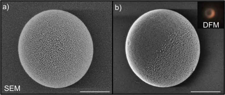
SEM of a 1.3 μm SiO2 Janus particle with a 5 nm Au coating after (a) being pushed upward from the trap into a sticky polymer (gold side always visible) and (b) settling under gravity. Inset is a dark-field image of the sedimented particle. Scale bar = 500 nm.
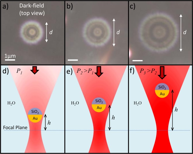
To perform the measurements, the Janus particles were imaged in an upright dark-field microscope (Zeiss Axio Scope A1) with condenser illumination (numerical aperture (NA) = 1.2–1.4) and a water immersion objective (magnification: 100×, NA = 1.0). A small drop of aqueous solution (50–100 μL) containing the Janus particles at low concentration was applied to a microscope coverslip, and the objective was inserted directly into the drop. The optical trap was created with a 1064 nm continuous wave laser, which was expanded and focused through the same objective onto the coverslip. The Janus particles could be trapped stably, however not in the focus of the laser beam. Instead they were displaced axially above the focal point, as can be seen by the defocused rings stemming from the scattering of the Janus particles in dark-field images (Figure 2a). If the laser power is increased, the rings become larger (Figure 2b,c). Thus, the higher the laser power is, the farther the Janus particle is pushed upward with respect to the laser focus (Figure 2d–f). To quantify the axial position of the Janus particles, we performed a control experiment in which a Janus particle was fixed to the substrate, which was moved upward using a 3D nanopositioner stage, effectively shifting and the focal plane was shifted upward. The size of the scattering ring was measured at various heights. As is well known, the size of the ring is linearly dependent on the displacement from the focal plane, and with the ratio we are able to determine the displacement of the Janus particles in the optical trap.21,22
Figure 2.
(a–c) Dark-field images of a Janus particle in an optical trap for increasing laser powers (left to right). (d–f) Schematics of the experimental situations of (a)−(c) with the incident illumination from above. Increasing the laser power causes a reversible axial displacement in a direction opposite the beam propagation.
To qualitatively understand how these particles can be trapped stably far above the optical focus, we consider all of the forces acting on the Janus particle (Figure 3). A scattering force, due to photon pressure, and the gradient force act downward on the Janus particles, guiding them toward the focus of the laser beam. Gravity also acts in this direction, and buoyancy in the reverse direction. A quick estimate of the buoyancy and gravitational force is given using the density of the Janus particle and the water, ρJP and ρw, respectively, the diameter of the particle, DJP, and the gravitational acceleration, g:
Determining the magnitude of the optical forces proves more difficult. Due to the geometric complexity of the system (e.g., roughness of the gold layer), no analytical solution exists. Moreover, this system is also extremely difficult to handle numerically because of the huge size difference between the silica sphere and the gold layer, the aforementioned inhomogeneity of the gold layer, and thus the unknown optical response of the particle. We can however calculate the optical forces for a simple silica sphere of the same dimensions as the precursors used for the Janus particles, based on a formulism derived previously.23,24 This is done for the same parameters used in the experiment: laser wavelength 1064 nm, NA = 1.0, DJP = 1.3 μm, and Plaser = 4–12 mW. This results in values of 26–33 fN at the height of the trapped Janus particle for 4 mW and 65–75 fN for the 12 mW case. These values are lower than what the actual ones will be, due to the scattering and absorption contribution from the gold layer. Nevertheless, these values are roughly an order of magnitude stronger than the buoyancy and gravitational forces, and without an additional force, the Janus particle would move toward the laser focus.
Figure 3.
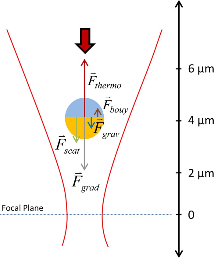
Force diagram of the microelevator system.
The additional force acting on the Janus particle is due to the absorption of light by the gold shell. This leads to a strong heat increase in the gold and the surrounding water, resulting in a thermophoretic force. Accordingly, to counterbalance the other forces, the thermophoretic force must be on the order of several tens of femtonewtons and pointing upward:
To verify this, we needed to determine the orientation of the Janus particle inside the trap. To this end, we added a second coverslip, coated with a polymer (polyDADMAC), to the experiment, sandwiching the Janus particle solution. A drop of water, into which the objective was subsequently inserted, was applied to the second coverslip. We again trapped a Janus particle and then shifted the coverslips upward until the trapped particle stuck to the polymer, becoming attached to the top coverslip. Imaging the substrate surface in an SEM let us determine the orientation of the Janus particle inside the trap (Figure 1a). As can be seen, the gold surface faced away from the surface, which was the case for all Janus particles affixed to the substrate in this manner. The orientation most likely stemmed from the scattering force, which caused the particles to rotate so that the gold surface pointed in the direction of beam propagation. The orientation of the affixed particles on the surface was in clear contrast to Janus particles that sedimented on the bottom coverslip, where the particles were generally lying on their side (Figure 1b). As a consequence, the thermophoretic force acting on the Janus particle in the laser beam points upward, counterbalancing the other forces and enabling the particle to be stably trapped inside the laser beam (Figure 3). To clarify the role of gravity and the character of the thermal force, we considered the same experiment in an inverted microscope setup. In this case, the laser propagation direction is inverted, so the orientation of the particle and all of the forces are in the opposite direction, with the exclusion of gravity (Figure S2). The same microelevator behavior was observed in this configuration, except with a downward axial displacement. This experiment ruled out convection as the mechanism of the axial displacement, because the power-dependent displacement due to convection would be upward in either configuration. The other possibility is self-thermophoresis, resulting in a force on the particle the direction of which is fixed by its orientation. Also it confirmed that gravity does not play a pivotal role as a downward restoring force, as this would lead to a downward ejection in the inverted setup. Consequently, the combined optical forces are the main restoring force keeping the particle from ejection and together with the thermophoretic force the dominant forces in this experiment. The strength of these two main counteracting forces depends differently on the laser power, enabling stable trapping and leading to the upward and downward motion of the Janus particle with increasing and decreasing laser power, respectively.
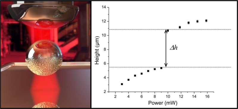
To test the limits of the particle displacement, we increased the trapping laser power, starting at the lowest power (approximately 3 mW) at which trapping was possible. Increasing the laser power led to a displacement of the particle in a nearly linear fashion (Figure 4a). As the actual size of the particles and the thickness of the gold varied, the exact height varied accordingly, yet we obtained an average displacement capability of approximately 330 nm per mW of trapping laser power. Astoundingly, at around 13 mW trapping power the particle jumped inside the trap, moving by roughly 5.3 μm, more than 10 times the amount previously determined. Increasing the power even further led again to a nearly linear displacement of the Janus particle, with roughly the same slope as determined for low trapping powers. Reversing the direction subsequently and reducing the trapping power resulted initially in a linear decrease in particle displacement with the same slope (Figure 4b). The jump happened also in this reverse process and with a similar magnitude of 5.4 μm, albeit at a lower laser power of approximately 11 mW and consequently at a different axial position. Further decreasing the laser power again led to a linear decrease of the displacement with the slope again of the same size as in the forward process. We repeated the measurement for many Janus particles, and each particle displayed a jump of the same distance, albeit at slightly varying laser powers, despite the aforementioned inhomogeneity between the particles. All particles displayed a hysteresis in the jump between upward and downward motion (Figure S3). Due to these observations, we determined that the jump must be related to certain characteristics of the optical trap and thus the laser beam.
Figure 4.
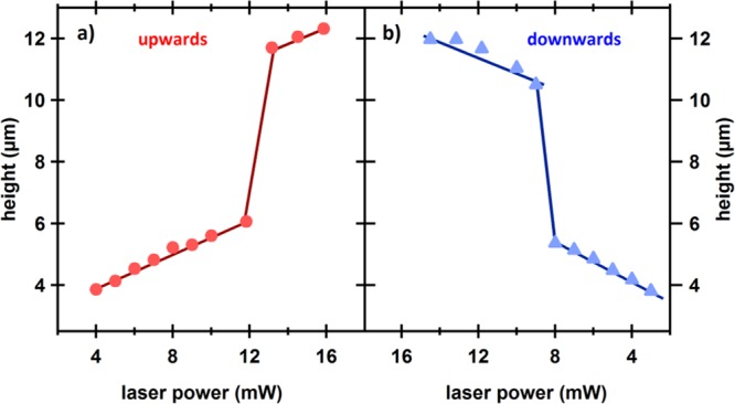
Axial displacement, h, as a function of (a) increasing and (b) decreasing trapping laser power. Increasing the laser power leads to an upward motion of the Janus particle, while a decrease in the laser power leads to a downward motion.
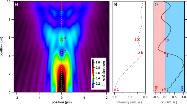
We investigated the jumping of the Janus particle further by modeling the intensity distribution of the laser beam used in this setup. High focusing of a laser beam results in a complex three-dimensional pattern of the light field with multiple local maxima and minima. This has been investigated in detail previously using vector theory.25−28 Here, we used the finite difference time domain (FDTD) method using the FDTD Solutions software. Because of the complexity of the system and the number of unknown parameters of the Janus particles, we looked only at the unperturbed light field and not that which is modified through the presence of a trapped particle. Nevertheless, this simplification illustrates the discontinuity in the Janus particle movement upon changing the laser power. Using a Gaussian beam focused through a thin lens of NA = 1.0 we obtained the spatial beam profile of the laser beam (Figure 5a). A complex pattern of local maxima and minima can be seen above the central focal point. To illustrate the light intensity that is experienced by the particle, we averaged the intensity along the z-direction over the width of the particle (Figure 5b). An oscillation between maxima and minima in the z-direction is apparent; consequently the sign of the intensity gradient, ∇I, oscillates between positive and negative values (Figure 5c). Thus, since the gradient force is proportional to ∇I, as a particle moves along the z-direction, it experiences an alternating pulling and pushing by the gradient force. These results also help to explain the movement of the particle observed when the laser power was increased. An increase in the laser power disproportionately increases the thermophoretic force, driving the particle slowly upward from its original position (point 1 in Figure 5a). Once the intensity gradient is reduced enough, it can no longer compensate for the thermophoretic force, and the particle moves upward quickly, past point 2. At this height the gradient force then becomes repulsive, driving the particle upward even more until a steady point is reached past point 3, where the intensity gradient is once again positive and the gradient force balances out the thermophoretic force. Increasing the laser power further then leads to the upward movement of the particle seen in the experiments. The hysteresis of the particle jump is also explained by the intensity landscape. In both the forward and reverse case the Janus particle resists the change in position because it is attracted to the nearest local intensity maximum. The jump happens when the thermophoretic force becomes either strong enough to overcome the potential barrier of the primary optical trap and push the particle upward to the secondary trap (forward case) or weak enough to allow the particle to settle into a position where it is mainly under the influence of the primary trap (reverse case). Summarily, the Janus particle in a focused Gaussian beam sees an intensity landscape that is more complicated than in a classical optical trap at the laser focus. These intensity peaks form smaller, secondary traps, which have been previously exploited and studied.29,30 Depending on the particle position, it can be attracted to one of multiple intensity peaks (traps). In our experiment, we observed only one jump due to the fact that beyond a certain height the particle became too far out-of-plane to image.
Figure 5.
(a) Axial cross section of the intensity distribution (arbitrary units) of a focused Gaussian beam The red arrow indicates the incident beam direction. (b) The intensity summed over the cross-sectional area of the Janus particle along the z-axis and (c) the gradient of the intensity, ∇I.
In all of the studies presented above the focus of the trapping laser beam was not occupied with the Janus particle located several micrometers above the focus. To explore the potentials of this microelevator, we used it to trap 80 nm Au nanoparticles along with the previously trapped Janus particle (Figure S4). The Au nanoparticle was firmly trapped in all three dimensions and located at the focal point of the laser. No movement of the Au nanoparticle was visible in the microscope. The Janus particle also was trapped at roughly the same height as before, without the Au nanoparticle in the trap. However, while the Au nanoparticle continued to remain stationary, the Janus particle could clearly be seen moving laterally inside the trap. Applying different laser powers led, as before, to the Janus particle moving along the axis of the laser beam. As the height of the Janus particle increased, so also did the lateral motion of the particle. The experiment showed that the Janus particle does not modify the properties of the optical trap strongly, as the Au nanoparticles did not seem to be affected by the Janus particle becoming subsequently trapped. Similarly, the Au particle also did not seem to disturb the trapping potential for the Janus particle, as this appeared to be trapped as stably as for the case without an additional trapped Au nanoparticle. Nevertheless it was possible to control the distance between the Au nanoparticle and the Janus particle inside the trap, to our knowledge one of the first demonstrations of control of the separation between nanoparticles within an optical trap. This can potentially be exploited for several applications, such as remote sensing, force measurements, or controlled heating.
Conclusion
In conclusion, we have demonstrated a controllable photonic microscale elevator composed of a gold/silica Janus particle in an optical-thermal trap. Compared to previous reports of optically induced thermophoretic motion in Janus particles, we have demonstrated unprecedented control over the particle height and orientation in a focused laser beam. The particle height is determined by the equilibrium position at which the scattering, gradient, and thermophoretic force cancel out and can be controlled in a highly reproducible way by adjusting the laser power. We observed a jump in the particle position and a hysteresis effect, both of which are caused by the intensity distribution due to wave interference in the focused beam. The study described here opens the door to new high-precision methods for controlling Janus microswimmers near optical traps. When combined with the variety of potential landscapes that can be produced via spatial light modulators, it will be possible to move many Janus particles in complex, highly controllable configurations. We further extended the possibilities of this technique by simultaneously trapping a second, spherical gold nanoparticle in the trap despite the Janus particle’s presence. We showed that the distance between this and the Janus particle can be controlled precisely, leading to possible applications such as single-molecule detection and force measurements.
Acknowledgments
ERC Advanced Investigator Grant HYMEM, S.C.P. acknowledges support from the Alexander von Humboldt Foundation. We thankfully acknowledge Felix Winterer for the access to his Matlab code based on generalized Mie theory.
Supporting Information Available
This material is available free of charge via the Internet at http://pubs.acs.org.
The authors declare no competing financial interest.
Supplementary Material
References
- Ebbens S. J.; Howse J. R. In Pursuit of Propulsion at the Nanoscale. Soft Matter 2010, 6, 726–738. [Google Scholar]
- Nelson B. J.; Kaliakatsos I. K.; Abbott J. J. Microrobots for Minimally Invasive Medicine. Annu. Rev. Biomed. Eng. 2010, 12, 55–85. [DOI] [PubMed] [Google Scholar]
- Peyer K. E.; Zhang L.; Nelson B. J. Bio-Inspired Magnetic Swimming Microrobots for Biomedical Applications. Nanoscale 2013, 5, 1259–1272. [DOI] [PubMed] [Google Scholar]
- Leoni M.; Kotar J.; Bassetti B.; Cicuta P.; Lagomarsino M. C. A Basic Swimmer at Low Reynolds Number. Soft Matter 2009, 5, 472–476. [Google Scholar]
- Purcell E. M. Life at Low Reynolds-Number. Am. J. Phys. 1977, 45, 3–11. [Google Scholar]
- Snezhko A.; Belkin M.; Aranson I. S.; Kwok W. K. Self-Assembled Magnetic Surface Swimmers. Phys. Rev. Lett. 2009, 102, 118103. [DOI] [PubMed] [Google Scholar]
- Williams B. J.; Anand S. V.; Rajagopalan J.; Saif M. T. A. A Self-Propelled Biohybrid Swimmer at Low Reynolds Number. Nat. Commun. 2014, 5, 3081. [DOI] [PubMed] [Google Scholar]
- Walther A.; Muller A. H. E. Janus Particles: Synthesis, Self-Assembly, Physical Properties, and Applications. Chem. Rev. 2013, 113, 5194–5261. [DOI] [PubMed] [Google Scholar]
- Buttinoni I.; Volpe G.; Kummel F.; Volpe G.; Bechinger C. Active Brownian Motion Tunable by Light. J. Phys.: Condens. Matter. 2012, 24, 284129. [DOI] [PubMed] [Google Scholar]
- Volpe G.; Buttinoni I.; Vogt D.; Kummerer H. J.; Bechinger C. Microswimmers in Patterned Environments. Soft Matter 2011, 7, 8810–8815. [Google Scholar]
- Yang W.; Misko V. R.; Nelissen K.; Kong M.; Peeters F. M. Using Self-Driven Microswimmers for Particle Separation. Soft Matter 2012, 8, 5175–5179. [Google Scholar]
- Bickel T.; Majee A.; Wurger A. Flow Pattern in the Vicinity of Self-Propelling Hot Janus Particles. Phys. Rev. E 2013, 88, 012301. [DOI] [PubMed] [Google Scholar]
- Golestanian R.; Liverpool T. B.; Ajdari A. Designing Phoretic Micro- and Nano-Swimmers. New J. Phys. 2007, 9, 126. [Google Scholar]
- Giddings J. C.; Shinudu P. M.; Semenov S. N. Thermophoresis of Metal Particles in a Liquid. J. Colloid Interface Sci. 1995, 176, 454–458. [Google Scholar]
- Jiang H. R.; Yoshinaga N.; Sano M. Active Motion of a Janus Particle by Self-Thermophoresis in a Defocused Laser Beam. Phys. Rev. Lett. 2010, 105, 268302. [DOI] [PubMed] [Google Scholar]
- Yang M. C.; Ripoll M. Simulations of Thermophoretic Nanoswimmers. Phys. Rev. E 2011, 84, 061401. [DOI] [PubMed] [Google Scholar]
- Baraban L.; Makarov D.; Schmidt O. G.; Cuniberti G.; Leiderer P.; Erbe A. Control over Janus Micromotors by the Strength of a Magnetic Field. Nanoscale 2013, 5, 1332–1336. [DOI] [PubMed] [Google Scholar]
- Baraban L.; Streubel R.; Makarov D.; Han L. Y.; Karnaushenko D.; Schmidt O. G.; Cuniberti G. Fuel-Free Locomotion of Janus Motors: Magnetically Induced Thermophoresis. ACS Nano 2013, 7, 1360–1367. [DOI] [PubMed] [Google Scholar]
- Neuman K. C.; Block S. M. Optical Trapping. Rev. Sci. Instrum. 2004, 75, 2787–2809. [DOI] [PMC free article] [PubMed] [Google Scholar]
- Merkt F. S.; Erbe A.; Leiderer P. Capped Colloids as Light-Mills in Optical Traps. New J. Phys. 2006, 8, 216. [Google Scholar]
- Lee S.-H.; Roichman Y.; Yi G.-R.; Kim S.-H.; Yang S.-M.; van Blaaderen A.; van Oostrum P.; Grier D. G. Characterizing and Tracking Single Colloidal Particles with Video Holographic Microscopy. Opt. Express 2007, 15, 18275–18282. [DOI] [PubMed] [Google Scholar]
- Speidel M.; Jonáš A.; Florin E.-L. Three-Dimensional Tracking of Fluorescent Nanoparticles with Subnanometer Precision by Use of Off-Focus Imaging. Opt. Lett. 2003, 28, 69–71. [DOI] [PubMed] [Google Scholar]
- Nieminen T. A.; Loke V. L. Y.; Stilgoe A. B.; Knoner G.; Branczyk A. M.; Heckenberg N. R.; Rubinsztein-Dunlop H. Optical Tweezers Computational Toolbox. J. Opt. A: Pure Appl. Opt. 2007, 9, S196–S203. [Google Scholar]
- Nieminen T. A.; du Preez-Wilkinson N.; Stilgoe A. B.; Loke V. L. Y.; Bui A. A. M.; Rubinsztein-Dunlop H. Optical Tweezers: Theory and Modelling. J. Quant. Spectrosc. Radiat. Transfer 2014, 146, 59–80. [Google Scholar]
- Li Y.; Wolf E. Three-Dimensional Intensity Distribution near the Focus in Systems Different Fresnel Numbers. J. Opt. Soc. Am. A 1984, 1, 801–808. [Google Scholar]
- Li Y.; Yu F. T. S. Intensity Distribution near the Focus of an Apertured Focused Gaussian Beam. Opt. Commun. 1989, 70, 1–7. [Google Scholar]
- Nasse M. J.; Woehl J. C. Realistic Modeling of the Illumination Point Spread Function in Confocal Scanning Optical Microscopy. J. Opt. Soc. Am. A 2010, 27, 295–302. [DOI] [PubMed] [Google Scholar]
- Egner A.; Hell S. W.. Aberrations in Confocal and Multi-Photon Fluorescence Microscopy Induced by Refractive Index Mismatch; Springer: US, 2006. [Google Scholar]
- Kyrsting A.; Bendix P. M.; Oddershede L. B. Mapping 3D Focal Intensity Exposes the Stable Trapping Positions of Single Nanoparticles. Nano Lett. 2013, 13, 31–35. [DOI] [PubMed] [Google Scholar]
- Brzobohatý O.; Šiler M.; Ježek J.; Jákl P.; Zemánek P. Optical Manipulation of Aerosol Droplets Using a Holographic Dual and Single Beam Trap. Opt. Lett. 2013, 38, 4601–4604. [DOI] [PubMed] [Google Scholar]
Associated Data
This section collects any data citations, data availability statements, or supplementary materials included in this article.


